Troubleshooting And Repair Of Television Sets
Notes On The Troubleshooting And Repair Of Television Sets
Contents:
a.. Chapter 1)
b.. Chapter 2) Introduction
c.. 2.1) Television at the crossroads
d.. 2.2) Television receiver fundamentals
e.. 2.3) TV repair
f.. 2.4) Repair or replace
g.. Chapter 3) TV Receivers 101
h.. 3.1) Subsystems of a television set
i.. 3.2) Why projection TVs are not just normal TVs in big boxes
j.. 3.3) For more information on TV technology
k.. 3.4) On-line tech-tips databases
l.. Chapter 4) CRT Basics
m.. 4.1) Color CRTs - shadow masks and aperture grills
n.. 4.2) Degaussing (demagnetizing) a CRT
o.. Chapter 5) TV Placement And Preventive Maintenance
p.. 5.1) General TV placement considerations
q.. 5.2) Preventive maintenance
r.. 5.3) Warning about using a TV as a computer or video game display
s.. Chapter 6) TV Troubleshooting
t.. 6.1) SAFETY
u.. 6.2) Safety guidelines
v.. 6.3) Troubleshooting tips
w.. 6.4) Test equipment
x.. 6.5) Incredibly Handy widgets
y.. 6.6) Safe discharging of capacitors in TVs and video monitors
z.. 6.7) Additional information on discharging CRTs
aa.. 6.8) Safe troubleshooting techniques for line powered TVs
ab.. 6.9) The series light bulb trick
ac.. 6.10) Getting inside a TV
ad.. 6.11) Specific considerations before poking around inside a TV
ae.. 6.12) Specific considerations before poking around inside a TV or monitor
af.. 6.13) Dusting out the inside of a TV
ag.. 6.14) Troubleshooting a TV with the mainboard disconnected
ah.. Chapter 7) TV Adjustment
ai.. 7.1) User picture adjustment
aj.. 7.2) Internal adjustments
ak.. 7.3) Focus adjustment
al.. 7.4) Adjustment of the internal SCREEN and color controls
am.. 7.5) Optimal procedure for setting brightness/background and screen adjustments
an.. 7.6) Color balance adjustment
ao.. 7.7) Horizontal position, size, and linearity adjustment
ap.. 7.8) Vertical position, size, and linearity adjustment
aq.. 7.9) Pincushion adjustments
ar.. 7.10) Geometry adjustment
as.. 7.11) Why is the convergence on my set bad near the edges
at.. 7.12) CRT purity and convergence problems
au.. 7.13) CRT purity adjustment
av.. 7.14) CRT convergence adjustment
aw.. 7.15) Tilted picture
ax.. 7.16) B/W TV size, position, and geometry adjustments
ay.. Chapter 8) Low Voltage Power Supply Problems
az.. 8.1) Low voltage power supply fundamentals
ba.. 8.2) Typical TV power supply front end
bb.. 8.3) Totally dead set
bc.. 8.4) Intermittently dead set - bad cordset
bd.. 8.5) Power button on set is flakey
be.. 8.6) TV blows fuse
bf.. 8.7) Fuse blows or TV blows up when sync is disrupted
bg.. 8.8) Internal fuse blew during lightning storm (or elephant hit power pole)
bh.. 8.9) Fuse replaced but TV clicks with power-on but no other action
bi.. 8.10) Power-on tick-tick-tick or click-click-click but no other action
bj.. 8.11) No picture or raster and no sound
bk.. 8.12) Reduced width picture and/or hum bars in picture and/or hum in sound
bl.. 8.13) Excessive B+ from fixed regulator like STR30123/STR30130/STR30135
bm.. 8.14) TV power cycling on and off
bn.. 8.15) Dead TV with periodic tweet-tweet, flub-flub, or low-low voltage
bo.. 8.16) Shorted Components
bp.. 8.17) Startup problems - nothing happens, click, or tick-tick-tick sound
bq.. 8.18) TV turns off after warming up
br.. 8.19) TV doesn't power up immediately
bs.. 8.20) Old TV requires warmup period
bt.. 8.21) TV shuts down with bright picture or when brightness is turned up
bu.. 8.22) Relays in the Power Circuitry of TVs
bv.. 8.23) Flameproof Resistors
bw.. 8.24) Width and height change with warmup
bx.. 8.25) Problems with SCR based regulators
by.. 8.26) TV shuts down with dark picture or when changing channels
bz.. Chapter 9) Deflection Problems
ca.. 9.1) Deflection fundamentals
cb.. 9.2) About the vertical scan rate
cc.. 9.3) Picture squeezed in then died
cd.. 9.4) Horizontal deflection shutting down
ce.. 9.5) Horizontal lock lost
cf.. 9.6) Insufficient width (without hum bars)
cg.. 9.7) Vertical lock lost
ch.. 9.8) Vertical squashed
ci.. 9.9) Part of picture cut off
cj.. 9.10) Single Vertical Line
ck.. 9.11) Single Horizontal Line
cl.. 9.12) Keystone shaped picture
cm.. 9.13) Loss of Horizontal Sync (also applies to vertical) after Warmup
cn.. 9.14) Intermittent jumping or jittering of picture or other random behavior
co.. 9.15) Horizontal output transistors keep blowing (or excessively hot)
cp.. 9.16) Horizontal output transistors blowing at random intervals
cq.. 9.17) Vertical foldover
cr.. 9.18) Comments on vertical problems
cs.. 9.19) Excessive width/pincushioning problems
ct.. 9.20) Deflection yoke testing
cu.. 9.21) Deflection yoke repair
cv.. 9.22) Testing of flyback (LOPT) transformers
cw.. Chapter 10) High Voltage Power Supply Problems
cx.. 10.1) HV power supply fundamentals
cy.. 10.2) What is a tripler?
cz.. 10.3) High voltage shutdown due to X-ray protection circuits
da.. 10.4) Low or no high voltage
db.. 10.5) Excessive high voltage
dc.. 10.6) Snaps, crackles, and other HV breakdown
dd.. 10.7) Arcing, sparking, or corona from CRT HV anode (red wire/suction cup)
de.. 10.8) Arcing from flyback or vicinity
df.. 10.9) Dave's complete procedure for repair of an arcing flyback
dg.. 10.10) Arcing at spark gaps and gas discharge tubes on CRT neck board or elsewhere
dh.. 10.11) Arcing due to bad connections to or disconnected CRT return
di.. 10.12) Flashovers inside the CRT
dj.. 10.13) Ozone smell and/or smoke from TV
dk.. 10.14) X-ray and other EM emission from my monitor?
dl.. 10.15) Should I be worried about X-ray exposure while servicing a TV or monitor?
dm.. 10.16) Flyback shot by 4 year old with water pistol
dn.. 10.17) Blooming or breathing problems
do.. 10.18) Erratic focus or screen (G2) voltage and/or controls on flyback
dp.. 10.19) Focus/Screen divider bypass surgery
dq.. 10.20) Decaying or erratic focus or screen (G2) voltages
dr.. 10.21) Disconnecting focus wire from CRT driver board
ds.. 10.22) Focus or screen voltage drifts after warmup only when CRT is connected
dt.. Chapter 11) Raster, Color, and Video Problems
du.. 11.1) No color - black and white picture
dv.. 11.2) Saturated color but almost no brightness
dw.. 11.3) Brightness control has no effect
dx.. 11.4) One color is too weak or too strong
dy.. 11.5) Psychodelic color
dz.. 11.6) No picture/dark picture/erratic picture
ea.. 11.7) TV and Monitor Manufacturing Quality and Cold Solder Joints
eb.. 11.8) Why can't TV manufacturers learn to solder properly?
ec.. 11.9) Intermittent or missing colors
ed.. 11.10) Some commentary on monitor and TV whacking
ee.. 11.11) Retrace lines in picture
ef.. 11.12) White/gray retrace lines
eg.. 11.13) Red, green, or blue retrace lines
eh.. 11.14) Bad CRT causing retrace lines
ei.. 11.15) Red, green, or blue full on - fog over picture
ej.. 11.16) Shorts in a CRT
ek.. 11.17) Providing isolation for a CRT H-K short
el.. 11.18) Rescuing a shorted CRT
em.. 11.19) Picture tube replacement
en.. 11.20) Dark picture
eo.. 11.21) Brightening an old CRT
ep.. 11.22) Picture tube brightener
eq.. 11.23) More drastic measures to brighten CRT
er.. 11.24) Left portion of screen is dark or faded
es.. 11.25) Color balance changes across screen from left to right
et.. 11.26) Bleeding highlights
eu.. 11.27) Trailing lines in one or more colors
ev.. 11.28) Brightness changes from left-to-right across screen
ew.. 11.29) Picture fades in and out
ex.. 11.30) Occasional brightness flashes
ey.. 11.31) Excessive brightness and/or washed out picture
ez.. 11.32) Bad focus (fuzzy picture)
fa.. 11.33) Focus drift with warmup
fb.. 11.34) Bad focus and adjustment changes brightness
fc.. 11.35) Charlie's comments on focus problems
fd.. 11.36) Blank picture, good channel tuning and sound
fe.. 11.37) Purple blob - or worse
ff.. 11.38) Color rings - bullseye pattern
fg.. 11.39) Magnet fix for purity problems - if duct tape works, use it!
fh.. 11.40) Color TV only displays one color
fi.. 11.41) Disappearing Red (or other color)
fj.. 11.42) The wandering black blob on old Sony
fk.. 11.43) Vertical brightness or color bars
fl.. Chapter 12) Tuner, AGC, and Sync Problems
fm.. 12.1) No reception from antenna or cable
fn.. 12.2) Picture is overloaded, washed out, or noisy
fo.. 12.3) Jumping picture on white scenes
fp.. 12.4) Interference when using VCR RF connection
fq.. 12.5) RF Interference on TV
fr.. 12.6) Problems with ground loops and video hum bars
fs.. 12.7) Missing or noisy channel or block of channels
ft.. 12.8) Loss of Channel after Warmup
fu.. 12.9) Channel tuning drifts as set warms up
fv.. 12.10) Noise in picture and sound due to bright scene
fw.. 12.11) Internal interference - switchmode power supplies and digital circuitry
fx.. 12.12) Those darn rabbit ears
fy.. 12.13) Herringbone lines in picture
fz.. Chapter 13) Audio Problems
ga.. 13.1) Picture fine, no audio
gb.. 13.2) Weak or distorted audio
gc.. 13.3) Buzzing TV
gd.. 13.4) High pitched whine or squeal from TV with no other symptoms
ge.. 13.5) Reducing/eliminating yoke noise
gf.. 13.6) Whining when off?
gg.. Chapter 14) Miscellaneous Problems
gh.. 14.1) General erratic behavior
gi.. 14.2) Wiring transmitted interference
gj.. 14.3) Jittering or flickering due to problems with AC power
gk.. 14.4) TV blows fuses or trips breakers or worse when A/V connections are made
gl.. 14.5) My TV has the shakes
gm.. 14.6) TV displays black box with normal picture border
gn.. 14.7) Advertising overload
go.. 14.8) Strange codes appearing on TV screen
gp.. 14.9) Releasing 'demo' mode
gq.. 14.10) TV was rained on
gr.. 14.11) TV was dropped
gs.. 14.12) Really cleaning a TV inside and out
gt.. 14.13) Setup menus will not go away or hieroglyphics on screen
gu.. 14.14) Setup adjustments lost - TV service codes
gv.. 14.15) Service menu caution
gw.. 14.16) Strange number in upper left corner in Magnavox service mode
gx.. 14.17) TV doesn't work after being in storage
gy.. 14.18) Older TVs with multiple intermittent problems
gz.. 14.19) TV has burning smell
ha.. 14.20) Static discharge noise and picture tube quality
hb.. 14.21) Revival of dead or tired remote control units
hc.. 14.22) Problems with the IR remote receiver
hd.. 14.23) So you lost your original remote (or it fell in the toilet)
he.. 14.24) Loudspeakers and TVs
hf.. 14.25) Should I replace all the electrolytic capacitors if I find a bad one?
hg.. 14.26) Sweet little old ladies and TVs from attic
hh.. 14.27) Phantom spot or blob on CRT after set is shut off
hi.. 14.28) Disposing of dead TVs (CRTs and charged HV capacitors)
hj.. 14.29) Shock and/or spark when connecting cable or other A/V components
hk.. 14.30) What is the deal with Macrovision copy protection?
hl.. 14.31) AGC and copy protection
hm.. 14.32) On-screen clock runs slow or fast
hn.. 14.33) Cold problems with cold TVs - or - an unhappy Christmas
ho.. Chapter 15) Some Model Specific Problems
hp.. 15.1) Erratic problems with older GE TVs
hq.. 15.2) Erratic problems on late model GE, RCA, or ProScan TV
hr.. 15.3) Sylvania/Magnavox/Philips - no startup
hs.. 15.4) Sony TVs/monitors and Hstat
ht.. 15.5) More on Hstat
hu.. Chapter 16) Items of Interest
hv.. 16.1) An informal history of X-ray protection
hw.. 16.2) What is this goop around some electrolytic capacitors and other components?
hx.. 16.3) What does the flyback (LOPT) transformer do?
hy.. 16.4) Why do flyback (LOPT) transformers fail?
hz.. 16.5) Brief comments on testing the HOT
ia.. 16.6) CRT rejuvenation
ib.. 16.7) Memory chips in TVs
ic.. 16.8) How does Picture-In-Picture (PIP) work?
id.. 16.9) Tony's notes on setting convergence on delta gun CRTs
ie.. 16.10) Saga and general setup for large CRT TVs
if.. 16.11) Liquid coupling fluid for projection TVs
ig.. 16.12) Comments on color purity, set orientation, and doming
ih.. 16.13) About instant-on TVs
ii.. 16.14) About gadgets to use house wiring as TV antenna
ij.. 16.15) Can I add an S-Video input to my TV or VCR?
ik.. 16.16) How do I add A/V inputs or outputs to a TV which does not have them built in?
il.. 16.17) Adding variable volume headphones to a TV
im.. 16.18) Building a Frankenstein TV
in.. 16.19) Turning a TV (or monitor) into an oscilloscope?
io.. 16.20) Displaying a video signal as a picture on an oscilloscope
ip.. 16.21) Use of surge suppressors and line filters
iq.. 16.22) GFCI tripping with TV, monitor, or other high tech equipment
ir.. 16.23) Multisystem TVs
is.. 16.24) Playing NTSC videotape on a PAL TV
it.. 16.25) Buying a TV in Europe
iu.. 16.26) Could a TV be modified for 3D (stereo) display?
iv.. 16.27) Displaying TV on a computer monitor
iw.. 16.28) Displaying computer video on a TV
ix.. 16.29) How can I couple 4 TV screens to make them act like only one?
iy.. 16.30) What is Scan Velocity Modulation?
iz.. 16.31) What is Kell factor with respect to interlaced displays?
ja.. 16.32) Homemade V-chip (or at least viewing limiter)
jb.. 16.33) What is Aquadag?
jc.. 16.34) Combined computer monitor and TV
jd.. 16.35) Interesting TV Switch Mode Power Supply
je.. 16.36) The horizontal output transistor substitution jig trick
jf.. 16.37) Ken's comments on (TV) SMPS repair
jg.. 16.38) IR detector circuit
jh.. 16.39) UK Satellite TV information
ji.. Chapter 17) International Color Television Standards
jj.. 17.1) Brief description of international color TV standards
jk.. 17.2) Some questions and answers about TV standards
jl.. 17.3) Politically Correct TV Standards
jm.. 17.4) Variations on a 'standard' - the PAL system
jn.. 17.5) What about PAL sets WITH a tint/hue control?
jo.. 17.6) TV, shortwave, power worldwide
jp.. 17.7) Color television standards worldwide
jq.. 17.8) Cable channel allocation
jr.. 17.9) Notes on cable and broadcast frequencies
js.. 17.10) How did the (vertical) frame rate get chosen
jt.. 17.11) Why is the NTSC color subcarrier such a weird frequency?
ju.. 17.12) What is the maximal allowed deviation of the horizontal frequency?
jv.. 17.13) Informal comparison of TV standards
jw.. 17.14) PAL-plus
jx.. Chapter 18) Service Information
jy.. 18.1) Advanced TV troubleshooting
jz.. 18.2) Service manuals for really old TVs
ka.. 18.3) How to locate service info when all the little stickers have fallen off
kb.. 18.4) Techical assistance help numbers
kc.. 18.5) Web resources
kd.. 18.6) Parts information
ke.. 18.7) Suggested references
kf.. 18.8) FCC ID Numbers of TVs
kg.. 18.9) Interchangeability of components
kh.. 18.10) Horizontal output transistor pinouts
ki.. 18.11) How do you locate the HOT
kj.. 18.12) Replacement power transistors while testing
kk.. 18.13) Testing of replacement HOTs
kl.. 18.14) Removing and replacing the deflection yoke
km.. 18.15) Swapping of deflection yokes
kn.. 18.16) Swapping of CRTs
ko.. 18.17) Decayed glue in electronic equipment
kp.. 18.18) Repair parts sources
--------------------------------------------------------------------------------
2.1) Television at the crossroads
Television in substantially its present form has been with us for nearly
50 years. It is a tribute to the National Television Standards Committee
(NTSC) that the color television standards agreed upon in the early 1950s
have performed remarkably well making quite efficient use of valuable radio
spectrum space and the psychovisual characteristics of the human eye-brain
system. However, HDTV (High Definition TV) will supplant and ultimately
replace the current standards. We will all come to expect its superior
resolution, freedom from noise and ghosting, and pure CD sound. Yet, the
perceived quality of TV broadcasts and cable will never likely be the major
issue with most consumers. Content will continue to be the biggest problem.
It is likely that in roughly 15 years, HDTV - digitally processed and
transmitted as 1s and 0s - will completely replace the current system.
Acceptance in the marketplace is by no means assured but with the merging
of TV and computers - with the Internet as a driving force - it would seem
that the days of the stand-alone analog TV set are numbered.
--------------------------------------------------------------------------------
2.2) Television receiver fundamentals
The basic color television receiver must perform the same functions today as
40 years ago. (Since B/W is a subset of the color standard, most references
in this document will be for color except as noted). A studio video monitor
includes all of the functions of a television receiver except the tuner
and IF (which rarely fail except for bad connections or perhaps lightning
strikes to the antenna or cable connection). Therefore most
of the repair information in this document is applicable to both TVs and
studio monitors. Modern computer monitors share many similarities with
TVs but the multisync and high scan rate deflection circuitry and more
sophisticated power supplies complicates their servicing.
As of this writing, all but the smallest TVs are based on the Cathode
Ray Tube (CRT) as the display device. Tiny pocket sets, camcorder
viewfinders, and the like have started using LCD (Liquid Crystal Display)
panels but these are still inferior to the CRT for real time video.
There has always been talk of 'the picture on the wall' display. While
we are closer than ever to this possibility, I believe that mass production
of an affordable wall mural TV screen is still decades away. The reason
is simple economics - it is really hard to beat the simplicity of the
shadow mask CRT. For example, a decent quality active matrix color LCD
panel may add $1000 to the cost of a notebook computer compared to $200
for a VGA monitor. More of these panels go in the dumpster than make it
to product do to manufacturing imperfections.
Projection - large screen - TVs may, on the other hand, be able to take
advantage of a novel development in integrated micromachining - the
Texas Instruments Inc. Digital Micromirror Device (DMD). This is basically
an integrated circuit with a tiltable micromirror for each pixel fabricated
on top of a static memory - RAM - cell. This technology would
permit nearly any size projection display to be produced and would
therefore be applicable to HDTV. Since it is a reflective device, the
light source can be as bright as needed. However, this is still not
a commercial product but stay tuned.
--------------------------------------------------------------------------------
2.3) TV repair
Unlike VCRs or CD players where any disasters are likely to only affect
your pocketbook, TVs can be dangerous. Read, understand, and follow the
set of safety guidelines provided later in this section whenever working
on TVs, monitors, or other similar high voltage equipment.
If you do go inside, beware: line voltage (on large caps) and high voltage
(on CRT) for long after the plug is pulled. There is the added danger of
CRT implosion for carelessly dropped tools and often sharp sheetmetal
shields which can injure if you should have a reflex reaction upon touching
something you should not touch. In inside of a TV or monitor is no place
for the careless or naive.
Having said that, a basic knowledge of how a TV set works and what can
go wrong can be of great value even if you do not attempt the repair yourself.
It will enable you to intelligently deal with the service technician. You
will be more likely to be able to recognize if you are being taken for a ride
by a dishonest or just plain incompetent repair center. For example, a
faulty picture tube CANNOT be the cause of a color television only displaying
shows in black-and-white. The majority of consumers probably do not know even
this simple fact. Such a problem is usually due to a bad capacitor or other
10 cent part.
This document will provide you with the knowledge to deal with a large
percentage of the problems you are likely to encounter with your TVs.
It will enable you to diagnose problems and in many cases, correct them
as well. With minor exceptions, specific manufacturers and models
will not be covered as there are so many variations that such a treatment would
require a huge and very detailed text. Rather, the most common problems
will be addressed and enough basic principles of operation will be provided
to enable you to narrow the problem down and likely determine a course of
action for repair. In many cases, you will be able to do what is required
for a fraction of the cost that would be charged by a repair center.
Should you still not be able to find a solution, you will have learned a great
deal and be able to ask appropriate questions and supply relevant information
if you decide to post to sci.electronics.repair. It will also be easier to do
further research using a repair text such as the ones listed at the end of
this document. In any case, you will have the satisfaction of knowing you
did as much as you could before taking it in for professional repair.
With your new-found knowledge, you will have the upper hand and will not
easily be snowed by a dishonest or incompetent technician.
--------------------------------------------------------------------------------
2.4) Repair or replace
If you need to send or take the TV to a service center, the repair
could easily exceed half the cost of a new TV. Service centers
may charge up to $50 or more for providing an initial estimate of repair
costs but this will usually be credited toward the total cost of the repair
(of course, they may just jack this up to compensate for their bench time).
TV prices have been dropping almost as fast as PC prices. Therefore, paying
such prices for repair just may not make sense. Except for picture tube
problems, most TV faults can be corrected without expensive parts, however.
Keeping a 5 year old TV alive may be well worthwhile as basic TV performance
and important features have not changed in a long time.
If you can do the repairs yourself, the equation changes dramatically as
your parts costs will be 1/2 to 1/4 of what a professional will charge
and of course your time is free. The educational aspects may also be
appealing. You will learn a lot in the process. Thus, it may make sense
to repair that old clunker for your game room or beach house. (I would
suggest the kid's room but most TV watching just rots the brain anyhow so
a broken TV may be more worthwhile educationally than one that works.)
--------------------------------------------------------------------------------
Chapter 3) TV Receivers 101
--------------------------------------------------------------------------------
3.1) Subsystems of a television set
A TV set includes the following functional blocks:
1. Low voltage power supply (some may also be part of (2)). Most of the lower
voltages used in the TV may be derived from the horizontal deflection
circuits. Sometimes, there is a separate switching power supply but
this would be the exception. Rectifier/filter capacitor/regulator from AC
line provides the B+ to the switching power supply or horizontal
deflection system. Degauss operates off of the line whenever power is
turned on (after having been off for a few minutes) to demagnetize the CRT.
2. Horizontal deflection. These circuits provide the waveforms needed to
sweep the electron beam in the CRT across and back some 15,734 times
per second (for NTSC). The horizontal sync pulse from the sync separator
locks the horizontal deflection to the video signal.
3. Vertical deflection. These circuits provide the waveforms needed to
sweep the electron beam in the CRT from top to bottom and back 60 times
per second (for NTSC). The vertical sync pulse from the sync separator
locks the vertical deflection to the video signal.
4. CRT high voltage (also part of (2)). A modern color CRT requires
up to 30 KV for a crisp bright picture. Rather than having a totally
separate power supply, nearly every TV on the planet derives the HV
(as well as many other voltages) from the horizontal deflection using
a special transformer called a 'flyback' or 'Line OutPut Transformer (LOPT)
for those of you on the other side of the lake.
5. Tuner, IF, AGC, video and audio demodulators. Input is the antenna or
cable signal and output are baseband video and audio signals. There is
usually someplace inside the TV where line level video and audio are
present but it may not be accessible from the outside of the cabinet
unless you paid for the more expensive model with the A/V option.
Very often, the tuner is a shielded metal box positioned on the bottom
right (as viewed from the front) separate from the main circuit board.
Sometimes it is on the main circuit board. The IF section may be in
either place.
On older or cheap TVs with a knob tuner, this is usually mounted to the
front panel by itself. There are usually separate boxes for the VHF and
UHF tuners.
6. Chroma demodulator. Input is the baseband video signal. Outputs are
the individual signals for the red, green, and blue video to the CRT.
7. Video drivers (RGB). These are almost always located on a little
circuit board plugged directly onto the neck of the CRT. They boost
the output of the chroma demodulator to the hundred volts or so needed
to drive the cathodes of the CRT.
8. Sync separator. Input is baseband video. Output is horizontal and
vertical sync pulses to control the deflection circuits.
9. Audio amplifier/output. The line level audio is amplified to drive
a set of speakers. If this is a stereo TV, then these circuits must
also perform the stereo demultiplexing.
10. System control. Most modern TVs actually use a microcontroller - a fixed
program microcomputer to perform all user interface and control functions
from the front panel and remote control. These are becoming increasingly
sophisticated. However, they do not fail often. Older TVs use a bunch
of knobs and switches and these are prone to wear and dirt.
Most problems occur in the horizontal deflection and power supply sections.
These run at relatively high power levels and some components run hot.
The high voltage section is prone to breakdown and arcing as a result
of hairline cracks, humidity, dirt, etc.
The tuner components are usually quite reliable unless the antenna experiences
a lightning strike. However, it seems that even after 20+ years of
solid state TVs, manufacturers still cannot reliably solder the tuner
connectors and shields so that bad solder connections in these areas are
common even in new sets.
--------------------------------------------------------------------------------
3.2) Why projection TVs are not just normal TVs in big boxes
In order to achieve the necessary brightness with a large display format,
three separate monochrome CRTs are used with optics to combine the three images
properly at the screen. This creates an entire set of additional problems in
design.
(From: Jeroen H. Stessen (Jeroen.Stessen@ehv.ce.philips.com)).
The average projection TV has about twice as many parts as its direct-view
counterpart. Some of the extra parts are essential for projection because CRT
projection tubes require dynamic convergence. The other extra parts have to do
with the fact that a more expensive TV also should have some extra features,
like Dolby ProLogic sound, a satellite tuner and such.
Generally, the electronics are based on a standard chassis that is also used
for direct-view CRT television. Even the deflection circuits require minor
adaptations at most. The high-voltage circuit is different because the EHT,
focus and G2 voltages must be distributed over 3 CRTs. So this requires a
special high-voltage part, which also includes an EHT capacitor and bleeder.
There will be 3 CRT panels with video amplifiers. Because of the extremely
high brightness, projection tubes will burn the phosphor screen immediately in
fault conditions so a protection circuit is essential.
And last but certainly not least, there is the dynamic convergence panel. The
heart is a waveform generator IC, often of a Japanese brand but nowadays
there's also a digital variant by Philips. The old-fashioned way requires many
many potentiometers to program the waveforms. Then there's 5 or 6 convergence
amplifiers and a corresponding extra power supply. And usually this is where
the single deflection circuits are distributed to the 3 CRTs. At the same
time the deflection currents are sensed for the protection circuits.
Designing a PTV from a DVTV requires several man-years of work. In the
factory, a special corner is devoted to the assembly. There you'll find
specially educated people and the speed of the assembly line is a lot lower
than usual. It requires many more adjustments, e.g. 3 optical and 3 electrical
focus adjustments and then convergence.
--------------------------------------------------------------------------------
3.3) For more information on TV technology
The books listed in the section: "Suggested references" include additional
information on the theory and implementation of the technology of television
standards and TV receivers.
--------------------------------------------------------------------------------
3.4) On-line tech-tips databases
A number of organizations have compiled databases covering thousands of common
problems with VCRs, TVs, computer monitors, and other electronics equipment.
Most charge for their information but a few, accessible via the Internet, are
either free or have a very minimal monthly or per-case fee. In other cases, a
limited but still useful subset of the for-fee database is freely available.
A tech-tips database is a collection of problems and solutions accumulated by
the organization providing the information or other sources based on actual
repair experiences and case histories. Since the identical failures often
occur at some point in a large percentage of a given model or product line,
checking out a tech-tips database may quickly identify your problem and
solution.
In that case, you can greatly simplify your troubleshooting or at least
confirm a diagnosis before ordering parts. My only reservation with respect
to tech-tips databases in general - this has nothing to do with any one in
particular - is that symptoms can sometimes be deceiving and a solution that
works in one instance may not apply to your specific problem. Therefore,
an understanding of the hows and whys of the equipment along with some good
old fashioned testing is highly desirable to minimize the risk of replacing
parts that turn out not to be bad.
The other disadvantage - at least from one point of view - is that you do not
learn much by just following a procedure developed by others. There is no
explanation of how the original diagnosis was determined or what may have
caused the failure in the first place. Nor is there likely to be any list
of other components that may have been affected by overstress and may fail
in the future. Replacing Q701 and C725 may get your equipment going again
but this will not help you to repair a different model in the future.
Having said that, here are three tech-tips sites for computer monitors, TVs,
and VCRs:
* http://www.anatekcorp.com/techforum.htm (currently free).
* http://www.repairworld.com/ ($8/month).
* http://elmswood.guernsey.net/ (Free, very limited).
* http://ramiga.rnet.cgl.com/electronics/info.html (free large text files).
This one has quite a bit of info for just TVs (at present):
* http://home.inreach.com/ba501/Tech_Tip_Page.htm
These types of sites seem to come and go so it is worth checking them out from
time-to-time even if you don't have a pressing need. If possible, download
and archive any useful information for use on a rainy day in the future.
--------------------------------------------------------------------------------
Chapter 4) CRT Basics
Note: Most of the information on TV and monitor CRT construction, operation,
interference and other problems. has been moved to the document: "TV and Monitor CRT (Picture Tube) Information". The following is just a brief
introduction with instructions on degaussing.
--------------------------------------------------------------------------------
4.1) Color CRTs - shadow masks and aperture grills
All color CRTs utilize a shadow mask or aperture grill a fraction of an
inch (1/2" typical) behind the phosphor screen to direct the electron beams
for the red, green, and blue video signals to the proper phosphor dots.
Since the electron beams for the R, G, and B phosphors originate from
slightly different positions (individual electron guns for each)
and thus arrive at slightly different angles, only the proper phosphors
are excited when the purity is properly adjusted and the necessary
magnetic field free region is maintained inside the CRT. Note that
purity determines that the correct video signal excites the
proper color while convergence determines the geometric
alignment of the 3 colors. Both are affected by magnetic fields.
Bad purity results in mottled or incorrect colors. Bad convergence
results in color fringing at edges of characters or graphics.
The shadow mask consists of a thin steel or InVar (a ferrous alloy)
with a fine array of holes - one for each trio of phosphor
dots - positioned about 1/2 inch behind the surface of the phosphor
screen. With most CRTs, the phosphors are arranged in triangular
formations called triads with each of the color dots at the apex
of the triangle. With many TVs and some monitors, they are
arranged as vertical slots with the phosphors for the 3 colors
next to one another.
An aperture grille, used exclusively in Sony Trinitrons (and now
their clones as well), replaces the shadow mask with an array of finely
tensioned vertical wires. Along with other characteristics of the
aperture grille approach, this permits a somewhat higher possible
brightness to be achieved and is more immune to other problems like
line induced moire and purity changes due to local heating causing
distortion of the shadow mask.
However, there are some disadvantages of the aperture grille design:
* weight - a heavy support structure must be provided for the tensioned
wires (like a piano frame).
* price (proportional to weight).
* always a cylindrical screen (this may be considered an advantage
depending on your preference.
* visible stabilizing wires which may be objectionable or unacceptable
for certain applications.
Apparently, there is no known way around the need to keep the fine
wires from vibrating or changing position due to mechanical shock
in high resolution tubes and thus all Trinitron monitors require
1, 2, or 3 stabilizing wires (depending on tube size) across the
screen which can be see as very fine lines on bright images. Some
people find these wires to be objectionable and for some critical
applications, they may be unacceptable (e.g., medical diagnosis).
--------------------------------------------------------------------------------
4.2) Degaussing (demagnetizing) a CRT
Degaussing may be required if there are color purity problems with the
display. On rare occasions, there may be geometric distortion caused
by magnetic fields as well without color problems. The CRT can get
magnetized:
* if the TV or monitor is moved or even just rotated.
* if there has been a lightning strike nearby. A friend of mine
had a lightning strike near his house which produced all of the
effects of the EMP from a nuclear bomb.
* If a permanent magnet was brought near the screen (e.g., kid's
magnet or megawatt stereo speakers).
* If some piece of electrical or electronic equipment with unshielded
magnetic fields is in the vicinity of the TV or monitor.
Degaussing should be the first thing attempted whenever color
purity problems are detected. As noted below, first try the
internal degauss circuits of the TV or monitor by power cycling a few
times (on for a minute, off for 30 minutes, on for a minute, etc.)
If this does not help or does not completely cure the problem,
then you can try manually degaussing.
Commercial CRT Degaussers are available from parts distributors
like MCM Electronics and consist of a hundred or so turns of magnet wire
in a 6-12 inch coil. They include a line cord and momentary switch. You
flip on the switch, and bring the coil to within several inches of the
screen face. Then you slowly draw the center of the coil toward one edge
of the screen and trace the perimeter of the screen face. Then return to
the original position of the coil being flat against the center of the
screen. Next, slowly decrease the field to zero by backing straight up
across the room as you hold the coil. When you are farther than 5 feet
away you can release the line switch.
The key word here is ** slow **. Go too fast and you will freeze the
instantaneous intensity of the 50/60 Hz AC magnetic field variation
into the ferrous components of the CRT and may make the problem worse.
It looks really cool to do this while the CRT is powered. The kids will
love the color effects.
Bulk tape erasers, tape head degaussers, open frame transformers, and the
"ass-end" of a weller soldering gun can be used as CRT demagnetizers but
it just takes a little longer. (Be careful not to scratch the screen
face with anything sharp.) It is imperative to have the CRT running when
using these whimpier approaches, so that you can see where there are
still impurities. Never release the power switch until you're 4 or 5
feet away from the screen or you'll have to start over.
I've never known of anything being damaged by excess manual degaussing
though I would recommend keeping really powerful bulk tape erasers turned
degaussers a couple of inches from the CRT.
If an AC degaussing coil or substitute is unavailable, I have even done
degaussed with a permanent magnet but this is not recommended since it is more
likely to make the problem worse than better. However, if the display
is unusable as is, then using a small magnet can do no harm. (Don't use
a 20 pound speaker or magnetron magnet as you may rip the shadow mask right
out of the CRT - well at least distort it beyond repair. What I have in
mind is something about as powerful as a refrigerator magnet.)
Keep degaussing fields away from magnetic media. It is a good idea to
avoid degaussing in a room with floppies or back-up tapes. When removing
media from a room remember to check desk drawers and manuals for stray
floppies, too.
It is unlikely that you could actually affect magnetic media but better
safe than sorry. Of the devices mentioned above, only a bulk eraser or
strong permanent magnet are likely to have any effect - and then only when
at extremely close range (direct contact with media container).
All color CRTs include a built-in degaussing coil wrapped around the
perimeter of the CRT face. These are activated each time the CRT is
powered up cold by a 3 terminal thermister device or other control
circuitry. This is why it is often suggested that color purity problems
may go away "in a few days". It isn't a matter of time; it's the number
of cold power ups that causes it. It takes about 15 minutes of the power
being off for each cool down cycle. These built-in coils with thermal
control are never as effective as external coils.
See the document: " TV and Monitor CRT (Picture Tube) Information" for
some additional discussion of degaussing tools, techniques, and cautions.
--------------------------------------------------------------------------------
Chapter 5) TV Placement And Preventive Maintenance
--------------------------------------------------------------------------------
5.1) General TV placement considerations
Proper care of a TV does not require much. Following the recommendations
below will assure long life and minimize repairs:
* Subdued lighting is preferred for best viewing conditions but I will not
attempt to tell you how to arrange your room!
* Locate the TV away from extremes of hot and cold. Avoid damp or dusty
locations if possible. (Right you say, keep dreaming!)
* Allow adequate ventilation - TVs use more power than any of your other
A/V components. Heat buildup takes its toll on electronic components.
Leave at least 3 inches on top and sides for air circulation if the
entertainment center does not have a wide open back panel. Do not
pile other components like VCRs on top of the TV if possible (see below).
* Do not put anything on top of the TV that might block the ventilation
grill in the rear or top of the cover. This is the major avenue for
the convection needed to cool internal components.
* If possible, locate the VCR away from the TV. Some VCRs are particularly
sensitive to interference from the TV's circuitry and while this won't
usually damage anything, it may make for less than optimal performance
due to RF interference. The reverse is sometimes true as well.
In addition, modern VCRs are NOT built like the Brooklyn Bridge! The
weight of a TV or stereo components could affect the VCR mechanically,
messing up tape path alignment or worse.
* If possible, locate your computer monitor away from the TV. Interaction
of the electromagnetic fields of the deflection systems may result in
one or both displays jiggling, wiggling, or vibrating.
* Locate loudspeakers and other sources of magnetic fields at least a couple
of feet from the TV. This will minimize the possibility of color purity
or geometry problems.
* Make sure all input-output video and audio connections are tight and
secure to minimize intermittent or noisy pictures and sound. Use proper
high quality cable only long enough to make connections conveniently.
* Finally, store video cassettes well away from all electronic equipment
including and especially loudspeakers. Heat and magnetic fields will
rapidly turn your priceless video collection into so much trash. The
operation of the TV depends on magnetic fields for beam deflection.
Enough said.
--------------------------------------------------------------------------------
5.2) Preventive maintenance
Preventive maintenance for a TV is pretty simple - just keep the case clean
and free of obstructions. Clean the screen with a soft cloth just dampened
with water and at most, mild detergent. DO NOT use anything so wet that
liquid may seep inside of the set around the edge of the picture tube - you
could end up with a very expensive repair bill when the liquid shorts out
the main circuit board lurking just below. If the set has a protective
flat glass faceplate, there is usually an easy way (on newer sets with this
type of protection) of removing it to get at the inner face of the CRT. Clean
both the CRT and the protective glass with a soft damp cloth and dry
thoroughly. If you have not cleaned the screen for quite a while, you will
be amazed at the amount of black grime that collects due to the static
buildup from the high voltage CRT supply.
In really dusty situations, periodically vacuuming inside the case and the use
of contact cleaner for the controls might be a good idea but realistically,
you will not do this so don't worry about it.
--------------------------------------------------------------------------------
5.3) Warning about using a TV as a computer or video game display
"I remember a while back (about 10 years) most home computers used to hook up
to televisions. I seem to remember them having some effect on the TV though.
I think they made the TV go blurry after a while. I was just wondering what
these computers used to do to the televisions to mess them up like that. I
thought a TV signal was a TV signal."
The problem was screen burn. Since computers of that ear were mostly text
and video games tended to use fixed patterns for scenery, patterns tended
to be burned into the phosphor such that they were noticeably darker and
less sensitive in those areas. This was exacerbated by the tendency to
run them devices at very high brightness levels.
Modern computers and video games should not be nearly as much of a risk since
the displays are so much more varied and dynamic. Nevertheless, setting the
brightness at a moderate level would be prudent.
--------------------------------------------------------------------------------
Chapter 6) TV Troubleshooting
--------------------------------------------------------------------------------
6.1) SAFETY
TVs and computer or video monitors are among the more dangerous of consumer
electronics equipment when it comes to servicing. (Microwave ovens are
probably the most hazardous due to high voltage at high power.)
There are two areas which have particularly nasty electrical dangers: the
non-isolated line power supply and the CRT high voltage.
Major parts of nearly all modern TVs and many computer monitors are directly
connected to the AC line - there is no power transformer to provide the
essential barrier for safety and to minimize the risk of equipment damage.
In the majority of designs, the live parts of the TV or monitor are limited
to the AC input and line filter, degauss circuit, bridge rectifier and main
filter capacitor(s), low voltage (B+) regulator (if any), horizontal output
transistor and primary side of the flyback (LOPT) transformer, and parts
of the startup circuit and standby power supply. The flyback generates most
of the other voltages used in the unit and provides an isolation barrier so
that the signal circuits are not line connected and safer.
Since a bridge rectifier is generally used in the power supply, both
directions of the polarized plug result in dangerous conditions and an
isolation transformer really should be used - to protect you, your test
equipment, and the TV, from serious damage. Some TVs do not have any
isolation barrier whatsoever - the entire chassis is live. These are
particularly nasty.
The high voltage to the CRT, while 200 times greater than the line input,
is not nearly as dangerous for several reasons. First, it is present in a
very limited area of the TV or monitor - from the output of the flyback
to the CRT anode via the fat red wire and suction cup connector. If you
don't need to remove the mainboard or replace the flyback or CRT, then
leave it alone and it should not bite. Furthermore, while the shock from
the HV can be quite painful due to the capacitance of the CRT envelope, it
is not nearly as likely to be lethal since the current available from the
line connected power supply is much greater.
--------------------------------------------------------------------------------
6.2) Safety guidelines
These guidelines are to protect you from potentially deadly electrical shock
hazards as well as the equipment from accidental damage.
Note that the danger to you is not only in your body providing a conducting
path, particularly through your heart. Any involuntary muscle contractions
caused by a shock, while perhaps harmless in themselves, may cause collateral
damage - there are many sharp edges inside this type of equipment as well as
other electrically live parts you may contact accidentally.
The purpose of this set of guidelines is not to frighten you but rather to
make you aware of the appropriate precautions. Repair of TVs, monitors,
microwave ovens, and other consumer and industrial equipment can be both
rewarding and economical. Just be sure that it is also safe!
* Don't work alone - in the event of an emergency another person's presence
may be essential.
* Always keep one hand in your pocket when anywhere around a powered
line-connected or high voltage system.
* Wear rubber bottom shoes or sneakers.
* Don't wear any jewelry or other articles that could accidentally contact
circuitry and conduct current, or get caught in moving parts.
* Set up your work area away from possible grounds that you may accidentally
contact.
* Know your equipment: TVs and monitors may use parts of the metal chassis
as ground return yet the chassis may be electrically live with respect to the
earth ground of the AC line. Microwave ovens use the chassis as ground
return for the high voltage. In addition, do not assume that the chassis
is a suitable ground for your test equipment!
* If circuit boards need to be removed from their mountings, put insulating
material between the boards and anything they may short to. Hold them in
place with string or electrical tape. Prop them up with insulation sticks -
plastic or wood.
* If you need to probe, solder, or otherwise touch circuits with power off,
discharge (across) large power supply filter capacitors with a 2 W or greater
resistor of 100 to 500 ohms/V approximate value (e.g., for a 200 V capacitor,
use a 20K to 100K ohm resistor). Monitor while discharging and verify that
there is no residual charge with a suitable voltmeter. In a TV or monitor,
if you are removing the high voltage connection to the CRT (to replace the
flyback transformer for example) first discharge the CRT contact (under the
insulating cup at the end of the fat red wire). Use a 1M to 10M ohm 5 W or
greater wattage (for its voltage holdoff capability, not power dissipation)
resistor on the end of an insulating stick or the probe of a high voltage
meter. Discharge to the metal frame which is connected to the outside of
the CRT.
* For TVs and monitors in particular, there is the additional danger of
CRT implosion - take care not to bang the CRT envelope with your tools.
An implosion will scatter shards of glass at high velocity in every
direction. There are several tons of force attempting to crush the typical
CRT. While implosion is not really likely even with modest abuse, why take
chances? However, the CRT neck is relatively thin and fragile and breaking
it would be very embarrassing and costly. Always wear eye protection when
working around the back side of a CRT.
* Connect/disconnect any test leads with the equipment unpowered and
unplugged. Use clip leads or solder temporary wires to reach cramped
locations or difficult to access locations.
* If you must probe live, put electrical tape over all but the last 1/16"
of the test probes to avoid the possibility of an accidental short which
could cause damage to various components. Clip the reference end of the
meter or scope to the appropriate ground return so that you need to only
probe with one hand.
* Perform as many tests as possible with power off and the equipment unplugged.
For example, the semiconductors in the power supply section of a TV or
monitor can be tested for short circuits with an ohmmeter.
* Use an isolation transformer if there is any chance of contacting line
connected circuits. A Variac(tm) is not an isolation transformer!
The use of a GFCI (Ground Fault Circuit Interrupter) protected outlet is a
good idea but will not protect you from shock from many points in a line
connected TV or monitor, or the high voltage side of a microwave oven, for
example. (Note however, that, a GFCI may nuisanse trip at power-on or at
other random times due to leakage paths (like your scope probe ground) or
the highly capacitive or inductive input characteristics of line powered
equipment.) A fuse or circuit breaker is too slow and insensitive to provide
any protection for you or in many cases, your equipment. However, these
devices may save your scope probe ground wire should you accidentally connect
it to a live chassis.
* Don't attempt repair work when you are tired. Not only will you be more
careless, but your primary diagnostic tool - deductive reasoning - will
not be operating at full capacity.
* Finally, never assume anything without checking it out for yourself!
Don't take shortcuts!
--------------------------------------------------------------------------------
6.3) Troubleshooting tips
Many problems have simple solutions. Don't immediately assume that
your problem is some combination of esoteric complex convoluted
failures. For a TV, it may just be a bad connection or blown fuse. Remember
that the problems with the most catastrophic impact on operation like a dead
TV usually have the simplest solutions. The kind of problems we would
like to avoid at all costs are the ones that are intermittent
or difficult to reproduce: the occasional interference or a TV that
refuses to play 'StarTrek Voyager'.
If you get stuck, sleep on it. Sometimes, just letting the problem
bounce around in your head will lead to a different more successful
approach or solution. Don't work when you are really tired - it is both
dangerous (especially with respect to TVs) and mostly non-productive
(or possibly destructive).
Whenever working on precision equipment, make copious notes and diagrams.
You will be eternally grateful when the time comes to reassemble the unit.
Most connectors are keyed against incorrect insertion or interchange
of cables, but not always. Apparently identical screws may be of differing
lengths or have slightly different thread types. Little parts may fit in
more than one place or orientation. Etc. Etc.
Pill bottles, film canisters, and plastic ice cube trays come in handy for
sorting and storing screws and other small parts after disassembly. This
is particularly true if you have repairs on multiple pieces of equipment
under way simultaneously.
Select a work area which is wide open, well lighted, and where dropped
parts can be located - not on a deep pile shag rug. The best location will
also be relatively dust free and allow you to suspend your troubleshooting
to eat or sleep or think without having to pile everything into a cardboard
box for storage.
Another consideration is ESD - Electro-Static Discharge. Some components
(like ICs) in a TV are vulnerable to ESD. There is no need to go overboard
but taking reasonable precautions such as getting into the habit of touching
a **safe** ground point first.
WARNING: even with an isolation transformer, a live chassis should **not** be
considered a safe ground point. When the set is unplugged, the tuner shield
or other signal ground points should be safe and effective.
A basic set of precision hand tools will be all you need to disassemble
a TV and perform most adjustments. These do not need to be really
expensive but poor quality tools are worse than useless and can cause
damage. Needed tools include a selection of Philips and straight blade
screwdrivers, socket drivers, needlenose pliers, wire cutters, tweezers,
and dental picks. For adjustments, a miniature (1/16" blade) screwdriver
with a non-metallic tip is desirable both to prevent the presence of
metal from altering the electrical properties of the circuit and to
minimize the possibility of shorting something from accidental contact
with the circuitry. A set of plastic alignment tools will be useful for
making adjustments to coils and RF transformers.
A low power (e.g., 25 W) fine tip soldering iron and fine rosin core solder
will be needed if you should need to disconnect any soldered wires (on purpose
or by accident) or replace soldered components. A higher power iron or small
soldering gun will be needed for dealing with larger components.
See the document: "Troubleshooting and Repair of Consumer Electronics Equipment" for additional info on soldering and rework techniques.
For thermal or warmup problems, a can of 'cold spray' or 'circuit chiller'
(they are the same) and a heat gun or blow dryer come in handy to identify
components whose characteristics may be drifting with temperature. Using the
extension tube of the spray can or making a cardboard nozzle for the heat
gun can provide very precise control of which components you are affecting.
For info on useful chemicals, adhesives, and lubricants, see "Repair Briefs,
an Introduction" as well as other documents available at this site.
--------------------------------------------------------------------------------
6.4) Test equipment
Don't start with the electronic test equipment, start with some analytical
thinking. Your powers of observation (and a little experience) will make
a good start. Your built in senses and that stuff between
your ears represents the most important test equipment you have.
However, some test equipment will be needed:
* Multitester (DMM or VOM) - This is essential for checking of power supply
voltages and voltages on the pins of ICs or other components - service
literature like the Sams' Photofacts described elsewhere in this document
include voltage measurements at nearly every circuit tie point for properly
functioning equipment. The multitester will also be used to check
components like transistors, resistors, and capacitors for correct value
and for shorts or opens. You do not need a fancy instrument. A basic
DMM - as long as it is reliable - will suffice for most troubleshooting.
If you want one that will last for many years, go with a Fluke. However,
even the mid range DMMs from Radio Shack have proven to be reliable and
of acceptable accuracy. For some kinds of measurements - to deduce trends
for example - an analog VOM is preferred (though some DMMs have a bar graph
scale which almost as good).
* Oscilloscope - While many problems can be dealt with using just a multimeter,
a 'scope will be essential as you get more into advanced troubleshooting.
Basic requirements are: dual trace, 10-20 MHz minimum vertical bandwidth,
delayed sweep desirable but not essential. A good set of proper 10x/1x
probes. Higher vertical bandwidth is desirable but most consumer electronics
work can be done with a 10 MHz scope. A storage scope or digital scope
might be desirable for certain tasks but is by no means essential for basic
troubleshooting.
I would recommend a good used Tektronix or HP scope over a new
scope of almost any other brand. You will usually get more scope
for your money and these things last almost forever. My 'good' scope
is the militarized version (AN/USM-281A) of the HP180 lab scope. This
has a dual channel 50 MHz vertical plugin and a delayed sweep horizontal
plugin. I have seen these going for under $300 from surplus outfits.
For a little more money, you can get a Tek 465 100 Mhz scope ($400-700)
which will suffice for all but the most demanding (read: RF or high
speed digital) repairs.
* A video signal source - both RF and baseband (RCA jacks). Unless you
are troubleshooting tuner or video/audio input problems, either one
will suffice. RF sources include a pair of rabbit ears or an outdoor
antenna, a cable connection, or a VCR with a working RF modulator.
This will be more convenient than an antenna connection and will permit
you to control the program material. In fact, making some test tapes
using a camcorder or video camera to record static test patterns will
allow you full control of what is being displayed and for how long.
* Color bar/dot/crosshatch signal generator. This is a useful piece
of equipment if you are doing a lot of TV or monitor repair and need
to perform CRT convergence and chroma adjustments. However, there
are alternatives that are almost as good: a VHS recording of these
test patterns will work for TVs. A PC programmed to output a suitable
set of test patterns will be fine for monitors (and TVs if you can set
up the video card to produce an NTSC/PAL signal. This can be put
through a VCR to generate the RF (Channel 3/4) input to your TV if
it does not have direct video inputs (RCA jacks).
--------------------------------------------------------------------------------
6.5) Incredibly Handy widgets
These are the little gadgets and homemade testers that are useful for many
repair situations. Here are just a few of the most basic:
* Series light bulb for current limiting during the testing of TVs,
monitors, switching power supplies, audio power amplifiers, etc. I built
a dual outlet box with the outlets wired in series so that a lamp
can be plugged into one outlet and the device under test into the other.
For added versatility, add a regular outlet and 'kill' switch using a
quad box instead. The use of a series load will prevent your expensive
replacement part like a horizontal output transistor from blowing if
there is still some fault in the circuit you have failed to locate.
* A Variac. It doesn't need to be large - a 2 A Variac mounted with
a switch, outlet and fuse will suffice for most tasks. However,
a 5 amp or larger Variac is desirable. If you will be troubleshooting
220 VAC equipment in the US, there are Variacs that will output 0-240 VAC
from a 115 VAC line (just make sure you don't forget that this can easily
fry your 115 VAC equipment.) By varying the line voltage, not only can
you bring up a newly repaired TV gradually to make sure there are no
problems but you can also evaluate behavior at low and high line voltage.
This can greatly aid in troubleshooting power supply problems. Warning: a
Variac is not an isolation transformer and does not help with respect
to safety. You need an isolation transformer as well.
* Isolation transformer. This is very important for safely working on
live chassis equipment. Since all modern TVs use a line connected power
supply, it is essential. You can build one from a pair of similar
power transformers back-to-back (with their highest rated secondaries
connected together. I built mine from a couple of similar old
tube type TV power transformers mounted on a board with an outlet box
including a fuse. Their high voltage windings were connected together.
The unused low voltage windings can be put in series with the primary
or output windings to adjust voltage. Alternatively, commercial line
isolation transformers suitable for TV troubleshooting are available
for less than $100 - well worth every penny.
* Variable isolation transformer. You don't need to buy a fancy combination
unit. A Variac can be followed by a normal isolation transformer. (The
opposite order also works. There may be some subtle differences in
load capacity.).
* Degaussing coil. Make or buy. The internal degaussing coil salvaged
from a defunct TV doubled over to half it original diameter to increase
its strength in series with a 200 W light bulb for current limiting will
work just fine. Or, buy one from a place like MCM Electronics - about
$15 for one suitable for all but the largest TVs. Also, see the section:
"Degaussing (demagnetizing) a CRT".
--------------------------------------------------------------------------------
6.6) Safe discharging of capacitors in TVs and video monitors
It is essential - for your safety and to prevent damage to the device under
test as well as your test equipment - that large or high voltage capacitors
be fully discharged before measurements are made, soldering is attempted,
or the circuitry is touched in any way. Some of the large filter capacitors
commonly found in line operated equipment store a potentially lethal charge.
This doesn't mean that every one of the 250 capacitors in your TV need to be
discharged every time you power off and want to make a measurement. However,
the large main filter capacitors and other capacitors in the power supplies
should be checked and discharged if any significant voltage is found after
powering off (or before any testing - some capacitors (like the high voltage
of the CRT in a TV or video monitor) will retain a dangerous or at least
painful charge for days or longer!)
The technique I recommend is to use a high wattage resistor of about
100 ohms/V of the working voltage of the capacitor. This will
prevent the arc-welding associated with screwdriver discharge but will
have a short enough time constant so that the capacitor will drop to
a low voltage in at most a few seconds (dependent of course on the
RC time constant and its original voltage).
Then check with a voltmeter to be double sure. Better yet, monitor
while discharging (not needed for the CRT - discharge is nearly
instantaneous even with multi-M ohm resistor).
Obviously, make sure that you are well insulated!
* For the main capacitors in a switching power supply which might be
100 uF at 350 V this would mean a 5K 10W resistor. RC=.5 second.
5RC=2.5 seconds. A lower wattage resistor can be used since the total
energy in not that great. The circuit described below can used to provide
a visual indication of polarity and charge.
* For the CRT, use a high wattage (not for power but to hold off the high
voltage which could jump across a tiny 1/4 watt job) resistor of a few
M ohms discharged to the chassis ground connected to the outside of the
CRT - NOT SIGNAL GROUND ON THE MAIN BOARD as you may damage sensitive
circuitry. The time constant is very short - a ms or so. However, repeat
a few times to be sure. (Using a shorting clip lead may not be a bad idea
as well while working on the equipment - there have been too many stories
of painful experiences from charge developing for whatever reasons ready
to bite when the HV lead is reconnected.) Note that if you are touching the
little board on the neck of the CRT, you may want to discharge the HV
even if you are not disconnecting the fat red wire - the focus and screen
(G2) voltages on that board are derived from the CRT HV.
WARNING: Most common resistors - even 5 W jobs - are rated for only a few
hundred volts and are not suitable for the 25KV or more found in modern
TVs and monitors. Alternatives to a long string of regular resistors are
a high voltage probe or a known good focus/screen divider network. However,
note that the discharge time constant with these may be a few seconds. Also
see the section: "Additional information on discharging CRTs".
If you are not going to be removing the CRT anode connection, replacing
the flyback, or going near the components on the little board on the neck
of the CRT, I would just stay away from the fat red wire and what it is
connected to including the focus and screen wires. Repeatedly shoving
a screwdriver under the anode cap risks scratching the CRT envelope which
is something you really do not want to do.
Again, always double check with a reliable voltmeter!
Reasons to use a resistor and not a screwdriver to discharge capacitors:
1. It will not destroy screwdrivers and capacitor terminals.
2. It will not damage the capacitor (due to the current pulse).
3. It will reduce your spouse's stress level in not having to hear those
scary snaps and crackles.
--------------------------------------------------------------------------------
6.7) Additional information on discharging CRTs
You may hear that it is only safe to discharge from the Ultor to the Dag.
So, what the @#$% are they talking about? :-).
(From: Asimov (mike.ross@juxta.mnet.pubnix.ten)).
'Dag' is short for Aquadag. It is a type of paint made of a graphite pigment
which is conductive. It is painted onto the inside and outside of picture
tubes to form the 2 plates of a high voltage filter capacitor using the glass
in between as dielectric. This capacitor is between .005uF and .01uF in
value. This seems like very little capacity but it can store a substantial
charge with 25,000 volts applied.
The outside "dag" is always connected to the circuit chassis ground via a
series of springs, clips, and wires around the picture tube. The high voltage
or "Ultor" terminal must be discharged to chassis ground before working on the
circuit especially with older TV's which didn't use a voltage divider to
derive the focus potential or newer TV's with a defective open divider.
For more details, see the document: "TV and Monitor CRT (Picture Tube)
Information.
--------------------------------------------------------------------------------
6.8) Safe troubleshooting techniques for line powered TVs
TVs are particularly dangerous with respect to troubleshooting due to the fact
that a substantial portion of their circuitry - sometimes all of it - is
directly line connected. Even if your are working in a totally unrelated
area like the sound circuits, awareness of the general design and location
of the line-connected circuits can prove to be a life saver.
These designs may take several forms:
1. Separate switchmode power supply (SMPS). In this case, only the primary
side of the power supply is line connected. The remainder of the TV is
usually isolated from the line by the high frequency transformer and
feedback device (transformer or optoisolator) of the switchmode power
supply.
2. On-board SMPS - a portion of the circuitry on the mainboard is directly
line-connected. In the best case, this is restricted to the area around
the power cord connections and well marked on both top and bottom but don't
count on it. Again, the rest of the TV may be isolated but avoiding
hazardous areas is more difficult especially in cramped quarters.
3. Flyback derived power supply - a non-isolated linear (usually) power supply
provides B+ to the horizontal deflection (and startup circuit). All other
system power is derived from secondary windings on the flyback transformer.
Similar comments to (2) above apply.
(1) to (3) may be found in TVs with A/V inputs and outputs.
4. Full hot chassis - a bridge rectifier/filter capacitor/linear regulator
provides some voltages including B+. The flyback secondaries provide the
remaining voltages. All share a common return which is at the intersection
of two of the diodes of the bridge rectifier. There is no isolation.
This type of design will never be found in a TV where there are external
connections (other than the RF antenna/cable connector which can be
capacitively isolated). (However, you may actually get an AC reading
or even sparks between the RF shield and an earth ground due to this
capacitance.)
WARNING: Never attempt to add A/V inputs or outputs to such a TV as the
signals and shields will be electrically live.
Always use an isolation transformer, whatever kind of design is used in the
equipment you are troubleshooting. There are very few situations in which
an isolation transformer will hurt. If you use it automatically, you will
never have a chance to screw up.
Identify the appropriate ground point (return) for your multimeter or scope.
These should be marked in the Sams' Photofact or service manual. There may
be several such returns such as: non-isolated, signal, and CRT. Selecting
the wrong one - even momentarily connecting to it - can ruin your whole day.
If you are not using an isolation transformer (a no-no), connecting your
scope to the wrong ground point can result in (1) blown fuses and/or blown
parts, and a very dangerous situation and (2) readings that don't make sense
generally with distorted power line frequency signals of high amplitude.
* Use the non-isolated ground (A) (with your isolation transformer on the TV
*only* for measurements of voltage on the line-connected power supply.
* Use the signal ground (B) for all measurements of tuner, IF, video, and
sound circuits.
Whenever you get a reading or waveform that is grossly wrong, confirm that
you are using the proper ground point! Note that failures of fusable
resistors in the *return* of the HOT or power supply chopper or elsewhere
can also result in points that should be near ground floating at unexpected
voltage levels.
The general arrangement of components for a typical TV using a linear B+
supply with isolated auxiliary supplies for the signal circuits is shown
below including the (linear) line-connected power supply, horizontal
deflection output (drive, horizontal output transistor, flyback), and
a typical Aux power supply output.
Line fuse Main bridge Part of flyback
_ rectifier +----------+ B+ transformer
H o--_ --+------|>|---+---| |-----------------+ |:| Aux 1
| | | Filter, | )|:| +--|>|--+--o
| +---|>|---+ | REG, etc.| )|:|( _|_
115 VAC | | | | )|:|( ---
+--|---|<|---+ +----------+ +---+ |:|( |
| | | H-drive | |:| +-------+ B
+-> N o---------+---|<|---+---------+ transformer |/ C __|__
| A _|_ || +----| Horizontal -_-
+-> G - Power line earth ground /// ||( |\ E Output Signal
via building wiring ^ ||( | Transistor ground
| || +------+ (HOT)
' A _|_
Non-isolated return --> ///
(connected points)
For this power supply, what if?:
1. You connect your scope ground clip to the non-isolated ground (A) and you
are *not* using an isolation transformer?
Answer: you blow the line fuse and/or melt your scope probe ground lead.
Other parts may be damaged as well. In effect, you have just shorted
across the bottom diode of the bridge.
2. You attempt to monitor a video signal with your scope ground connected
to the non-isolated ground (A)?
Answer: you see only a highly distorted power line waveform of roughly
100 V p-p In effect, you are measuring across one of the diodes of the
bridge rectifier, stray capacitance, etc.
--------------------------------------------------------------------------------
6.9) The series light bulb trick
When powering up a TV (or any other modern electronic devices with expensive
power semiconductors) that has had work done on any power circuits, it is
desirable to minimize the chance of blowing your newly installed parts should
there still be a fault. There are two ways of doing this: use of a Variac to
bring up the AC line voltage gradually and the use of a series load to limit
current to power semiconductors.
Actually using a series load - a light bulb is just a readily available cheap
load - is better than a Variac (well both might be better still) since it will
limit current to (hopefully) non-destructive levels.
What you want to do is limit current to the critical parts - usually the
horizontal output transistor (HOT). Most of the time you will get away with
putting it in series with the AC line. However, sometimes, putting a light
bulb directly in the B+ circuit will provide better protection as it will
limit the current out of the main filter capacitors to the HOT. Actually,
an actual power resistor is probably better as its resistance is constant
as opposed to a light bulb which will vary by 1:10 from cold to hot. The
light bulb, however, provides a nice visual indication of the current drawn
by the circuit under test. For example:
* Full brightness: short circuit or extremely heavy load - a fault probably
is still present.
* Initially bright but then settles at reduced brightness: filter capacitors
charge, then lower current to rest of circuit. This is what is expected
when the equipment is operating normally. There could still be a problem
with the power circuits but it will probably not result in an immediate
catastrophic failure.
* Pulsating: power supply is trying to come up but shutting down due to
overcurrent or overvoltage condition. This could be due to a continuing
fault or the light bulb may be too small for the equipment.
Note: for a TV or monitor, it may be necessary (and desirable) to unplug the
degauss coil as this represents a heavy initial load which may prevent the unit
from starting up with the light bulb in the circuit.
The following are suggested starting wattages:
* 40 W bulb for VCR or laptop computer switching power supplies.
* 100 W bulb for small (i.e., B/W or 13 inch color) TVs.
* 150-200 W bulb for large color or projection TVs.
A 50/100/150 W (or similar) 3-way bulb in an appropriate socket comes in
handy for this but mark the switch so that you know which setting is which!
Depending on the power rating of the equipment, these wattages may need to be
increased. However, start low. If the bulb lights at full brightness, you
know there is still a major fault. If it flickers or the TV (or other device)
does not quite come fully up, then it should be safe to go to a larger bulb.
Resist the temptation to immediately remove the bulb at this point - I have
been screwed by doing this. Try a larger one first. The behavior should
improve. If it does not, there is still a fault present.
Note that some TVs and monitors simply will not power up at all with any kind
of series load - at least not with one small enough (in terms of wattage) to
provide any real protection. The microcontroller apparently senses the drop
in voltage and shuts the unit down or continuously cycles power. Fortunately,
these seem to be the exceptions.
--------------------------------------------------------------------------------
6.10) Getting inside a TV
You will void the warranty - at least in principle. There are usually no
warranty seals on a TV so unless you cause visible damage or mangle the
screws, it is unlikely that this would be detected. You need to decide.
A TV still under warranty should probably be returned for warranty
service for any covered problems except those with the most obvious
and easy solutions. Another advantage of using warranty service is that
should your problem actually be covered by a design change, this will be
performed free of charge. And, you cannot generally fix a problem which
is due to poor design!
Getting into a TV is usually quite simple requiring the removal of anywhere
from 4 to 16 Philips or 1/4" hex head screws - most around the rear edge of the
cabinet or underneath, a couple perhaps in the middle. Disconnect the antenna
and/or antenna or cable wiring first as it may stay with catch on the rear
cover you are detaching. Reconnect whatever is needed for testing after the
cover is removed.
As you pull the cover straight back (usually) and off, make sure that no
other wires are still attached. Often, the main circuit board rests on
the bottom of the cover in some slots. Go slow as this circuit board may
try to come along with the back. Once the back is off, you may need to prop
the circuit board up with a block of wood to prevent stress damage and contact
with the work surface.
Most TVs can still be positioned stably on any of three sides (left, right,
bottom) even without the rear cover. However, some require the cover for
mechanical strength or to not easily fall over. Be careful- larger TVs,
in particular, are quite heavy and bulky. Get someone to help and take
precautions if yours is one of the unstable variety. If need be, the set
can usually safely be positioned on the CRT face if it is supported by
foam or a folded blanket.
Reassemble in reverse order. Getting the circuit board to slide smoothly
into its slots may take a couple of attempts but otherwise there should
be no surprises.
--------------------------------------------------------------------------------
6.11) Specific considerations before poking around inside a TV
--------------------------------------------------------------------------------
6.12) Specific considerations before poking around inside a TV or monitor
Both electrical and mechanical dangers lurk:
* Main filter capacitor(s). This is the most dangerous (not the HV as you
would expect). Fortunately, these capacitors will normally discharge in
a few minutes or less especially if the unit is basically working as the
load will normally discharge the capacitors nearly fully as power is
turned off. With TVs, the main filter capacitor is nearly always on the
mainboard. Monitors are more likely to have a separate power supply
module.
However, you should check across this capacitor - usually only one and by
far the largest in the set - with a voltmeter and discharge as suggested
in the section: "Safe discharging of capacitors in TVs and video monitors"
if it holds more than a few volts (or wait longer) before touching anything.
Some of these are as large as 1,000 uF charged to 160 V - about 13 w-s or
a similar amount of energy as that stored in an electronic flash. This is
enough to be potentially lethal under the wrong circumstances.
* High Voltage capacitor formed by the envelope of the CRT. It is connected
to the flyback transformer by the fat (usually red) wire at the suction cup
(well, it looks like one anyhow) attached to the CRT. This capacitor can
hold a charge for quite a while - weeks in the case of an old tube type TV!
If you want to be doubly sure, discharge this also. However, unless you
are going to be removing the HV connector/flyback, it should not bother you.
The energy stored is about 1 w-s but if you touch it or come near to an
exposed terminal, due to the high voltage, you will likely be handed *all*
the energy and you *will* feel it. The danger is probably more in the
collateral damage when you jump ripping flesh and smashing your head against
the ceiling.
Some people calibrate their jump based on voltage - about 1 inch/V. :-).
There will be some HV on the back of the circuit board on the neck of the
CRT but although you might receive a tingle but accidentally touching the
focus or screen (G2) pins, it is not likely to be dangerous.
* CRT implosion risk. Don't hammer on it. However, it is more likely that
you will break the neck off the tube since the neck is relatively weak. This
will ruin your whole day and the TV or monitor but will likely not result in
flying glass everywhere. Just, don't go out of your way to find out.
* Sharp sheet metal and so forth. This is not in itself dangerous but
a reflex reaction can send your flesh into it with nasty consequences.
--------------------------------------------------------------------------------
6.13) Dusting out the inside of a TV
The first thing you will notice when you remove the cover is how super
dusty everything is. Complements to the maid. You never dreamed there
was that much dust, dirt, and grime, in the entire house!
Use a soft brush (like a new paintbrush) and a vacuum cleaner to carefully
remove the built up dust. Blowing off the dust will likely not hurt the TV
unless it gets redeposited inside various controls or switches but will
be bad for your lungs - and will spread it all over the room. Don't turn
anything - many critical adjustments masquerade as screws that just beg to
be tightened. Resist the impulse for being neat and tidy until you know
exactly what you are doing. Be especially careful around the components on
the neck of the CRT - picture tube - as some of these are easily shifted
in position and control the most dreaded of adjustments - for color purity
and convergence. In particular, there will be a series of adjustable ring
magnets. It is a good idea to mark their position in any case with
some white paint, 'white out', or a Magic Marker so that if they do get
moved - or you move them deliberately, you will know where you started.
--------------------------------------------------------------------------------
6.14) Troubleshooting a TV with the mainboard disconnected
There are times when it is desirable to remove the chassis or mainboard and
work on it in a convenient location without having to worry about the
equipment which will simulate the critical functions but this is rarely
an option for the doit-yourselfer.
My approach is usually to do as much work as possible without removing the
main board and not attempt to power it up when disconnected since there are
too many unknowns. Professionals will plug the chassis into a piece of
equipment which will simulate the critical functions.
Note that if you have a failure of the power supply - blown fuse, startup,
etc., then it should be fine to disconnect the CRT since these problems
are usually totally unrelated. Tests should be valid.
However, if you really want to do live testing with the main board removed,
here are some considerations. There are usually several connections to the
CRT and cabinet:
* Deflection yoke - since the horizontal coils are part of the horizontal
flyback circuit, there could be problems running without a yoke. This
could be anything from it appearing totally dead to an overheating or
blown horizontal output transistor. There may be no problems. Vertical
and any convergence coils may or may not be problems as well.
* CRT video Driver board - pulling this should not usually affect anything
except possibly video output and bias voltages.
* CRT 2nd anode - without the CRT, there will be no capacitor to filter
the high voltage and you would certaily want to insulate the HV connector
**real** well. I do not know whether there are cases where damage to
flyback could result from running in thie manner, however.
* Front panel controls - disconnecting these may result in inability to
even turn the set on, erratic operation, and other unexpected behavior.
* Degauss - you just won't have this function when disconnected. But who
cares - you are not going to be looking at the screen anyhow.
* Remote sensor - no remote control but I doubt that the floating
signals will cause problems.
* Speakers - there will be no audio but this should not cause damage.
If you do disconnect everything, make sure to label any connectors whose
location or orientation may be ambiguous. Most of the time, these will
only fit one way but not always.
--------------------------------------------------------------------------------
Chapter 7) TV Adjustment
--------------------------------------------------------------------------------
7.1) User picture adjustment
For general viewing, subdued lighting but not total darkness is probably
best. However, for most dramatic impact, a darkened environment may be
preferred. Make the following adjustments under the expected viewing
conditions.
Tune to a strong channel or play a good quality tape.
Turn the brightness, contrast, and color controls all the way down. Center
the tint control (NTSC, may not be present on PAL sets).
Increase the brightness until a raster is just visible in the darkest
(shadow) areas of the picture.
Increase the contrast until the desired intensity of highlights is obtained.
Since brightness and contrast are not always independent, go back and forth
until you get the best picture.
Initially adjust the color control for pastel shades rather than highly
saturated color. Set the tint control for best flesh tones. Then,
increase the color control to obtain the desired degree of color saturation.
--------------------------------------------------------------------------------
7.2) Internal adjustments
All of the service adjustments are accomplished either using controls inside
the set (mostly pots on the mainboard and CRT neck boards), or in most newer
TVs, mostly via a service menu accessed from the remote or by using a
manufacturer specific computer interface.
* A Web site with some information on the general objectives of video and color
setup procedures for both direct view and projection TVs is:
- http://www.Tru-line.com/ (Tru-line Video Technologies)
* Where actual pots are present, they may be labeled on the circuit boards or
identified by a sticker on the TV's cover. Otherwise, the service manual or
Sams' for the set will be required unless their function of the relevant pot
is obvious.
* For service menus accessed via the remote control, service information is
almost a necessity since adjustment procedures vary widely and it is all too
easy to totally mess things up - even to the point of inflicting serious and
expensive damage to the set.
For information on accessing the service menus if used on your model, see
the section: "Setup adjustments lost - TV service codes". However, even if
the access procedure is known, get the service manual or Sams'!
* If a computer interface is required, you can most probably forget about
attempting to adjust anything unless you find a friendly shop to provide the
adapter and walk you through the procedure. Why would they want to do this?
Because they know you there is a good chance that you will have to pay them
to unscramble the mess you created!
--------------------------------------------------------------------------------
7.3) Focus adjustment
On a decent TV, you should be able to make out the individual scanning
lines. If they are fuzzy, especially in bright areas, then focus may need
to be adjusted.
The focus pot is usually located on the flyback transformer or on an
auxiliary panel nearby. Where there are two adjustment knobs on the flyback
transformer, the top one is generally for focus and the bottom one is for G2.
The focus wire usually comes from the flyback or
the general area or from a terminal on a voltage the multiplier module
(if used). It is usually a wire by itself going to the little board
on the neck of the CRT.
Let the set warm up for at least half an hour. Display a good quality
signal. Turn the user color control all the way down and the brightness
and contrast controls all the way up. This will be the worst case. Adjust
the focus control for best overall sharpness - you may not be able to get it
perfect everywhere - center as well as corners. If best focus is at one
end of the focus pot's range and still not good enough, there may be a
problem in the focus divider, focus pot, or some related component.
--------------------------------------------------------------------------------
7.4) Adjustment of the internal SCREEN and color controls
The screen should be adjusted with a white pattern (snow from the tuner
should do or turn the user COLOR control all the way down to get a
black and white picture). Put the set in Service mode (horizontal line)
if it has such a switch in the back or inside. If not, just use
the raster in a darkened room. Adjust screen for a dim white
line (raster). If the line is not white at its dimmest point, you will
need to adjust the drive and cutoff controls for R, G, & B.
Alternatively, you can use the following procedure:
Turn R, G, and B screen (or background) controls down. Now turn color
control fully counterclockwise -- off. Now turn up red screen until the
screen just shows a red hue. Now turn red gun down until red tint just goes
away. Now do the same with the green and blue screen controls. Now adjust the
two DRIVE controls for the best black and white picture. That`s all there is
to it. I don`t like to work with just a thin "SETUP" line. Cartoons seem to
be the best thing to have on while doing the above procedure. You can
also use just plain snow (no program) if you prefer. If you can obtain a
good b@w pic. when you`re done, the tube is good and the set if most
likely functioning properly. Be patient and go slow while watching the
large mirror that you are using during this procedure. (LEE)
--------------------------------------------------------------------------------
7.5) Optimal procedure for setting brightness/background and screen adjustments
For slight tweaks, the following is not necessary. However, if someone
turned all the internal controls or if you are making significant changes
that affect G2 (screen), then following the procedure below is desirable
to achieve best performance and maximize life of the CRT.
The typical user controls - brightness and contrast can, of course, be set
arbitrarily, depending on video content and ambient lighting conditions.
Set the user brightness and contrast controls in the middle for the following
adjustments and let the set warm up for 20 minutes or so.
(From: Jeroen H. Stessen (Jeroen.Stessen@ehv.ce.philips.com)).
Now the screen control, that's another matter. It sets the voltage
on the second grid of the electron guns, typically between +500 and
+1000 V. You will want to use a well-isolated screwdriver for that
if it is a naked potentiometer. In the old days there used to be 3
separate potentiometers for 3 G2s, now there is generally only one.
Its purpose is to set the cutoff voltage for the guns, i.e. the
voltage between K and G1 at which the beam is just off. The higher
you set the VG2, the higher VK - VG1 must be to cut off the beam.
If you set VG2 too low then your picture will be dark. You can
compensate for that with the brightness control, which in effect will
lower the VKs. A disadvantage is that you will not get optimum
sharpness and peak brightness from your picture tube.
If you set VG2 too high then your picture will be bright. You can
compensate for that with the brightness control, which in effect will
raise the VKs. You might even get retrace lines which can usually
not be made to disappear with the brightness control. Another
disadvantage is that you will not get optimum LIFETIME from your
picture tube. With a too high cutoff voltage the cathode (electron
emitting surface) will wear out too soon.
You will need to see the picture tube specifications (or possibly
the Sams' Photofact or service manual for the set --- sam) in order to
find the correct setting for the cutoff voltage. This is measured
as VK - VG1 (for each channel RGB) and is typically 130-160 V max.
There will be spread between the 3 channels, typically the highest
of the 3 measured values will be set against the upper limit.
The usual adjustment procedure is as follows:
* Use any low-level adjustments to set a black picture with all 3
cathode voltages at the specified level (e.g. 130 V) above
the VG1 voltage (may be 0 V or 12 V or 20 V ?). (These are typically
called RGB brightness, bias, or background level and are often on the
little board on the neck of the CRT but not always --- sam).
* Adjust VG2 (screen) until one colour just starts too light up,
turn it back down until the screen is just black again.
* Now adjust 2 of the 3 low-level black controls until the
other 2 colours just light up, and then back to black again.
* Select a white picture and use 2 low-level white (RGB drive or gain, also
generally on the neck board --- sam) controls to set the proper colour
temperature for white to your own taste.
* Check your black calibration again, may have to iterate a bit.
--------------------------------------------------------------------------------
7.6) Color balance adjustment
Color balance needs adjustment if the highlights and/or shadows of a black
and white picture (turn the color control all the way down) are not a
perfectly neutral gray.
Note: Some TV designs (Zenith uses this in a few models) automatically balance
CRT cathode drive by sensing emission from the red, green, and blue guns using
a gray scale reference pulse outside the viewable picture. If this is the
case with your set, there may be no user OR service adjustments :-(. A color
balance problem in this case means either a failure of this circuitry or a CRT
where the emission from the 3 cathodes is so unbalanced (usually due to one
being much much weaker than the others) that compensation is not possible.
To adjust the color balance: Turn the color control all the way down so that
you get what should be a B/W picture. Set the user brightness and contrast
controls about mid-range. The tint control should not matter (if it does
at this point, you have other chroma problems or an 'autocolor' switch
is on limiting the range of some controls).
Adjust the sub-brightness controls (may be called color screen, background,
or the like) so that the dark areas of the picture are just visible and
neutral gray. Then, adjust the color gain controls until the brightest areas
are neutral white but not so bright that there is 'color bleeding' in
the highlights.
This should get you close. If something is still shifting after warmup and
get some cold-spray or even a little blower and try to locate the component
that is drifting. Most likely a transistor or capacitor.
--------------------------------------------------------------------------------
7.7) Horizontal position, size, and linearity adjustment
Horizontal position may be set via a switch or jumper, a pot, or (mostly
in B/W TVs) a set of rings on the CRT neck.
Horizontal size should be set so that there is about 10-15 percent
overscan left and right. This will allow ample margin for power line
voltage fluctuations, component aging, and the reduction in raster size
that may occur with some VCR special effects (fast play) modes.
Many sets no longer have any horizontal size adjustments and depend on
accurate regulation of the voltage to the horizontal output stage
to control horizontal size. There may be a B+ adjustment to perform
first.
On those that do, the adjustment may either be done by setting the B+
voltage, by a pot, or a width coil in series with the horizontal
deflection coils.
Modern sets do not generally have any linearity control but you may find
this on older models. You will need to go back and forth between size
and linearity as these adjustments are usually not independent.
Some of the newest sets control all these parameters via settings in
non-volatile memory and use service menus accessed via the remote control
for nearly all setup adjustments.
--------------------------------------------------------------------------------
7.8) Vertical position, size, and linearity adjustment
Vertical position may be set via a switch or jumper, a pot, or (mostly
in B/W TVs) a set of rings on the CRT neck.
Vertical size should be set so that there is about 10-15 percent
overscan top and bottom. This will allow ample margin for power line
voltage fluctuations, component aging, and the reduction in raster size
that may occur with some VCR special effects (fast play) modes.
Some sets no longer have any vertical size adjustments and depend on
the accurate regulation of the voltage to the vertical output stage
to control vertical size.
On those that do, the adjustment is usually a pot in the vertical output
circuitry. If your set has a linearity control, you will need to adjust
this in conjunction with the size control as these are usually not independent.
Some of the newest sets control all these parameters via settings in
non-volatile memory and use service menus accessed via the remote control
for nearly all setup.
--------------------------------------------------------------------------------
7.9) Pincushion adjustments
There may be two controls - amplitude and phase. Pincushion amplitude
as its name implies, controls the size of the correction. Pincushion
phase affects where on the sides it is applied. Don't expect perfection.
If the controls have no effect, there is probably a fault in the pincushion
correction circuitry.
It is best to make these adjustments with a crosshatch or dot test pattern
--------------------------------------------------------------------------------
7.10) Geometry adjustment
This refers to imperfections in the shape of the picture not handled
by the pincushion and size adjustments. These types of defects include
trapezoidal or keystone shaped raster and jogs or wiggles around the periphery
of the raster. Unfortunately, one way these are handled at the factory is to
glue little magnets to strategic locations on the CRT and/or rotate little
magnets mounted on the yoke frame. Unless you really cannot live with the
way it is (assuming there isn't something actually broken), leave these
alone! You can end up with worse problems. In any case, carefully mark the
position AND orientation of every magnet so that if this happens, you can
get back to where you started. If the magnets are on little swivels, some
experimenting with them one at a time may result in some improvement. Of
course, it is best to obtain a service manual and follow its instructions.
--------------------------------------------------------------------------------
7.11) Why is the convergence on my set bad near the edges
Very simple - nothing is quite perfect. Perfect convergence is not
even necessarily possible in theory with the set of adjustments available
on a typical TV. It is all a matter of compromises. Consider what
you are trying to do: get three electron beams which originate from
different electron guns to meet at a single point within a fraction
of a mm everywhere on the screen. This while the beams are scanning
at an effective writing rate of 20,000 mph across the face of a 27" CRT
in a variable magnetic environment manufactured at a price you can afford
without a second mortgage!
--------------------------------------------------------------------------------
7.12) CRT purity and convergence problems
Purity assures that each of the beams for the 3 primary colors - red, green,
and blue - strikes only the proper phosphor dots for that color. A totally
red scene will appear pure red and so forth. Symptoms of poor purity are
blotches of discoloration on the screen. Objects will change shades of color
when the move from one part of the screen to another.
Convergence refers to the control of the instantaneous positions of the red,
green, and blue spots as they scan across the face of the CRT so that they are
as nearly coincident as possible. Symptoms of poor convergence are colored
borders on solid objects or visible separate R, G, and B images of fine lines
or images,
Note: It is probably best to face the set East-West (front-to-back) when
performing any purity and convergence adjustments. Since you probably do not
know what orientation will eventually be used, this is the best compromise
as the earth's magnetic field will be aligned mostly across the CRT. This will
minimize the possible rotation of the picture when the unit is moved to its
final position but there may be a position shift. Neither of these is that
significant so it probably doesn't really matter that much unless you are
super fussy. Of course, if you know the final orientation of the TV in your
entertainment center - and you don't expect to be redecorating, use that
instead. Or, plan to do the final tilt and position adjustments after the set
is in position - but this will probably require access to the inside!
First, make sure no sources of strong magnetic fields are in the vicinity of
the TV - loudspeakers, refrigerator magnets, MRI scanners, etc. A nearby
lightning strike or EMP from a nuclear explosion can also affect purity.
Cycle power a couple of times to degauss the CRT (1 minute on, 20 minutes
off) - see the section: "Degaussing (demagnetizing) a CRT". If the built
in degaussing circuits have no effect, use an external manual degaussing coil.
Assuming this doesn't help, you will need to set the internal purity
and/or convergence adjustments on the CRT. Modern CRTs usually use a
combination of a series of magnetized moveable rings on the neck, and yoke
position and orientation to set purity and convergence.
First, mark the positions of all adjustments - use white paint, 'White out',
or a Magic Marker on the ring magnets on the neck of the CRT, the position
and tilt of the deflection yoke, and any other controls that you may touch
deliberately or by accident.
However, if your set is still of the type with a drawer or panel of knobs
for these adjustments, don't even think about doing anything without
a service manual and follow it to the letter unless the functions of all
the knobs is clearly marked (some manufacturers actually do a pretty good
job of this).
Note: some CRTs do not have any adjustable rings for purity (and static
convergence). Either an internal structure in the neck of the CRT or an
external 'permalloy' sleeve is permanently magnetized at the factory and
there is not way of tweaking it in the field. However, it may be possible
to use a normal set of magnet rings in addition to or in place of it to
correct for purity or convergence problems due to loss of magnetism due
to age or someone waving a 10 pound magnet near the CRT neck!
--------------------------------------------------------------------------------
7.13) CRT purity adjustment
Purity on modern CRTs is usually set by a combination of a set of ring
magnets just behind the deflection yoke on the neck of the CRT and the
position of the yoke fore-aft. As always, mark the starting position of
all the rings and make sure you are adjusting the correct set if rings!
Use the following purity adjustment procedure as a general guide only.
Depending on the particular model TV, the following purity adjustment
procedure may substitute green for red depending on the arrangement of the
guns in the CRT. This description is based on the Sams' Photofact for the RCA
CTC111C chassis which uses a slot-mask CRT. The procedures for dot-mask
and Trinitron (aperture grille) CRTs will vary slightly. See you service
manual!
Obtain a white raster (sometimes there is a test point that can be grounded
to force this). Then, turn down the bias controls for blue and green so
that you have a pure red raster. Let the set warm up for a minimum of
15 minutes.
Loosen the deflection yoke clamp and move the yoke as far back as it will go,
Adjust the purity magnets to center the red vertical raster on the screen.
Move the yoke forward until you have the best overall red purity.
Now, move the yoke forward until you have the best overall red purity.
Tighten the clamp securely and reinstall the rubber wedges (if you set
has these) to stabilize the yoke position. Reset the video adjustments
you touched to get a red raster.
--------------------------------------------------------------------------------
7.14) CRT convergence adjustment
In the good old days when TVs were TVs (and not just a picture tube with
a little circuit board attached) there were literally drawers full of
knobs for setting convergence. One could spend hours and still end up
with a less than satisfactory picture. As the technology progressed,
the number of electronic adjustments went down drastically so that today
there are very few if any.
Unless you want a lot of frustration, I would recommend not messing with
convergence. You could end up a lot worse. I have no idea what is used
for convergence on your set but convergence adjustments are never
quite independent of one another. You could find an adjustment that
fixes the problem you think you have only to discover some other area
of the screen is totally screwed. In addition, there are adjustments
for geometry and purity and maybe others that you may accidentally move
without even knowing it until you have buttoned up the set.
Warning: Accurately mark the original positions - sometimes you will change
something that will not have an obvious effect but will be noticeable
later on. So it is extremely important to be able to get back to where
you started. If only red/green vertical lines are offset, then it is
likely that only a single ring needs to be moved - and by just a hair.
But, you may accidentally move something else!
If you really cannot live with it, make sure you mark everything very
carefully so you can get back to your current state. A service manual is
essential!
Convergence is set using a white crosshatch or dot test pattern. If you
do not have a test pattern generator, any static scene (from a camcorder
or previously recorded tape, for example) with a lot of fine detail will
suffice. Turn the color control all the way down so you have a B/W picture.
Static convergence sets the beams to be coincident in the exact center of
the screen. This is done using a set of ring magnets behind the purity
magnets on the CRT neck.
>From the Sams' for the RCA CTC111C: "adjust the center set of magnets to
converge blue to green at the center of the screen. Adjust the rear set
of magnets to converge red to green at the center of the screen." Your
set may have a slightly different procedure.
Dynamic convergence adjusts for coincidence at the edges and corners.
On old tube, hybrid, and early solid state TVs, dynamic convergence was
accomplished with electronic adjustments of which there may have been
a dozen or more that were not independent. With modern sets, all convergence
is done with magnet rings on the neck of the CRT, magnets glued to the CRT,
and by tilting the deflection yoke. The clamp in conjunction with rubber
wedges or set screws assures that the yoke remains in position.
>From the Sams' for the RCA CTC111C: "Loosen the screws at the 6 o'clock and
10 o'clock positions to permit the yoke to be tilted vertically. Rock yoke
up and down to converge the right and left sides of the screen. Tighten screw
at 6 o'clock and loosen screw at 3 o'clock to permit the yoke to be tilted
horizontally. Rock yoke from side to side to converge the top and bottom
of the screen. Tighten screws at 3 o'clock and 10 o'clock."
Many sets simply use the main clamp which locks the yoke to the neck of the
CRT in conjunction with rubber wedges between the yoke and the funnel of
the CRT to stabilize the yoke position position.
Refer to your service manual. (Is this beginning to sound repetitious?)
For additional comments on convergence adjustments, see the sections: "Tony's notes on setting convergence on delta gun CRTs" and "Saga and general setup for large CRT TVs".
--------------------------------------------------------------------------------
7.15) Tilted picture
You have just noticed that the picture on your fancy (or cheap) TV
is not quite horizontal - not aligned with the front bezel. Note that
often there is some keystoning as well where the top and bottom or left and
right edges of the picture are not quite parallel - which you may never
have noticed until now. Since this may not be correctable, adjusting
tilt may represent a compromise at best between top/bottom or left/right
alignment of the picture edges. You may never sleep again knowing that
your TV picture is not perfect! BTW, I can sympathize with your unhappiness.
Nothing is more annoying than a just noticeable imperfection such as this.
However, since TVs always overscan, the only time you will really notice a
minor tilt without going out of your way to look for it is if there is text
or graphics near the edge of the screen.
There are several possible causes for a tilted picture:
1. Set orientation. The horizontal component of the earth's magnetic field
affects this slgithly. Therefore, if you rotate the TV you may be able
to correct the tilt. Of course, it will probably want to face the wall!
Other external magnetic fields can sometimes cause a rotation without any
other obvious effects - have you changed the TV's location? Did an MRI
scanner move in next door?
2. Need for degaussing. Most of the time, magnetization of the CRT will
result in color problems which will be far more obvious than a slight
rotation. However, internal or external shields or other metal parts in
the set could become magnetized resulting a tilt. More extensive treatment
than provided by the built-in degaussing coil may be needed. Even, the
normal manual degaussing procedure may not be enough to get close enough
to all the affected parts.
3. You just became aware of it but nothing has changed. Don't dismiss this
offhand. It is amazing how much we ignore unless it is brought to our
attention. Are you a perfectionist?
4. There is an external tilt control which may be misadjusted. Newer Sony
monitors have this (don't know about TVs) - a most wonderful addition.
Too bad about the stabilizing wires on Trinitron CRTs. A digital control
may have lost its memory accidentally. The circuitry could have a problem.
5. There is an internal tilt control that is misadjusted or not functioning.
The existance of such a control is becoming more common.
6. The deflection yoke on the CRT has gotten rotated or was not oriented
correctly at the time of the set's manufacture. Sometimes, the entire yoke
is glued in place in addition to being clamped adding another complication.
If the TV was recently bumped or handled roughly, the yoke may have been
knocked out of position. But in most cases, the amount of abuse required
to do this with the yoke firmly clamped and/or glued would have totally
destroyed the set in the process.
There is a risk (in addition to the risk of frying yourself on the various
voltages present inside as operating TV) of messing up the convergence
or purity when fiddling with the yoke or anything around it since the yoke
position on the neck of the tube and its tilt may affect purity and
convergence. Tape any rubber wedges under the yoke securely in place
as these will maintain the proper position and tilt of the yoke while you
are messing with it. (Don't assume the existing tape will hold - the
adhesive is probably dry and brittle).
7. The CRT may have rotated slightly with respect to the front bezel.
Irrespective of the cause of the tilt, sometimes it is possible to
loosen the 4 (typical) CRT mounting screws and correct the tilt by
slightly rotating the CRT. This may be easier than rotating the yoke.
Just make sure to take proper safety precautions when reaching inside!
--------------------------------------------------------------------------------
7.16) B/W TV size, position, and geometry adjustments
These tend to be a lot simpler and less critical than for color monitors
or TV sets.
On a B/W TV you will probably see some of the following adjustments:
1. Position - a pair of rings with tabs on the neck of the CRT.
There may be electronic position adjustements as well though this
is not that common on small TVs.
2. Width and height (possibly linearity as well) controls. There may be
some interaction between size and linearity - a crosshatch test pattern
is best for this. Vertical adjustments are almost always pots while
horizontal (if they exist) may be pots and/or coils. Size will normally
be set for 5-10% overscan to account for line voltage fluctuations and
component drift. Confirm aspect ratio with test pattern which includes
square boxes.
3. Geometry - some little magnets either on swivels around the yoke or
glued to the CRT. If these shifted, the the edges may have gotten
messed up - wiggles, dips, concave or convex shapes. There may be
a doxen or more each mostly affecting a region around the edge of the
raster. However, they will not be totally independent.
Check at extremes of brightness/contrast as there may be some slight
changes in size and position due to imperfect HV regulation.
There may be others as well but without a service manual, there is no
way of knowing for sure. Sams' often has folders for B/W TVs.
Just mark everything carefully before changing - then you will be able to
get back where you started.
--------------------------------------------------------------------------------
Chapter 8) Low Voltage Power Supply Problems
--------------------------------------------------------------------------------
8.1) Low voltage power supply fundamentals
TVs require a variety of voltages (at various power levels) to function.
The function of the low voltage power supply is to take the AC line input
of either 115 VAC 60 Hz (220 VAC 50 Hz or other AC power in Europe and
elsewhere) and produce some of these DC voltages. In all cases, the power
to the horizontal output transistor of the horizontal deflection system
is obtained directly from the low voltage power supply. In some cases,
a variety of other DC voltages are derived directly from the AC line by
rectification, filtering, and regulation. In other designs, however, most
of the low voltages are derived from secondary windings on the flyback
(LOPT) transformer of the horizontal deflection system. In still other
designs, there is a separate switchmode power supply that provides some or
all of these voltages. There are also various (and sometimes convoluted)
combinations of any or all of the above.
There will always be:
1. A power switch, relay, or triac to enable main power.
2. A set of rectifiers - usually in a bridge configuration - to turn the
AC into DC. Small ceramic capacitors are normally placed across the
diodes to reduce RF interference.
3. One or more large filter capacitors to smooth the unregulated DC. In
the U.S., this is most often a voltage around 150-160 V DC. In countries
with 220 VAC power, it will typically be around 300-320 V DC.
4. A discrete, hybrid, or IC regulator to provide stable DC to the horizontal
deflection system. Sometimes feedback from a secondary output of the
flyback or even the high voltage is used. This regulator may be either
a linear or switching type. In some cases, there is no regulator.
5. Zero or more voltage dividers and/or regulators to produce additional
voltages directly from the line power. This relatively rare except for
startup circuits. These voltages will not be isolated from the line.
6. A degauss control circuit usually including a thermistor or Posistor
(a combination of a heater disk and Positive Temperature Coefficient (PTC)
thermistor in a single package). When power is turned on, a relatively
high AC current is applied to the degauss coil wrapped around the periphery
of the CRT. The PTC thermister heats up, increases in resistance, and
smoothly decreases the current to nearly zero over a couple of seconds.
7. A startup circuit for booting the horizontal deflection if various voltages
to run the TV are derived from the flyback. This may be an IC or discrete
multivibrator or something else running off a non-isolated voltage or
the standby power supply.
8. A standby power supply for the microcontroller and remote sensor. Usually,
this is a separate low voltage power supply using a small power transformer
for line isolation.
Always use an isolation transformer when working on a TV but this is
especially important - for your safety - when dealing with the non-isolated
line operated power supply. Read and follow the information in the section:
"Safety guidelines".
--------------------------------------------------------------------------------
8.2) Typical TV power supply front end
The partial schematic below is similar to those found in the majority of
TVs sold in countries with 110 to 120 VAC power. Many parts are not shown
including the power switch or relay, RFI bypass capacitors across the
rectifier diodes, and RFI line filter.
Bypass resistor
Line fuse Main bridge Fusable +----/\/\-----+
_ rectifier resistor | +-----+ |
H o--_ --+------|>|---+---/\/\--+---+---| REG |---+---+---o B+
| | | +-----+ |
| +---|>|---+ C1 _|_ Main | _|_ Regulator
115 VAC | | 400 uF --- filter | --- output
+--|---|<|---+ 200 V | cap | | capacitor
| | | | |
+-> N o---------+---|<|---+---------+----------+----------+---o Non-isolated
| return
+-> G - Power line earth ground via building wiring
* The line fuse is typically 2 to 4 A, usually a normal fast blow type. Even
so, it may not blow as a result of faults down the line - the fusable
resistor or regulator may fail first.
* The main bridge rectifier is often composed of 4 discrete diodes (similar to
1N400Xs) but may also be a single unit. Failures - usually shorted diodes -
are common.
* The main filter capacitor can range in size from 200 to 800 uF or more
at 200 to 250 V. THIS CAN BE LETHAL! A typical TV may continue to work
at normal line voltage without any noticeable degradation in performance
(hum bars, hum in sound, or shutdown) even if this capacitor is reduced
in value by 75%. Its uF value is therefore not critical.
* The regulator is often an IC or hybrid module. Failures resulting in no
or reduced output, or no regulation are common.
* The regulator output capacitor is needed for the B+ regulator to function
properly. If this capacitor is reduced in value or develops a high ESR,
regulation may fail resulting in instability, oscillation, or excessive
B+ and shutdown.
* The regulator bypass resistor reduces the amount of current control needed
of the regulator. Caution: even if the regulator has been pulled, the B+
line will have substantial voltage as a result of this resistor.
--------------------------------------------------------------------------------
8.3) Totally dead set
This can be as simple as a bad outlet (including blown fuse or tripped circuit
breaker due to some other fault), switched outlet and the switch is off, or
bad cordset.
* Plug a lamp into the outlet to make sure it is live. If the lamp works, then
the problem is the TV. It not, the outlet is defective or the fuse is blown
or the circuit breaker is tripped. There is another very simple explanation
that is sometimes overlooked: This is a switched outlet. You always
wondered what that wall switch was for that didn't seem to do anything and
you flipped randomly :-). Well, now you know!
* Try wiggling the TV's cord both at the outlet (also push the wire toward the
plug) and TV (also push the cord toward the TV) with the set on and/or while
pressing the power-on button. If you can get a response, even momentarily,
the cord likely has broken wires internally.
Beyond these basic causes, troubleshooting will be needed inside the set to
determine what is defective. Also see the section: "Intermittently dead set - bad cordset".
--------------------------------------------------------------------------------
8.4) Intermittently dead set - bad cordset
There are two problems which are common with the line cord on appliances.
Don't overlook these really simple things when troubleshooting your vacuum
cleaner - or fancy electronic equipment! If wiggling the cord has an effect,
then the following are likely causes:
* Repeated flexing results in the internal conductors breaking either at
the plug or appliance end. If flexing the cord/squeezing/pulling results
in the device going on and off, it is bad. If the problem is at the plug
end, cut off the old plug a couple of inches beyond the problem area and
replace just he plug. If the problem is at the appliance end, an entire
new cordset is best though you can probably cut out the bad section and
solder what remains directly to the mainboard.
In either case, observe the polarity of the cord wires - they will be marked
in some way with a ridge or stripe. It is important that the new plug be
of the same type (polarized usually) and that the cord is wired the same
way.
* The prongs do not fit snugly into older worn outlets. This can usually
be remedied by using a pointed tool like an awl or utility knife to spread
apart the pair of leaves often used to form each prong of the plug. If
the prongs are made of solid metal, it may be possible to spread them
apart - widen the space between them. Alternatively, get a 3 to 2 prong
adapter just to use as an intermediate connector. Spread the leaves of
its prongs. However, a new outlet is best.
* Bad connections on the mainboard. As you flex the cord, it is also stressing
the attachment to the mainboard and affecting some marginal solder joints.
It is important to deal with these symptoms as soon as possible as erratic
power cycling can lead to much more serious and expensive problems down the
road.
--------------------------------------------------------------------------------
8.5) Power button on set is flakey
If the on/off (or other button) on the set itself behaves erratically
but the remote control works fine, then it could be a dirty button or
cable or other connections to the switch PCB, particularly if the buttons
on the set itself are rarely used. There could possibly be a bad pullup
resistor or something of that sort - but is it worth the effort to locate?
Why not just continue to use the remote? There is no reason to suspect that
it will develop similar symptoms. However, there is some risk that if
the button is dirty, you may find the TV coming on at random times in the
middle of the night (of course!).
I think I have an older Sylvania that does that sort of thing - don't
really know as I never use the power button on the set!
If power is controlled by a hard switch - a pull or click knob, or mechanical
push-push switch and this has become erratic due to worn contacts,
replacements are available but often only directly from the original
manufacturer to physically fit and (where applicable) have the volume
or other controls built in. As an alternative, consider mounting a small
toggle switch on the side of the cabinet to substitute for the broken switch.
This will almost certainly be easier and cheaper - and quite possibly, more
reliable.
--------------------------------------------------------------------------------
8.6) TV blows fuse
If the fuse really blows absolutely instantly with no indication that the
circuits are functioning (no high pitched horizontal deflection whine (if
your dog hides under the couch whenever the TV is turned on, deflection
is probably working)), then this points to a short somewhere quite near
the AC power input. The most common places would be:
* Degauss Posistor - very likely.
* Horizontal output transistor.
* Power supply regulator if there is one.
* Power supply chopper (switchmode) transistor if there is one.
* Diode(s) in main bridge
* Main filter capacitor(s).
You should be able to eliminate these one by one.
Unplug the degauss coil as this will show up as a low resistance.
First, measure across the input to the main power rectifiers - it
should not be that low. A reading of only a few ohms may mean a
shorted rectifier or two or a shorted Posistor.
* Test the rectifiers individually or remove and retest the resistance.
* Some sets use a Posistor for degauss control. This is a little cubical
(about 1/2" x 3/4" x 1") component with 3 legs. It includes a line
operated heater disk (which often shorts out) and a PTC thermister to
control current to the degauss coil. Remove the posistor and try power.
If the monitor now works, obtain a replacement but in the meantime you
just won't have the automatic degauss.
If these test good, use an ohmmeter with the set unplugged to measure
the horizontal output transistor. Even better to remove it and measure it.
* C-E should be high in at least one direction.
* B-E may be high or around 50 ohms but should not be near 0.
If any readings are under 5 ohms, the transistor is bad. The parts
sources listed at the end of this document will have suitable replacements.
If the HOT tests bad, try powering the set first with your light bulb and if
it just flashes once when the capacitor is charging, then put a fuse in
and try it. The fuse should not blow with the transistor removed.
Of course, not much else will work either.
If it tests good, power the set without the transistor and see what happens.
If the fuse does not blow, then with the good transistor (assuming it is not
failing under load), it would mean that there is some problem with the
driving circuits possibly or with the feedback from the voltages derived
from the horizontal not regulating properly.
Look inside the TV and see if you can locate any other large power transistors
in metal (TO3) cans or plastic (TOP3) cases. There may be a separate
transistor that does the low voltage regulation or a separate regulator
IC. Some TVs have a switchmode power supply that runs off a different
transistor than the HOT. There is a chance that one of these may be bad.
If it is a simple transistor, the same ohmmeter check should be performed.
If none of this proves fruitful, it may be time to try to locate a schematic.
A blown fuse is a very common type of fault due to poor design very often
triggered by power surges due to outages or lightning storms. However,
the most likely parts to short are easily tested, usually in-circuit, with
an ohmmeter and then easily removed to confirm.
If you find the problem and repair it yourself, the cost is likely to
be under $25.
--------------------------------------------------------------------------------
8.7) Fuse blows or TV blows up when sync is disrupted
This is a problem which is not going to be easy to identify. One possibility
is a drive problem. The messed up sync resulting from swtiching channels,
or changing input connections might be resulting in an excessively long scan
time for just one scan line. However, this may be enough to cause a current
spike in the horizontal output circuit or an excessive voltage spike on the
collector of the horizontal output transistor. Normally, the HOT current
ramps up during scan. During flyback, the current is turned off. This
current is normally limited and the voltage spike on the collector of the
HOT is also limited by the snubber capacitors to a safe value. If scan time
is too long, current continues to increase. At some point, the flyback core
saturates and current goes way up. In addition, the voltage spike will be
much higher - perhaps destructively so.
Troubleshooting these sorts of problems is going to be tough. However,
a likely area to investigate would be:
* Drive circuitry for the HOT including the coupling components.
* The chip that generates takes the sync input and generates the horizontal
drive signal.
* A bad low voltage regulator might permit the B+ to rise to excessive levels
during black scenes (i.e., video mute during channel changing).
--------------------------------------------------------------------------------
8.8) Internal fuse blew during lightning storm (or elephant hit power pole)
Power surges or nearby lightning strikes can destroy electronic equipment.
However, most of the time, damage is minimal or at least easily repaired.
With a direct hit, you may not recognize what is left of it!
Ideally, electronic equipment should be unplugged (both AC line and phone
line!) during electrical storms if possible. Modern TVs, VCRs, microwave
ovens, and even stereo equipment is particularly susceptible to lightning and
surge damage because some parts of the circuitry are always alive and therefore
have a connection to the AC line. Telephones, modems, and faxes are directly
connected to the phone lines. Better designs include filtering and surge
suppression components built in. With a near-miss, the only thing that may
happen is for the internal fuse to blow or for the microcontroller to go
bonkers and just require power cycling. There is no possible protection
against a direct strike. However, devices with power switches that totally
break the line connection are more robust since it takes much more voltage
to jump the gap in the switch than to fry electronic parts. Monitors and
TVs may also have their CRTs magnetized due to the electromagnetic fields
associated with a lightning strike - similar but on a smaller scale to
the EMP of a nuclear detonation.
Was the TV operating or on standby at the time? If it was switched
off using an actual power switch (not a logic pushbutton or the remote
control), then either a component in front of the switch has blown, the
surge was enough to jump the gap between the switch contacts, or it was
just a coincidence (yeh, right).
If the TV was operating or on standby or has no actual power switch, then
a number of parts could be fried.
TVs usually have their own internal surge protection devices like MOVs (Metal
Oxide Varistors) after the fuse. So it is possible that all that is wrong is
that the line fuse has blown. Remove the cover (unplug it first!) and start
at the line cord. If you find a blown fuse, remove it and measure across
the in-board side of fuse holder and the other (should be the neutral) side
of the line. The ohmmeter reading should be fairly high - well certainly not
less than 100 ohms - in at least one direction. You may need to unplug the
degaussing coil to get a reasonable reading as its resistance may be 25 or 30
ohms. If the reading is really low, there are other problems. If the
resistance checks out, replace the fuse and try powering the TV. There will
be 3 possibilities:
1. It will work fine, problem solved.
2. It will immediately blow the fuse. This means there is at least one
component shorted - possibilities include an MOV, line rectifiers, main
filter cap, regulator transistor, horizontal output transistor, etc. You
will need to check with your ohmmeter for shorted semiconductors. Remove
any that are suspect and see of the fuse now survives (use the series
light bulb to cut your losses - see the section: "The series light bulb trick".
3. It will not work properly or appear dead. This could mean there are
open fusable resistors other defective parts in the power supply or
elsewhere. In this case further testing will be required and at some
point you may need the schematic.
If the reading is very low or the fuse blows again, see the section:
"TV blows fuse".
--------------------------------------------------------------------------------
8.9) Fuse replaced but TV clicks with power-on but no other action
The click probably means that the power relay is working, though there could
be bad contacts.
Since the fuse doesn't blow now (you did replace it with one of the same
ratings, right?), you need to check for:
* Other blown fuses - occasionally there are more than one in a TV.
Replace with one of exactly the same ratings.
* Open fusable resistors. These sometimes blow at the same time or in
place of the fuses. They are usually low values like 2 ohms and are in
big rectangular ceramic power resistor cases or smaller blue or gray
colored cylindrical power resistors. They are supposed to protect
expensive parts like the HOT but often blow at the same time.
If any of these are bad, they will need to be replaced with flameproof
resistors of the same ratings (though you can substitute an ordinary
resistor for testing purposes). Before applying power, check: Rectifier
diodes, horizontal output transistor, regulator pass or chopper transistor
(if present), and main filter capacitor for shorts.
An initial test with an ohmmeter can be done while in-circuit. The
resistance across each diode and the collector to emitter of the
transistors should be relatively high - a few hundred ohms at lest -
in at least one direction (in-circuit). If there is a question, unsolder
one side of each diode and check - should be in the Megohms or higher in
one direction. Removed from the circuit, the collector-emitter resistance
should be very high in one direction at least. Depending on the type,
the base-emitter resistance may be high in one direction or around 50 ohms.
If any reading on a semiconductor device is under 10 ohms - then the device
most likely bad. Assuming that you do not have a schematic, you should
be able to locate the rectifiers near where the line cord is connected and
trace the circuit. The transistors will be either in a TO3 large metal can
or a TOP3 plastic package - on heat sinks. The filter capacitor should
eventually measure high in one direction (it will take a while to charge
from your ohmmeter). It could still be failing at full voltage, however.
If you find one bad part, still check everything else as more than one part
may fail and just replacing one may cause it to fail again.
Assuming everything here checks out, clip a voltmeter set on its 500 V scale
or higher across the horizontal output transistor and turn the power on.
Warning - never measure this point if the horizontal deflection is operating.
it is ok now since the set is dead. If the voltage here is 100-150, then
there is a problem in the drive to the horizontal output circuit. If it
is low or 0, then there are still problems in the power supply or with the
winding on the flyback transformer.
Other possible problems: bad hybrid voltage regulator, bad startup circuit,
bad standby power supply (dried up filter capacitor, etc.) bad relay contacts
as mentioned above. However, these probably would not have blown the fuse in
the first place so are less likely.
--------------------------------------------------------------------------------
8.10) Power-on tick-tick-tick or click-click-click but no other action
A variety of power supply or startup problems can result in this or
similar behavior. Possibilities include:
* Lack of startup horizontal drive - see the section: "Startup problems - nothing happens, click, or tick-tick-tick sound". The main regulator is
cycling on overvoltage due to lack of load.
* Excessive load or faulty power supply cycling on its overcurrent
protection circuit.
* High voltage shutdown, or some other system detecting an out of regulation
condition. However, in this case, there should be some indication that the
deflection and HV is attempting to come up - momentary whine, static on the
screen, etc.
* A dried up main filter capacitor or other filter capacitor in the low
voltage power supply that is producing an out-of-regulation condition
until it warms up. A bad filter capacitor on the output of a series
regulator may result in excessive voltage and subsequent shutdown.
* A problem with the microcontroller, relay or its driver, or standby
power supply.
One possible test would be to vary the line voltage and observe the
set's behavior. It may work fine at one extreme (usually low) or the
other. This might give clues as to what is wrong.
Also see the section: "Dead TV with periodic tweet-tweet, flub-flub, or low-low voltage".
--------------------------------------------------------------------------------
8.11) No picture or raster and no sound
The screen is blank with no raster at all. There are indications that the
channel numbers are changing in the display. This indicates that some of the
low voltages are present but these may be derived from the standby supply.
Assuming there is no deflection and no HV, you either have a low voltage power
supply problem, bad startup circuit, or bad horizontal output transistor
(HOT) or other bad parts in the horizontal deflection.
Check for bad fuses.
(If you have HV as indicated by static electricity on the front of the
screen and you hear the high pitched whine of the horizontal deflection
when it is turned on, then the following does not apply).
1. Use an ohmmeter to test the HOT for shorts. If it is bad, look for
open fusable resistors or other fuses you did not catch.
2. Assuming it is good, measure the voltage on the collector-emitter
of the HOT (this is safe if there is no deflection). You should see
the B+ - probably between 100 and 150 V.
3. If there is no voltage, you have a low voltage power supply problem
and/or you have not found all the bad/open parts.
4. If there is voltage and no deflection (no high pitched whine and no
HV), you probably have a startup problem - all TVs need some kind of
circuit to kick start the horizontal deflection until the auxiliary
power outputs of the flyback are available. Some Zeniths use a simple
multivibrator for this - a couple of transistors. Others power the
horizontal osc. IC from a special line-derived voltage. The multivibrator
type are sometimes designed to fail if someone keeps turning the set on
and off (like kids playing) since the power rating is inadequate.
Test the transistors if it is that type with an ohmmeter. If one is
shorted, you have a problem. The usual way a TV service person would
test for startup problems is to inject a signal to the base of the HOT
of about 15.75 KHz. If the TV then starts and runs once this signal
is removed, the diagnosis is confirmed. This is risky - you can blow
things up if not careful (including yourself).
If you hear the high pitched whine of the deflection and/or feel some static
on the scree, confirm that the horizontal deflection and high voltage are
working by adjusting the SCREEN control (probably on the flyback). If you can
get a raster then your problem is probably in the video or chroma
circuits, not the deflection or high voltage.
--------------------------------------------------------------------------------
8.12) Reduced width picture and/or hum bars in picture and/or hum in sound
The most likely cause is a dried up main filter capacitor. Once the
effective capacitance drops low enough, 120 Hz (or 100 Hz in countries with
50 Hz power) ripple will make its way into the regulated DC supply
(assuming full wave rectification).
Another likely cause of similar symptoms is a defective low voltage
regulator allowing excessive ripple. The regulator IC could be bad
or filter capacitor following the IC could be dried up.
Either of these faults may cause:
1. A pair of wiggles and/or hum bars in the picture which will float up
the screen. For NTSC where the power line is 60 Hz but the frame rate
is 59.94 Hz, it will take about 8 seconds for each bar to pass a given
point on the screen. (On some sets, a half wave recitifier is used
resulting in a single wiggle or hum bar).
2. Hum in the sound. This may or may not be noticeable with the volume
turned down.
3. Possible regulation problems resulting in HV or total shutdown or power
cycling on and off.
The best approach to testing the capacitors is to clip a good capacitor of
approximately the same uF rating and at least the same voltage rating across
the suspect capacitor (with the power off). A capacitor meter can also
be used but the capacitor may need to be removed from the circuit.
Once the capacitors have been confirmed to be good, voltage measurements
on the regulator should be able to narrow down the problem to a bad IC
or other component.
--------------------------------------------------------------------------------
8.13) Excessive B+ from fixed regulator like STR30123/STR30130/STR30135
These are fixed regulators that do fail but the problem may be elsewhere.
If the B+ goes to high, the X-ray protection circuitry may kick in and shut
down the horizontal deflection.
If there is little or no load (horizontal deflection not running at all), all
bets are off as well - the resistor that is likely across input-output will
dominate and boost the voltage above the proper output for the regulator
chip. Use a Variac to bring up the voltage to the TV. If the deflection
does not start up at any voltage even with the B+ ramping up past its normal
value, the problem is probably in the horizontal deflection/startup circuitry,
not the regulator.
Some of these may go out of regulation if the output electrolytics are dried
up. There might a a 10 uF 200 V or so electrolytic across the output to
ground. Test it or substitute a known good one of about the same uF rating
and at least equal voltage rating. If you can get the TV to work at reduced
voltage using a Variac (but possibly with hum bars in the picture and hum in
the audio), check the output capacitor.
Otherwise, it could be the regulator or one of its biasing components (sets
current to B input - the voltage at this input should be close to the
output voltage value). Also check to be sure the input voltage is solid -
main filter capacitor is not dried up.
--------------------------------------------------------------------------------
8.14) TV power cycling on and off
The power light may be flashing or if you are runing with a series
light bulb it may be cycling on and off continuously. There may be
a chirping or clicking sound from inside the set. (Note: using too small a
series light bulb load during testing for the size of the TV may also result
in this condition.)
If there is a low voltage regulator or separate switching supply, it
could be cycling on and off if the horizontal output, flyback, or
one of its secondary loads were defective.
Does this TV have a separate low voltage regulator and/or switching power
supply or is it all part of the flyback circuit? For the following, I assume
it is all in one (most common).
Some simple things to try first:
Verify that the main filter capacitor is doing its job. Excessive ripple
on the rectified line voltage bus can cause various forms of shutdown
behavior. An easy test is to jumper across the capacitor with one of
at least equal voltage rating and similar capacitance (make connections
with power off!).
Use a Variac, if possible, to bring up the input voltage slowly and see if
the TV works at any point without shutting down. If it does, this could be
an indication of X-ray protection circuit kicking in, though this will
usually latch and keep the set shut off if excessive HV were detected.
--------------------------------------------------------------------------------
8.15) Dead TV with periodic tweet-tweet, flub-flub, or low-low voltage
A TV which appears to be dead except for a once a second or so tweet or flub
usually indicates an overload fault in the power supply or a short in one of
its load circuits. In some cases, the low voltage (including B+) will just be
reduced to a fraction of their normal value as a result of an overload on one
of the outputs - usually the main B+.
This may be caused by a shorted rectifier in the power supply, flyback, or
even the yoke, but check the the loads first. Wait a few minutes for the
filter caps to discharge (but stay away from the CRT HV connector as it may
retain a dangerous and painful charge for a long time), use an ohmmeter across
the various diodes in the power supply. Using an ohmmeter on the rectifier
diodes, the resistance in at least one direction should be greater than 100
ohms. If it is much less (like 0 or 5 ohms), then the diode is probably bad.
Unsolder and check again - it should test infinite (greater than 1M ohms) in
one direction.
Summary of possible causes:
* Bad solder connections.
* Other shorted components like capacitors.
* Other problems in the power supply or its controller.
* Bad flyback.
* Short or excessive load on secondary supplies fed from flyback.
* Short in horizontal yoke windings.
* Problem with startup drive (cycling on overvoltage).
--------------------------------------------------------------------------------
8.16) Shorted Components
A failure of the horizontal output transistor or power supply switchmode
transistor will blow a fuse or fusable resistor.
Look for blown fuses and test for open fusable resistors in the power circuits.
If you find one, then test the HOT and/or switchmode transistor for shorts.
Other possibilities: rectifier diodes or main filter capacitor.
While you are at it, check for bad connections - prod the circuit board with an
insulated stick when the problem reoccurs - as these can cause parts to
fail.
--------------------------------------------------------------------------------
8.17) Startup problems - nothing happens, click, or tick-tick-tick sound
TVs and monitors usually incorporate some kind of startup circuit to provide
drive to the horizontal output transistor (HOT) until the flyback power supply
is running. Yes, TVs and monitors boot just like computers.
There are two typical kinds of symptoms: power on click but nothing else
happens or a tick-tick-tick sound indicating cycling of the low voltage
(line regulator) but lack of startup horizontal drive.
Check the voltage on the horizontal output transistor (HOT). If no voltage
is present, there may be a blown fuse or open fusable resistor - and
probably a shorted HOT.
However, if the voltage is normal (or high) - usually 100-150 V, then
there is likely a problem with the startup circuit not providing initial
base drive to the HOT.
The startup circuits may take several forms:
1. Discrete multivibrator or other simple transistor circuit to provide
base drive to the HOT.
2. IC which is part of deflection chain powered off of a voltage divider
or transformer.
3. Other type of circuit which operates off of the line which provides
some kind of drive to the HOT.
The startup circuit may operate off of the standby power supply or
voltage derived from non-isolated input. Be careful - of course, use
an isolation transformer whenever working on TVs and especially for power
supply problems.
Note that one common way of verifying that this is a startup problem is
to inject a 15 KHz signal directly into the HOT base or driver circuit
(just for a second or two). If the TV then starts up and continues to run,
you know that it is a startup problem.
Caution: be careful if you do this. The HOT circuit may be line-connected
and it is possible to destroy the HOT and related components if this is not
done properly. I once managed to kill not only the HOT but the chopper
transistor as well while working in this area. An expensive lesson.
I have also seen startup circuits that were designed to fail. Turning
the TV on and off multiple times would exceed the power ratings of the
components in the startup circuit. Some Zenith models have this 'feature'.
When this situation exists, it could be that the circuit is not providing
the proper drive or that due to some other circuit condition, the drive
is not always sufficient to get the secondary supplies going to the point
that the normal circuits take over.
I would still check for bad connections - prod the circuit board with an
insulated stick when the problem reoccurs.
--------------------------------------------------------------------------------
8.18) TV turns off after warming up
If you can turn it back on with the s momentary key or power button:
When it shuts off, do you need to push the power button once or twice
to get it back on? Also, does anything else about the picture or sound
change as it warms up?
1. If once, then the controller is shutting the TV down either as a result of
a (thermally induced) fault in the controller or it sensing some other
problem. Monitoring the voltage on the relay coil (assuming these
is one) could help determine what is happening. The controller thinks
it is in charge.
2. If twice, then the power supply is shutting down as the controller still
thinks it is on and you are resetting it. A couple of possibilities
here would be low voltage or high voltage regulation error (excessive
high voltage is sensed and causes shutdown to prevent dangerous X-ray
emission). A partially dried up main filter capacitor could also cause a
shutdown but there might be other symptoms like hum bars in the picture just
before this happened. Clipping a good capacitor across the suspect (with
power off!) would confirm or eliminate this possibility.
If it uses a pull-knob (or other hard on/off switch), then this may be like
pulling the plug and would reset any abnormal condition.
--------------------------------------------------------------------------------
8.19) TV doesn't power up immediately
The TV may do nothing, cycle on and off for a while, power up and then
shutdown in an endless cycle - or at least for a while. Then it comes
on and operates normally until it is turned off.
A couple of possibilities:
1. The main filter capacitor or other filter capacitors in the low voltage
power supply is dried up and this can cause all kinds of regulation
problems.
2. The power supply regulator is defective (or marginal) allowing excessive
voltage on its output and then the X-ray protection circuitry shuts
you down.
If you can get access to a Variac, it would be worth bringing up the input
voltage slowly and seeing if there is some point at which it would stay on.
If there is, then if the picture has serious hum bars in it the main filter
cap could be bad. If more or less a decent picture with minor hum bars then
it could be the regulator.
--------------------------------------------------------------------------------
8.20) Old TV requires warmup period
So, what else is new? In the old days, a TV was expected to take a few
minutes (at least) to warm up. We are all spoiled today. Of course, you
usually maintained a full time technician or engineer to fiddle with the
convergence adjustments!
A TV (from around 1983) needs at least 5 min. to warm up (lighting up the
screen and making sound if I give it a cold start. Once warmed up, you
can it off and on again from the front panel and it will work immediately.
Another thing this TV has a sub-power switch in the rear.
1983 sounds a bit late, but sets in the late '70 during the transition from
tubes to all solid state chassis often had the 'sub-power' switch providing
some power to the filaments of the CRT and other tubes - usually in the
deflection and high voltage circuits since these would take a while to heat up
and stabilize. The idea was to leave this switch on all the time (except when
going on vacation - it was sometimes labeled 'vacation') so that you would
have nearly instant warm up. Supposedly, this led to an increased risk of
fire as well (see the section: "About instant-on TVs").
If it is a totally solid state chassis, then there is some component - probably
a capacitor in the power supply since it affects both picture and sound - that
is drifting with temperature and needs to be located with cold spray or a
heat gun.
--------------------------------------------------------------------------------
8.21) TV shuts down with bright picture or when brightness is turned up
This is probably a protection circuit kicking in especially if turning power
off or pulling the plug is required to restore operation.
The detection circuit could be in the power supply or horizontal deflection
output circuit. It may be defective or the current may be too high for some
other reason. A couple of tests can be performed to confirm that it is due
to beam current:
* Determine if behavior is similar when adjusting the user brightness control
and the screen (G2) pot (on the flyback) or master brightness control. If
the TV quits at about the same brightness level, overcurrent protection is
likely.
* Disconnect the filaments to the CRT (unsolder a pin on the CRT socket) and
see if it still shuts down under the same conditions. If it is overcurrent
protection, shut down should now *not* take place since there is no beam
current.
--------------------------------------------------------------------------------
8.22) Relays in the Power Circuitry of TVs
What exactly is the purpose of such a relay ... i.e., why doesn't the
power switch on the TV just apply power directly instead of through a
relay?
The usual reason for a relay instead of a knob switch is to permit a remote
control to turn power on and off. If your TV does not have a remote, then
it is simply the same chassis minus 24 cents worth of circuitry to do the
remote function. Isn't marketing wonderful?
The only unknown is the coil voltage. It is probably somewhere in
the 6-12 volt range. You should be able to measure this on the coil
terminals in operation. It will be a DC coil.
However, the relay controls the 125 VAC (or 220) which you should treat
with respect - it is a lot more dangerous than the 25KV+ on the CRT!
Almost certainly, the relay will have 4 connections - 2 for power and 2
for the coil. If it is not marked then, it should be pretty easy to
locate the power connection. One end will go to stuff near the AC line
and the other end will go to the rectifier or maybe a fusable resistor
or something like that. These will likely be beefier than the coil
connections which will go between a transistor and GND or some low voltage,
or maybe directly into a big microcontroller chip.
Of course, the best thing would be to get the schematic. Some big public
libraries carry the Sams' photofact series for TVs and VCRs. If not, take
10 minutes and trace it. You should be able to get far enough to determine
the relay connections.
Once you are sure of the AC connections - measure across them while it is
off and also while it is on. While off, you should get 110-125 VAC.
While on and working - 0. While on and not working either 110-125 VAC
if the relay is not pulling in or 0 if it is and the problem is elsewhere.
We can deal with the latter case if needed later on. Note the even if the
relay contacts are not working, the problem could still be in the control
circuitry not providing the correct coil voltage/current, though not likely.
It may be expensive and/or difficult to obtain an exact replacement, but
these are pretty vanilla flavored as relays go. Any good electronics
distributor should be able to supply a suitable electrical replacement
though you may need to be creative in mounting it.
--------------------------------------------------------------------------------
8.23) Flameproof Resistors
Flameproof Resistor or Fusable Resistor are often designated by the
symbol 'FR'. They are the same.
You may see these in the switchmode power supplies used in TVs and monitors.
They will look like power resistors but will be colored blue or gray, or may
be rectangular ceramic blocks. They should only be replaced with flameproof
resistors with identical ratings. They serve a very important safety function.
These usually serve as fuses in addition to any other fuses that may be
present (and in addition to their function as a resistor, though this isn't
always needed). Since your FR has blown, you probably have shorted
semiconductors that will need to be replaced as well. I would check
all the transistors and diodes in the power supply with an ohmmeter.
You may find that the main switch mode transistor has decided to turn into
a blob of solder - dead short. Check everything out even if you find one
bad part - many components can fail or cause other components to fail
if you don't locate them all. Check resistors as well, even if they look ok.
Since they function as fuses, flameproof resistors should not be replaced
with higher wattage types unless specifically allowed by the manufacturer.
These would not blow at the same level of overload possibly resulting in
damage to other parts of the circuitry and increasing the risk of fire.
Then, with a load on the output of the power supply use a Variac to bring
up the voltage slowly and observe what happens. At 50 VAC or less, the
switcher should kick in and produce some output though correct regulation
may not occur until 80 VAC or more. The outputs voltages may even be
greater than spec'd with a small load before regulation is correct.
--------------------------------------------------------------------------------
8.24) Width and height change with warmup
Since both width and height are affected, this points to something common
like the low voltage power supply. If there are any indications of hum
bars, first check the main filter capacitor(s) or substitute a known
good one. There might even be other symptoms like faint retrace lines
on at least part of the screen.
Start by monitoring the B+ to the flyback (feeding the HOT) to see if this
drifts at all. If it does, then there is probably a low voltage regulator
problem - bad capacitor, resistor, or chip. Use freeze spray to narrow
it down. If this is solid, then there could be a high voltage drift but
this would be somewhat unusual without other symptoms (like arcing) since
the HV is nearly always tracks the low voltage supply.
--------------------------------------------------------------------------------
8.25) Problems with SCR based regulators
"Sharp TV has a short blast of high voltage and sound then shuts down. All
components in regulator area test good. I have two of these sets."
Is there a good sharp tech out there thats seen this problem?"
(From: Mr. Caldwell (jcaldwel@iquest.net)).
There is a bulletin from Sharp on troubleshooting *any* SCR regulated TV, this
can easily be adapted to RCA, GE, Emerson and Panasonic sets that have similar
circuits given a little thought but the technician.
You are going to need to figure part of this out as I no longer have the
schematics available. All this will do is allow you to rule out either the
regulator or the horizontal section.
Don't plug this in until you've read the whole list.
Figure out how to bypass the turn on circuit from the microprocessor (unless
it's a manual one). This is usually just jumpering the relay but sometimes
Sharp puts a horizontal Vcc turn on transistor that also must be jumpered.
Next jumper across the SCR anode to cathode.
Now using an *variable isolation transformer* turn the voltage on it down and
plug the set in. Bring the voltage up slowly, if you can bring the AC up so
that the DC on the jumper across the SCR is within the regulated voltage you
should have a picture and this rules out the horizontal section as the
culprit.
If the set shuts down prior to getting the DC up enough then you've got
problems in the horizontal section. Either you have something wrong with the
high voltage transformer or the tuning caps or there is a problem with the
x-ray protect pick off voltage to the deflection IC.
If it's the horizontal section you can set the AC at approx. 25v and look at
the waveforms in the horizontal output section for defects like ringing.
I've never gotten a good troubleshooting technique down for the regulator
since it's an active circuit the waveforms and voltages are not stable when
it's failed. A good diode, transistor and capacitor checker will help.
It would help to get the service manual for that set, the training manual
for that chassis and the bulletin dealing with troubleshooting SCR regulators.
Also the training manual should have a good explanation of how this
regulator works. In a nutshell the regulator is a switched mode circuit
that uses a winding from the high voltage transformer to turn off the SCR.
The regulator is always turned off at the same time by a pulse from the
high voltage transformer. Regulation is achieved by controlling when the
SCR is allowed to turn on.
--------------------------------------------------------------------------------
8.26) TV shuts down with dark picture or when changing channels
This may happen at any time or possibly after being on for awhile in which
something heats up and drifts out of spec.
The low voltage regulator may be letting the voltage rise excessively. Then,
a dark picture or video muting during a channel change triggers the X-ray
or power supply overvoltage protection.
Monitor the output of the low voltage power supply B+ to see if it is stable
as the brightness/scene changes.
--------------------------------------------------------------------------------
Chapter 9) Deflection Problems
--------------------------------------------------------------------------------
9.1) Deflection fundamentals
Note: the following is just a brief introduction. For more detailed deflection
system theory of operationo and sample circuits, see the document: "TV and Monitor Deflection Systems".
The electron beams in the CRT need to be scanned horizontally and vertically
in a very precise manner to produce a raster - and a picture.
For NTSC and PAL, the horizontal scan rates are 15,734 and 15,625 Hz
respectively.
For NTSC and PAL, the vertical scan rates are 60 and 50 Hz (approximately)
respectively.
The deflection yoke includes sets of coils for horizontal and vertical
scanning oriented at 90 degrees with respect to each other. Additional
coils are needed to correct for pincushion and other geometric defects.
The deflection circuits must be synchronized and phase locked to the
incoming video signal.
Therefore, we have the following functions:
1. Sync separator to obtain horizontal and vertical synchronization pulses.
2. Horizontal oscillator which locks to horizontal sync pulses.
3. Horizontal drive followed by horizontal output which feeds deflection
yoke (and flyback for HV and other voltages), Yoke requires a sawtooth
current waveform for linear horizontal deflection. Horizontal output
in all but the smaller TVs is a large discrete power transistor, most
often an NPN bipolar type.
4. Vertical oscillator which locks to vertical sync pulses. Yoke requires
sawtooth waveform for linear vertical deflection.
5. Vertical drive/output which feeds vertical deflection yoke. Newer TVs
use ICs for vertical drive and output.
6. Various additional deflection signals to correct for the imperfections
in the geometry of large angle deflection CRTs. These may be fed into
the normal deflection coils and/or there may be separate coils mounted
on the neck of the CRT.
--------------------------------------------------------------------------------
9.2) About the vertical scan rate
Some people believe that the TV scan rate is locked to the local power line.
TVs never ever used the line frequency for vertical rate. The vertical rate
is not even equal to line frequency, actually 59.94 Hz (NTSC). It was set
originally to 60 Hz to minimize the visibility of interference between the
deflection and power transformer. When NTSC added color, it changed to
59.94 Hz for highly technical reasons. And, TVs no longer have power
transformers.
--------------------------------------------------------------------------------
9.3) Picture squeezed in then died
You were watching 'Knight Rider' reruns and all of a sudden, the picture
"squeezed in" slowly from the right hand side. It "squeezed in" about 2
inches or so when the entire picture went dead - has remained like this since.
Sound is fine, but no activity at all from the tube. Has it died? How
much time, effort, and expense to fix?
No, it's not dead, at least it certainly is not the picture tube.
Your set probably didn't like Knight Rider - at least that episode!
Seriously, how old is the set? Is it a totally solid state chassis or
are there tubes in the deflection circuits?
Is there any indication of light on the screen? Any indication of the 15735 Hz
horizontal running at all? (You would normally hear the high pitch sound).
Newer TVs almost always derive voltages for the sound circuits from the
horizontal deflection but older hybrids may run the sound off of its own
power.
In any case, there is a problem in the horizontal deflection and you probably
have no high voltage as well assuming no light on the screen.
The fact that it squeezed in first indicates that a partial short or other
fault may have developed in the horizontal deflection circuits - possibly
the deflection yoke or flyback transformer. It could also have been a bad
connection letting loose. Once it failed completely, the horizontal output
transistor may have bought the farm or blown a fuse.
--------------------------------------------------------------------------------
9.4) Horizontal deflection shutting down
Confirm that the horizontal deflection is shutting down (along with the
high voltage since it is derived from horizontal deflection: listen
for the high pitched deflection whine, test for static on the screen,
see if the CRT filaments are lit, turn up the brightness and/or screen
control to see if you can get a raster) and then why:
1) Power is failing to the horizontal output transistor - this could be
due to a low voltage power supply problem, bad connection, etc.
2) Base drive to the horizontal output transistor is failing - could be a
fault in the horizontal oscillator or bad connection.
3) Problem with the flyback transformer or its secondary loads (flyback
may provide other power voltages).
4. X-ray protection is activating - either due to excess HV or due to a
fault in the X-ray protection circuitry.
If the problem comes and goes erratically it sounds like a bad connection,
especially if whacking has an effect. If it comes and goes periodically,
then a component could be heating up and failing, then cooling, etc.
--------------------------------------------------------------------------------
9.5) Horizontal lock lost
A TV which loses horizontal lock when changing channels, momentarily
losing the signal, or switching inputs may have a horizontal oscillator
that is way out of adjustment or has drifted in frequency due to aging
components.
Note that the characteristics of this are distinctly different than
for total loss of sync. In the latter case, the picture will drift sideways
and/or up and down while with an off frequency oscillator, the torn up
picture will try at least to remain stationary.
This could be a capacitor or other similar part. Or, the oscillator
frequency may just need to be tweaked (particularly with older sets).
There may be an internal horizontal frequency adjustment - either a pot
or a coil - which may need a slight tweak. If a coil, use a plastic
alignment tool, not metal to avoid cracking the fragile core.
A schematic will be useful to locate the adjustment if any or to identify
possible defective parts. Try a large public library for the Sams' Photofact
for this set.
--------------------------------------------------------------------------------
9.6) Insufficient width (without hum bars)
If there are hum bars or wiggles in the picture and/or hum in the sound, see
the section: "Reduced width picture and/or hum bars in picture and/or hum in sound".
If both width and height are affected, the cause is likely something common:
low, low voltage power supply voltages or excessive high voltage (resulting
in a 'stiffer' beam).
(From: Jerry G. (jerryg@total.net)).
Lack of width is usually caused by defective power supply, low horizontal
drive to the yoke and flyback, defective circuits in the pincushioning
amplifier section, excessive high-voltage caused by defective voltage
regulation, and or excessive loading on the secondary side of the flyback.
--------------------------------------------------------------------------------
9.7) Vertical lock lost
This indicates a picture that is correct but rolling vertically.
If the picture is rolling down the screen the frequency of the vertical
oscillator is incorrect - too high - and this may be the problem. Generally,
the free run frequency of the vertical oscillator should be a little below
the video rate (of around 50 or 60 Hz depending on where you live).
If it is rolling continuously without jumping, then there is a loss of
sync from the sync separator or faulty components in the vertical oscillator
causing it to totally ignore the sync pulses.
If it is rolling up rapidly and not quite able to remain locked, the free
run frequency may be too low or there could be a fault in the sync circuits
resulting in an inadequate vertical pull-in range.
On older sets, there was actually a vertical hold (and possibly even a
separate vertical frequency) control. On anything made in the last decade,
this is unlikely. There may be Vertical Frequency and Vertical Pull-in
Range adjustments (and others) accessible via the service menu. However,
if any of these ever change, it indicates a possible problem with the EEPROM
losing its memory as component drift is unlikely.
As with everything else, bad connections are possible as well. You will need
a schematic and possibly setup info to go beyond this.
--------------------------------------------------------------------------------
9.8) Vertical squashed
This is a vertical deflection problem - possibly a bad capacitor, bad
connection, flyback/pumpup diode, or other component. None of these should
be very expensive (in a relative sort of way).
If the symptoms change - particularly if they become less severe - as the set
warms up, a dried up electrolytic capacitor is most likely. If they get
worse, it could be a bad semiconductor. Freeze spray or a heat gun may be
useful in identifying the defective component.
It is often easiest to substitute a good capacitor for each electrolytic in
the vertical output circuit. Look for bad connections (particularly to the
deflection yoke), then consider replacing the vertical output IC or
transistor(s).
A defective deflection yoke is also possible or in rare cases, a bad yoke
damping resistor (e.g., 500 ohms, may be mounted on the yoke assembly itself).
The following are NOT possible: CRT, flyback, tuner (except for the famous
RCA/GE/Proscan or Sony models where the controller is at fault - see the
sections on these specific brands). I am just trying to think of really
expensive parts that cannot possibly be at fault :-).
Note that some movies or laser karaoke discs are recorded in 'letterbox'
format which at first glance looks like a squashed vertical problem. However,
the picture aspect ratio will be correct and turning up the brightness will
reveal a perfectly normal raster above and below the picture.
--------------------------------------------------------------------------------
9.9) Part of picture cut off
The following applies if the part of the picture is missing but not
otherwise squashed or distorted. For example, 85% is missing but the
portion still visible is normal size.
Wow! That's an interesting one, more so than the typical run-of-the-mill
"my TV just up and died on me". Or, "my pet orangutan just put a hole
in the CRT, what should I do"?
Since the size of the picture fragment is correct but 85% is missing,
my first thought would be to check waveforms going into the vertical
output stage. The supply voltage is probably correct since that often
determines the size. It almost sounds like the waveform rather than
being mostly on (active video) and off for the short blanking period
is somehow only on during the last part of the active video thus giving
you just the bottom of the picture. If there is a vertical output IC,
it may be defective or the blanking input to it may be corrupted. The
problem may be as far back as the sync separator. Then again who knows,
maybe wait for the schematics.
--------------------------------------------------------------------------------
9.10) Single Vertical Line
CAUTION: To prevent damage to the CRT phosphors, immediately turn down the
brightness so the line is just barely visible. If the user controls do not
have enough range, you will have to locate and adjust the master brightness or
screen/G2 pots.
Since you have high voltage, the horizontal deflection circuits are almost
certainly working (unless there is a separate high voltage power supply -
almost unheard of in modern TVs and very uncommon in all but the most
expensive monitors).
Check for bad solder connections between the main board and the deflection
yoke. Could also be a bad horizontal coil in the yoke, linearity coil, etc.
There is not that much to go bad based on these symptoms assuming the high
voltage and the horizontal deflection use the same flyback. It is almost
certainly not an IC or transistor that is bad.
--------------------------------------------------------------------------------
9.11) Single Horizontal Line
CAUTION: To prevent damage to the CRT phosphors, immediately turn down the
brightness so the line is just barely visible. If the user controls do not
have enough range, you will have to locate and adjust the master brightness or
screen/G2 pots.
A single horizontal line means that you have lost vertical deflection.
High voltage is most likely fine since there is something on the screen.
This could be due to:
1. Dirty service switch contacts. There is often a small switch on the
located inside on the main board or perhaps accessible from the back. This
is used during setup to set the color background levels. When flipped
to the 'service' position, it kills vertical deflection and video to the
CRT. If the switch somehow changed position or got dirty or corroded
contacts, you will have this symptom. Flip the switch back and forth
a couple of times. If there is some change, then replace, clean, resolder,
or even bypass it as appropriate.
2. Bad connection to deflection yoke or other parts in vertical output
circuit. Bad connections are common in TVs and monitors. Check
around the pins of large components like transformers, power transistors
and resistors, or connectors for hairline cracks in the solder. Reseat
internal connectors. Check particularly around the connector to the
deflection yoke on the CRT.
3. Bad vertical deflection IC or transistor. You will probably need
the service manual for this and the following. However, if the
vertical deflection is done with an IC, the ECG Semiconductor
Master Substitution guide may have its pinout which may be enough to
test it with a scope.
4. Other bad parts in vertical deflection circuit though there are not
that many parts that would kill the deflection entirely.
5. Loss of power to vertical deflection circuits. Check for blown
fusable resistors/fuses and bad connections.
6. Loss of vertical oscillator or vertical drive signals.
The most likely possibilities are in the deflection output stage or
bad connections to the yoke.
--------------------------------------------------------------------------------
9.12) Keystone shaped picture
This means that the size of the picture is not constant from top to bottom
(width changes) or left to right (height changes). Note that some slight
amount of keystoning is probably just within the manufacturing tolerance of
the deflection yoke and factory setup (geometry magnet placement, if any). On
a TV, this is only noticeable with scenes having straight edges (e.g., video
games) in relationship to the CRT bezel.
However, a sudden increase (and it will usually be rather substantial in a
TV) may indicate a problem with the deflection yoke.
An open or short in a winding (or any associated components mounted on the yoke
assembly) will result in the beam being deflected less strongly on the side
where that winding is located. Typical TV yokes have fewer individual windings
in parallel than high scan rate monitors so the effects of one such fault are
more dramatic. See the section: "Deflection yoke testing".
If the set has been dropped off a 20 story building, the yoke may have shifted
its position on the neck, of the CRT resulting in all sorts of geometry and
convergence problems (at the very least).
--------------------------------------------------------------------------------
9.13) Loss of Horizontal Sync (also applies to vertical) after Warmup
The problem lies either in the horizontal oscillator or in the sync system.
If it really is a problem with sync pulses not reaching the oscillator,
the picture will move around horizontally and can be brought to hold
momentarily with the hold control. If the picture breaks up into strips,
there is a problem in the horizontal oscillator. Rotate the hold control:
if the frequency is too far off, the picture will not settle into place
at any adjustment of the hold control. Look around the horizontal oscillator
circuit: all of the oscillator parts will be right there, or check on
the horizontal oscillator module. Another horizontal problem can occur
if the set is an RCA made from around 1972-1980: these sets are designed
to slip very far off sync if the high voltage is too high, to protect
against radiation. Turning up the brightness will decrease the number
of bars if this system is in question, as the high voltage is decreasing.
In this case, check around the high-voltage regulation system on the
deflection systems board. I've had 2 1970's RCA's with this problem.
--------------------------------------------------------------------------------
9.14) Intermittent jumping or jittering of picture or other random behavior
This has all the classic symptoms of a loose connection internal to the
TV or monitor - probably where the deflection yoke plugs into the main PCB or
at the base of the flyback transformer. TVs and monitors are notorious for
both poor quality soldering and bad connections near high wattage components
which just develop over time from temperature cycling.
The following is not very scientific, but it works: Have you tried whacking
the TV when this happened and did it have any effect? If yes, this would
be further confirmation of loose connections.
What you need to do is examine the solder connections on the PCBs in the
monitor, particularly in the area of the deflection circuits and power supply.
Look for hairline cracks between the solder and the component pins - mostly
the fat pins of transformers, connectors, and high wattage resistors. Any
that are found will need to be reflowed with a medium wattage (like 40W) or
temperature controlled soldering iron.
It could also be a component momentarily breaking down in the power supply
or deflection circuits.
One other possibility is that there is arcing or corona as a result of humid
weather. This could trigger the power supply to shut down perhaps
with a squeak, but there would probably be additional symptoms including
possibly partial loss of brightness or focus before it shut down. You may
also hear a sizzling sound accompanied by noise or snow in the picture,
static in the sounds, and/or a smell of ozone.
--------------------------------------------------------------------------------
9.15) Horizontal output transistors keep blowing (or excessively hot)
Unfortunately, these sorts of problems are often difficult to definitively
diagnose and repair and will often involve expensive component swapping.
You have just replaced an obviously blown (shorted) horizontal output
transistor (HOT) and an hour (or a minute) later the same symptoms
appear. Or, you notice that the new HOT is hotter than expected:
Would the next logical step be a new flyback (LOPT)? Not necessarily.
If the set performed normally until it died, there are other possible
causes. However, it could be the flyback failing under load or when it
warms up. I would expect some warning though - like the picture shrinks
for a few seconds before the poof.
Other possible causes:
1. Improper drive to horizontal output transistor (HOT). A weak drive might
cause the HOT to turn on or (more likely) shut off too slowly (greatly
increasing heat dissipation. Check driver and HOT base circuit components.
Dried up capacitors, open resistors or chokes, bad connections, or a driver
transformer with shorted windings can all affect drive waveforms.
2. Excessive voltage on HOT collector - check LV regulator (and line
voltage if this is a field repair), if any.
3. Defective safety capacitors or damper diode around HOT. (Though
this usually results in instant destruction with little heating).
4. New transistor not mounted properly to heat sink - probably needs mica
washer and heat sink compound.
5. Replacement transistor not correct or inferior cross reference.
Sometimes, the horizontal deflection is designed based on the quirks
of a particular transistor. Substitutes may not work reliably.
The HOT should not run hot if properly mounted to the heat sink (using
heatsink compound). It should not be too hot to touch (CAREFUL - don't
touch with power on - it is at over a hundred volts with nasty multihundred
volt spikes and line connected - discharge power supply filter caps first
after unplugging). If it is scorching hot after a few minutes, then you
need to check the other possibilities.
It is also possible that a defective flyback - perhaps one shorted turn - would
not cause an immediate failure and only affect the picture slightly. This
would be unusual, however. See the section: "Testing of Flyback (LOPT) Transformers".
Note that running the set with a series light bulb may allow the HOT
to survive long enough for you to gather some of the information needed
to identify the bad component.
--------------------------------------------------------------------------------
9.16) Horizontal output transistors blowing at random intervals
The HOT may last a few months or years but then blow again.
These are among the hardest problems to locate. It could even be some peculiar
combination of user cockpit error - customer abuse - that you will never
identify. Yes, this should not happen with a properly designed monitor.
However, a combination of mode switching, loss of sync during bootup, running
on the edge of acceptable scan rates, and frequent power cycles, could test
the monitor in ways never dreamed of by the designers. It may take only one
scan line that is too long to blow the HOT.
--------------------------------------------------------------------------------
9.17) Vertical foldover
The picture is squashed vertically and a part of it may be flipped over and
distorted.
This usually indicates a fault in the vertical output circuit. If it uses
an IC for this, then the chip could be bad. It could also be a bad capacitor
or other component in this circuit. It is probably caused by a fault in
the flyback portion of the vertical deflection circuit - a charge pump that
generates a high voltage spike to return the beam to the top of the screen.
Test components in the vertical output stage or substitute for good ones.
--------------------------------------------------------------------------------
9.18) Comments on vertical problems
(From: Bert Christensen (bert.christensen@rose.com)).
As a general rule, vertical faults can be divided into two types: ones that
cause geometric distortion (a circle will not be round) and those that simply
black out a portion of the screen. The former are faults in the vertical
oscillator, drive, or output stages. The latter are blanking faults. Blanking
faults are almost always caused by electrolytic capacitors changing value and
thereby changing the timing of the pulses which blank the screen during
vertical retrace. In other words, the pulses are turning off the video signals
at the wrong time.
The most common true vertical fault is geometric distortion and a foldover of
white lines at the top of the screen. This is almost always caused by the
electrolytic capacitor on or near the collector of the vertical output
transistor or part of the IC which has the supply voltage (B+) on it. In the
old tube days, the general rule was that bottom distortion was in the cathode
of the output tube and distortion at the top was caused by a fault in the
drive circuit.
--------------------------------------------------------------------------------
9.19) Excessive width/pincushioning problems
This would mean that the left and right sides of the picture are 'bowed' and
the screen looks something like the diagram below (or the opposite - barrel
distortion).
However, the obvious symptoms may just be excess width as the curved sides may
be cut off by the CRT bezel.
============================================
\ /
\ /
\ /
\ /
\ /
\ /
| |
| |
| |
/ / / / / / ==============================================
In particular, this sounds like a pincushion problem - to correct for
pincushion, a signal from the vertical deflection that looks something
like a rectified sinewave is used to modify width based on vertical position.
There is usually a control to adjust the magnitude of this signal and also
often, its phase. It would seem that this circuit has ceased to function.
If you have the schematics, check them for 'pincushion' adjustments and
check signals and voltages. If not, try to find the 'pincushion' magnitude
and phase adjustments and look for bad parts or bad connections in in the
general area. Even if there are no adjustment pots, there may still be
pincushion correction circuitry.
If the internal controls have absolutely no effect, then the circuit
is faulty. With modern digital setup adjustments, then it is even tougher
to diagnose since these control a D/A somewhere linked via a microprocessor.
Pincushion adjustment adds a signal to the horizontal deflection
to compensate for the geometry of the CRT/deflection yoke. If you have
knobs, then tracing the circuitry may be possible. With luck, you have
a bad part that can be identified with an ohmmeter - shorted or open.
For example, if the pincushion correction driver transistor is shorted,
it will have no effect and the picture will be too wide and distorted as
shown above.
However, without a schematic even this will be difficult. If the adjustments
are digital this is especially difficult to diagnose since you don't even
have any idea of where the circuitry would be located.
Faulty capacitors in the horizontal deflection power supplies often cause
a similar set of symptoms.
--------------------------------------------------------------------------------
9.20) Deflection yoke testing
A faulty deflection yoke can affect the geometry (size and shape) of the
raster, result in insufficient high voltage and/or other auxiliary power
problems, and blow various components in the low voltage power supply or
elsewhere.
* A simple test to determine if the yoke is at fault for a major geometry
problem (e.g., a keystone shaped picture) is to interchange the connections
to the yoke for the axis that is not affected (i.e., the vertical coils if
the width is varying from top to bottom). If the raster/picture flips
(indicating that you swapped the proper connections) but the shape of the
raster remains the same - the geometry is unchanged, the problem is almost
certainly in the deflection yoke.
* Where high voltage (and other flyback derived voltages) are reduced and
other problems have been ruled out, unplugging the deflection yoke (assuming
no interlock) may reveal whether it is likely at fault. If this results in
high voltage and a relatively clean deflection waveform or returns the power
supply or deflection chip load to something reasonable, a defective yoke is
quite possible.
CAUTION: powering a TV or monitor with a disconnected yoke must be done with
care for several reasons:
- The CRT electron beam(s) will not be deflected. If it turns out that the
yoke is the problem, this may result in a very bright spot in the center
of the screen (which will turn into a very dark permanent spot quite
quickly) :-(. Disconnecting only the winding that is suspect is better.
Then, the other direction will still scan resulting in a very bright line
instead of a super bright spot. In any case, make sure the brightness is
turned all the way down (using the screen/G2 control on the flyback if
necessary). Keep an eye on the front of the screen ready to kill power at
the first sign of a spot or line. Disconnecting the CRT heater as an
added precaution would be even better unless you need to determine if
there is a beam.
- Removing the yoke (which is effectively in parallel with the flyback)
increases the inductance and the peak flyback voltage on the HOT. In the
extreme, this may blow the HOT if run at full line voltage/normal B+. It
is better to perform these tests using a Variac at reduced line voltage if
possible.
- The deflection system will be detuned since the yoke inductance plays a
very significant role in setting the resonance point in most designs.
Don't expect to see totally normal behavior with respect to high voltage.
However, it should be much better than with the faulty yoke.
* If possible, compare all measurements with a known good identical deflection
yoke. Of course, if you have one, swapping is the fastest surest test of
all! In many cases, even a not quite identical yoke will be close enough to
provide useful information for testing. However, it must be from a similar
piece of equipment with similar specifications - size and scan range. Don't
expect a color TV yoke to work in a high performance SVGA monitor!
Note: the substitute yoke doesn't have to be mounted on the CRT which would
disturb purity and convergence adjustments but see the caution above about
drilling holes in the CRT face plate!
The deflection yoke consists of the horizontal coils and vertical coils (wound
on a ferrite core), and mounting structure. Little magnets or rubber/ferrite
strips may be glued in strategic locations. DO NOT disturb them! In rare
instances, there may be additional coils or other components mounted on the
same assembly. The following deals only with the actual deflection coils
themselves - the other components (if any) can be tested in a similar manner.
Where the test procedure below requires removal of the yoke, see the section:
"Removing and replacing the deflection yoke" first.
* Horizontal - the horizontal section consists of an even number of windings
hooked up in parallel/interleaved with half of the windings on each of the
two ferrite core pieces.
The horizontal windings will be oriented with the coil's axis vertical and
mounted on the inside of the yoke (against the CRT neck/funnel). It may be
wound with thicker wire than that used for the vertical windings.
- Resistance check - This may be possible without removing the yoke from
the CRT if the terminal block is accessible. Disconnect the individual
windings from each another and determine if the resistances are nearly
equal. Check for shorts between windings and between the horizontal and
vertical windings as well.
Typical resistance of the intact windings (at the yoke connector assuming
no other components): TV or NTSC/PAL monitor - a few ohms (3 ohms typical),
SVGA monitor - less than an ohm (.5 ohms typical).
- Inspection - Look for charring or other evidence of insulation breakdown
due to arcing or overheating. For the horizontal windings, this will
require removing the yoke from the CRT since little if any of the windings
are visible from the outside. However, even then, most of the windings
are hidden under layers of wire or behind the ferrite core.
- Ring test. See the document "Testing of Flyback (LOPT) Transformers".
This deals with flyback transformers but the principles are the same.
Disconnecting the windings may help isolate the location of a fault.
However, for windings wound on the same core, the inductive coupling
will result in a short anywhere on that core reducing the Q.
* Vertical - The vertical section is usually manufactured as a pair of windings
wired in parallel (or maybe in series) though for high vertical scan rate
monitors, multiple parallel/interleaved windings are also possible.
The vertical windings will be oriented with the coil's axis horizontal and
wound on the outside of the yoke. The wire used for the vertical winding
may be thinner than that used for the horizontal windings.
- Resistance check - This may be possible without removing the yoke from
the CRT if the terminal block is accessible. Disconnect the individual
windings from each other and determine if the resistances are nearly
equal. Check for shorts between windings and between the horizontal
and vertical windings as well.
Typical resistance of the intact windings (at the yoke connector assuming
no other components): TV or NTSC/PAL monitor - more than 10 ohms (15 ohms
typical), SVGA monitor - at least a few ohms (5 ohms typical).
- Inspection - Look for charring or other evidence of insulation breakdown
due to arcing or overheating. The accessible portions of the vertical
windings are mostly visible without removing the yoke from the CRT.
However, most of the windings are hidden under layers of wire or behind
the ferrite core.
- Ring test - Since the vertical windings have significant resistance and
very low Q, a ring test may be of limited value.
--------------------------------------------------------------------------------
9.21) Deflection yoke repair
So you found a big black charred area in/on one of the yoke windings. What
can be done? Is it possible to repair it? What about using it for testing
to confirm that there are no other problems before ordering a new yoke?
If the damage is minor - only a few wires are involved, it may be possible to
separate them from each other and the rest of the winding, thoroughly clean
the area, and then insulate the wires with high temperature varnish. Then,
check the resistances of each of the parallel/interleaved windings to make
sure that you caught all the damage.
Simple plastic electrical tape can probably be used for as insulation for
testing purposes - it has worked for me - but would not likely survive very
long as a permanent repair due to the possible high temperatures involved.
A new yoke will almost certainly be needed.
--------------------------------------------------------------------------------
9.22) Testing of flyback (LOPT) transformers
How and why do flyback transformers fail?
Flybacks fail in several ways:
1. Overheating leading to cracks in the plastic and external arcing. These
can often be fixed by cleaning and coating with multiple layers of high
voltage sealer, corona dope, or even plastic electrical tape (as a
temporary repair in a pinch).
2. Cracked or otherwise damaged core will effect the flyback characteristics
to the point where it may not work correctly or even blow the horizontal
output transistor.
3. Internal shorts in the FOCUS/SCREEN divider network, if present. One sign
of this may be arcover of the FOCUS or SCREEN sparkgaps on the PCB on the
neck of the CRT.
4. Internal short circuits in the windings.
5. Open windings.
More than one of these may apply in any given case.
First, perform a careful visual inspection with power off. Look for cracks,
bulging or melted plastic, and discoloration, Look for bad solder connections
at the pins of the flyback as well. If the TV or monitor can be powered
safely, check for arcing or corona around the flyback and in its vicinity,
Next, perform ohmmeter tests for obvious short circuits between windings,
much reduced winding resistances, and open windings.
For the low voltage windings, service manuals may provide the expected
DC resistance (Sams' PhotoFact, for example). Sometimes, this will change
enough to be detected - if you have an ohmmeter with a low enough scale.
These are usually a fraction of an ohm. It is difficult or impossible to
measure the DC resistance of the HV winding since the rectifiers are usually
built in. The value is not published either.
Caution: make sure you have the TV or monitor unplugged and confirm that
the main filter capacitor is discharged before touching anything! If you
are going to remove or touch the CRT HV, focus, or screen wires, discharge
the HV first using a well insulated high value resistor (e.g., several
M ohms, 5 W) to the CRT ground strap (NOT signal ground. See the section:
"Safe discharging of capacitors in TVs and video monitors".
Partially short circuited windings (perhaps, just a couple of turns)
and sometimes shorts in the focus/screen divider will drastically lower
the Q and increase the load the flyback puts on its driving source with
no outputs connected. Commercial flyback testers measure the Q by
monitoring the decay time of a resonant circuit formed by a capacitor and
a winding on the flyback under test after it is excited by a pulse
waveform. It is possible to easily construct testers that perform a
well. See the companion document "Testing of Flyback (LOPT) Transformers"
for further information.
--------------------------------------------------------------------------------
Chapter 10) High Voltage Power Supply Problems
--------------------------------------------------------------------------------
10.1) HV power supply fundamentals
Most, if not all, TVs derive the high voltage for the CRT second anode,
focus, and (sometimes) screen (G2) from the horizontal deflection system.
This technique was developed quite early in the history of commercial TV
and has stuck for a very simple reason - it is very cost effective. A
side effect is that if the horizontal deflection fails and threatens to
burn a (vertical) line into the CRT phosphors, the high voltage dies as well.
Most TV high voltage supplies operate as follows:
1. Horizontal output transistor (HOT) turns on during scan. Current increases
linearly in primary of flyback transformer since it appears as an
inductor. Magnetic field also increases linearly. Note: flyback is
constructed with air gap in core. This makes it behave more like an
inductor as far as the primary drive is concerned.
2. HOT shuts off at end of scan. Current decreases rapidly. Magnetic field
collapses inductively coupling to secondary and generates HV pulse.
Inductance and capacitance of flyback, snubber capacitors, and parasitic
capacitance of circuitry and yoke form a resonant circuit. Ideally,
voltage waveform across HOT during flyback (retrace) period will be a
single half cycle and is clamped by damper diode across HOT to prevent
undershoot.
3. Secondary of flyback is either a single large HV winding with HV rectifiers
built in (most often) or an intermediate voltage winding and a voltage
multiplier built in or a separate unit (see the section: "What is a tripler?".) The output will be DC HV pulses.
4, The capacitance of the CRT envelope provides the needed filtering to
adequately smooth the HV pulses into a DC voltage.
5, A high resistance voltage divider provides the several KV focus voltage
and sometimes the several hundred volt screen (G2) voltage as well.
Often, the adjustments for these voltages are built into the flyback.
Sometimes they are mounted separately. The focus and screen are
generally the top and bottom knobs, respectively.
--------------------------------------------------------------------------------
10.2) What is a tripler?
In some TVs, the flyback transformer only generates about 6-10 KV AC which
is then boosted by a diode-capacitor ladder to the 18-30 KV needed for modern
color CRTs. The unit that does this is commonly called a tripler since it
multiplies the flyback output by about 3 times. Some TVs use a quadrupler
instead. However, many TVs generate the required HV directly with a winding
with the required number of turns inside the flyback transformer.
Triplers use a diode-capacitor ladder to multiply the 6-10 KV AC to 18-30 KV
DC. Many triplers are separate units, roughly cubical, and are not repairable.
Some triplers are built in to the flyback - it is probably cheaper to
manufacture the HV diodes and capacitors than to wind a direct high voltage
secondary on the flyback core. In either case, failure requires replacement
of the entire unit.
For external multipliers, the terminals are typically marked:
IN - from flyback (6-10 KV AC).
OUT - HV to CRT (20-30 KV DC).
F - focus to CRT (2-8 KV).
CTL - focus pot (many megohm to ground).
G, GND, or COM - ground.
Symptoms of tripler failure are: lack of high voltage or insufficient high
voltage, arcing at focus protection spark gap, incorrect focus voltage, other
arcing, overload of HOT and/or flyback, or focus adjustment affecting
brightness (screen) setting or vice-versa.
--------------------------------------------------------------------------------
10.3) High voltage shutdown due to X-ray protection circuits
A TV that runs for a while or starts to come on but then shuts down may
have a problem with the X-ray protection circuitry correctly or incorrectly
determining that the high voltage (HV) is too great (risking excessive
X-ray emission) and shutting everything down.
A side effect of activation of this circuitry is that resetting may require
pulling the plug or turning off the real (hard) power switch.
Is there anything else unusual about the picture lately that would indicate
an actual problem with the HV? If this is the case, then there may be
some problem with the HV regulation. If not, the shutdown circuit may
be overly sensitive or one of its components may be defective - a bad
connection of leaky cap (or zener).
If the horizontal frequency is not correct (probably low) due to a faulty
horizontal oscillator or sync circuit or bad horizontal hold control (should
one exist!), HV may increase and trigger shutdown. Of course, the picture
won't be worth much either!
One symptom of excessive HV (but not required) is an overly bright picture
of reduced size.
The HV shutdown circuit usually monitors a winding off of the flyback
for voltage exceeding some reference and then sets a flip flop shutting
the horizontal drive off.
On some Sony models, a HV resistive divider performs this function and these
do fail - quite often. The big red Hstat block is a common cause of immediate
or delayed shutdown on certain Sony monitors and TVs. See the section: "Sony TVs/monitors and Hstat".
--------------------------------------------------------------------------------
10.4) Low or no high voltage
Most of these problems are due to faults in the horizontal deflection
system - shorted HOT, shorted windings or HV rectifiers in the flyback,
defective tripler, or other bad parts on the primary side of the flyback.
However, if you discover an inch layer of filth inside the TV, the HV
could simply be shorting out - clean it first.
In most cases, these sorts of faults will put an excessive load on the
horizontal output circuits so there may be excessive heating of the HOT
or other components. You may hear an audible arcing or sizzling sound from
internal shorts in the flyback or tripler. Either of these may bet hot,
crack, bulge, or exhibit visible damage if left on with the fault present.
Most modern TVs do not regulate HV directly but rather set it via
control of the low voltage power supply to the HOT (B+), by snubber
capacitors across the HOT, and the turns ratio of the flyback. The
HV is directly related to the B+ so if this is low, the HV will be low
as well. Faulty snubber capacitors will generally do the opposite - increase
the HV and the X-ray protection circuits may kick in. However, low HV
is also a possibility. The only way the turns ratio of the flyback can
change is from a short which will manifest its presence in other ways as
well - excessive heating and load on the horizontal output circuits.
While a shorted second anode connection to the CRT is theoretically
possible, this is quite unlikely (except, as noted, due to dirt).
--------------------------------------------------------------------------------
10.5) Excessive high voltage
Any significant increase in HV should cause the X-ray protection circuits
to kick in and either shut down the set or modify the deflection in such
a way as to render it harmless.
Symptoms include arcing/sparking of HV, smaller than normal picture, and
under certain scenarios, possible excessive brightness.
Causes of the HV being too high are:
1. Excess B+ voltage to the HOT. The likely cause is to a low voltage
regulator failure.
2. Open snubber capacitors across the HOT. These are under a lot of
stress and are located near hot components so failure is possible.
3. Incorrect excessively long scan drive to HOT caused by failure of
horizontal oscillator/sync circuits. However, other things like the
HOT will probably blow up first. The picture will definitely be
messed up.
4. Failure of HV regulator (tube sets and a few solid state sets - actual
HV regulators are relatively uncommon today.) This may result in an
underscanned (smaller than normal) picture.
--------------------------------------------------------------------------------
10.6) Snaps, crackles, and other HV breakdown
Various problems can result in occasional or sustained sparking or arcing
sounds from inside the monitor. Note that a static electricity buildup
is common on the front of the screen. It is harmless and there iss nothing
you can do about it anyhow.
The following may result in occasional or sustained sounds not commonly
associated with a properly working TV or monitor. There may or may not be
flashes or blanking of the screen at the same time as the audible noise.
See the same-named sections that follow for details.
* Arcing, sparking, or corona from CRT HV anode (red wire/suction cup).
* Arcing at CRT sparkgaps.
* Arcing from flyback or vicinity.
* Arcing due to bad connections to or disconnected CRT return.
* Flashovers inside the CRT.
--------------------------------------------------------------------------------
10.7) Arcing, sparking, or corona from CRT HV anode (red wire/suction cup)
Symptoms could include a sizzling corona or more likely, an occasional
or rapid series of sharp snaps - possibly quite loud and quite visible - from
the anode connection (at the suction cup) on the CRT to the grounded coating
on the outside of the CRT or a chassis ground point (or any other conductor
nearby). Corona is a high resistance leakage through the air without total
breakdown. The snapping is caused by the sudden and nearly complete discharge
of the CRT anode capacitance through a low resistance ionized path similar to
lightning.
There are two likely causes:
1. Dirt, dust, grime, around and under the suction cup on the CRT are
providing a discharge path. This may be more severe in humid weather.
Safely discharge the HV and then remove and thoroughly clean the HV
suction cup and the area under it and on the CRT for several inches
around the HV connection. Make sure there are no loose wires or other
possible places for the HV to discharge to in the vicinity.
2. The high voltage has gone through the roof. Usually, the X-ray protection
circuitry should kick in but it can fail. If cleaning does not help,
this is a likely possibility. See the sections: "High voltage shutdown due to X-ray protection circuits" and "Excessive high voltage".
--------------------------------------------------------------------------------
10.8) Arcing from flyback or vicinity
Arcing may be visible or audible and result in readily detectable levels
of ozone. Note that very slight traces of ozone may not indicate anything
significant but if the TV smells like an office copier, there is probably
some discharge taking place.
WARNING: It is possible for arcing to develop as a result of excessive high
voltage. Symptoms might be a smaller than normal excessively bright picture
but this may not be able to be confirmed until the flyback is repaired or
replaced. See the section: "Excessive high voltage".
* On the HV output, it will probably be a loud snapping sound (due to the
capacitance of the CRT) with associated blue/white sparks up to an inch or
more in length. If the arc length is short enough, this may turn into a
nearly continuous sizzling sound with yellow/orange arc and melting/burning
plastic.
* Prior to the HV rectifier, it will likely be a continuous sizzle with
orange/yellow/white arc and melting/burning plastic or circuit board
material.
* Internal arcing in the flyback may be audible and eventually result in
a bulging and/or cracked case (if some other component doesn't fail first
as this would take some time to develop).
* A corona discharge without actual sparks or a visible well defined arc
is also possible. This may be visible in a totally dark room, possibly
more likely when the humidity is high. A thorough cleaning to remove all
dust and grime may be all that is needed in this case.
* If the arc is coming from a specific point on the flyback - a crack or
pinhole - this may be patched well enough to confirm that the rest of the
TV is operational and a new flyback is worth the money. Otherwise, there
is no way of knowing if the arcing may have damaged other circuitry until
a replacement flyback - possibly money wasted - arrives.
To attempt a repair, scrape off any dirt or carbon that is present along the
path of the arcing and its vicinity. Then, clean the area thoroughly with
alcohol and dry completely. Otherwise, the dirt and carbon will just act as
a good conductor and the arcing will continue under your repair! Several
layers of plastic electrical tape may be adequate for testing. Multiple
coats of high voltage sealer or non-corroding RTV silicone (if it smells like
viniger - acetic acid - as it cures, this may get in and affect the windings)
would be better if the objective is an actual repair. This may prove to be
a permanent fix although starting the search for a source for a new flyback
would not hurt just in case. The arc most likely did damage the insulation
internally which may or may not be a problem in the future.
Also see the section: "Dave's complete procedure for repair of an arcing flyback".
* In some cases, the pinhole or crack is an indication of a more serious
problem - overheating due to shorted windings in the flyback or excessive
secondary load.
* If the arc is from one of the sparkgaps around the CRT or the CRT socket,
this could also be a flyback problem indicating internal shorts in the
focus/screen network.
* If the arcing is inside the CRT, this could indicate a bad CRT or a problem
with the flyback focus/screen network and no or inadequate sparkgap
protection.
Where repair seems possible, first, clean the areas around the arc thoroughly
and then try several layers of plastic electrical tape. If the TV works
normally for say, an hour, then there is probably nothing else wrong and you
can try for a proper sealing job or hope that tape holds out (put a few more
layers on - each is good for about 8-10 KV theoretically).
However, replacement of the flyback really is the best alternative to minimize
risk of future problems. This is the only option where there could be a
potential issue of liability should subsequent failure result in a fire.
Once I had a TV where the main problem was a cracked flyback arcing
but this took out one of the fusable resistors for the power supply to
the *vertical* output so the symptoms included a single horizontal line.
Don't ask me to explain - replacing that resistor and the flyback (the
flyback tested good, but this was for someone else) fixed the TV.
In another case, a pinhole developed in the flyback casing probably
due to poor plastic molding at the time of manufacture. This resulted in
a most spectacular case of sparking to a nearby bracket. A few layers of
electrical tape was all that was needed to affect a permanent repair.
--------------------------------------------------------------------------------
10.9) Dave's complete procedure for repair of an arcing flyback
(From: Dave Moore (penguin@datastar.net).
First I clean the afflicted area with Electromotive spray from Autozone. It's
for cleaning alternators. On Z-line I remove the focus control and wash with
the alternator cleaner and a tooth brush until all dirt and carbon deposits
are removed. Then I take an xacto knife and carve out the carbonized hole
where the arcing broke through. Then take your soldering iron and close the
hole by melting adjacent plastic into it. (clean any solder off your iron with
solder-wick first). Then cut some plastic off of some other part off the
flyback where it wont be needed and use this to plastic weld (with your iron)
a hump of a patch into and over the arc hole. Smooth and seal with iron. Next
apply as thick a layer of silicone rubber as you can and let dry overnight.
--------------------------------------------------------------------------------
10.10) Arcing at spark gaps and gas discharge tubes on CRT neck board or elsewhere
These are protective devices intended to breakdown and divert excessive voltage
away from the CRT (usually).
This is rarely due to a defective sparkgap or gas discharge tube but rather is
a safety mechanism like a fuse designed to protect the internal electrodes of
the CRT if the focus or screen voltage should become excessive. The sparkgap
breaks down first and prevents internal arcing in the CRT. These sparkgaps
may be built into the CRT socket as well.
Arcing at a sparkgap or a glowing or flashing discharge tube may be accompanied
by total loss of picture or bad focus, brightness or focus fluctuations, or
any of a number of similar symptoms. A common cause is a breakdown inside the
focus divider (usually part of the flyback or tripler) but could also be due to
excessive uncontrolled high voltage due to a failure of the B+ regulator or HOT
snubber capacitor, or (ironically) even a short inside the CRT.
* Spark gaps may be actual two or three pin devices with seemingly no insides,
part of the CRT socket, or printed on the circuit board itself.
* Gas discharge tubes look like small neon lamps (e.g., NE2) but could be
filled with some other gas mixture to provide a controlled higher breakdown
voltage.
Therefore, like a fuse, don't just replace or disable these devices, locate and
correct underlying problem. The CRT makes an expensive fuse!
--------------------------------------------------------------------------------
10.11) Arcing due to bad connections to or disconnected CRT return
The Aquadag coating on the outside of the CRT is the negative plate of the HV
filter capacitor. If this is not solidly connected to the HV return, you will
have your 25 KV+ trying to go where it should not be. There should be a wire
solidly attached to the CRT neck board or chassis. Without this, voltage will
build up until it is able to take some other path - possibly resulting in
damage to sensitive solid state components in the process. Therefore, is is
important to rectify the situation.
Warning: If you find this disconnected, don't just attach it anywhere. You
may instantly kill ICs or other solid state components. It must be connected
to the proper return point on the CRT neck board or chassis.
--------------------------------------------------------------------------------
10.12) Flashovers inside the CRT
Due to sharp edges on the electron gun electrodes, impurities, and other
manufacturing defects, there can be occasional arcing internal to the
CRT. Properly designed HV, deflection, and power supply circuits can
deal with these without failing but not all monitors are designed well.
There is nothing you can do about flashovers assuming your HV is not
excessive (see the section: "Excessive high voltage". If these persist
and/or become more frequent, a new CRT or new TV will be needed.
--------------------------------------------------------------------------------
10.13) Ozone smell and/or smoke from TV
Smoking is just as bad for TVs as for people and usually more quickly
terminal.
White acrid smoke may indicate a failed electrolytic capacitor in the
power supply probably in conjunction with a shorted rectifier. Needless to
say, pull the plug at once.
A visual inspection should be able to easily confirm the bad capacitor as it
will probably be bulging and have condensed residue nearby. Check the
rectifier diodes or bridge rectifier with an ohmmeter. Resistance across
any pair of leads should be more than a few ohms in at least one direction.
Remove from the circuit to confirm. Both the faulty diode(s) and capacitor
should be replaced (though the capacitor may work well enough to test
with new diode(s).
If a visual inspection fails to identify the smoking part, you can probably
plug the set in for a few seconds until the source of the smoke is obvious
but be prepared to pull the plug in a real hurry.
If the smell/smoke is coming from the flyback, then it has probably gone
belly up. You may be able to see a crack or bulge in the case. While
the flyback will definitely need to be replaced, it is likely that nothing
else is wrong. However, it might be prudent to use a Variac when performing
initial testing with the replacement just in case there is a secondary
short circuit or excess HV problem.
--------------------------------------------------------------------------------
10.14) X-ray and other EM emission from my monitor?
X-ray radiation is produced when a high velocity electron beam strikes
a target containing heavy metals. In a modern monitor, this can only
take place at the shadow mask/aperture grille and phosphor screen of the CRT.
For X-rays, the amount of radiation (if any) will be proportional to
brightness. The energy (determined by the CRT high voltage, called KVP
in the medical imaging field) is not affected. This is one reason many
monitors and TVs are designed with brightness limiting circuits.
In any case, there will be virtually no X-ray emissions from the front of
the CRT as the glass is greater than an inch thick and probably contains
some lead for added shielding. Also see the section: "Should I be worried about X-ray exposure while servicing a TV or monitor?".
Electromagnetic radiation (EM) is produced mostly from the deflection yoke
and to a lesser extent from some of the other magnetic components like
transformers and inductors. Depending on monitor design (some are
specifically designed to reduce this), EM emissions can vary quite a bit.
Frequencies range from the 50/60 Hz of the power line or vertical scan rate
to several hundred KHz in the AM broadcast band. The intensity and spectral
distribution will vary depending on horizontal and vertical scan rate.
A totally black screen will reduce X-ray emission to zero. It will not
affect EM emissions significantly as most of this comes from the magnetic
parts, particularly the deflection yoke.
There is no measurable microwave, IR, or UV radiation.
I refuse to get into the discussion of what, if any, health problems result
from low level EM emissions. There is simply not enough data.
--------------------------------------------------------------------------------
10.15) Should I be worried about X-ray exposure while servicing a TV or monitor?
The only source of X-rays in a modern TV or monitor is from the CRT. X-rays
are generated when a high velocity electron beam strikes a heavy metal target.
For anything you are likely to encounter, this can only happen in a vacuum -
thus inside the CRT. The higher the voltage, the greater the velocity and
potential danger. Really old TVs (prior to around 1975) may still have HV
rectifier and regulator tubes - other sources of X-rays. However, modern TVs
and monitors implement these functions with solid state components.
The thick front CRT faceplate protects users adequately but there may be some
emission from the thinner sides. At 25-30 KV (quite low as X-ray energies go)
X-rays will be stopped by almost any metal so what you have to worry about
is where there are no shields.
However, realistically, there is very little danger. I would not worry about
exposure unless you plan to be sitting for hours on the sides, behind, or
under the TV or monitor - with a picture (there will be none if the screen is
black).
It is interesting that even those 1.5" Watchman and .5" camcorder viewfinder
CRTs have X-ray warning labels even though the high voltage used with these
isn't anywhere near high enough to be of any concern!
--------------------------------------------------------------------------------
10.16) Flyback shot by 4 year old with water pistol
Your 4 year old son shot the Sony in the flyback transformer. Smoke and sparks
everywhere. Great aim!
Who says these FAQs cannot be funny?
Needless to say, unplug the set immediately. Inspect around the target
area for obviously blown or damaged components. Test fuses and fusable
resistors. Repair burnt solder connections and circuit board traces.
Once the set is entirely dried out, power it up - preferably through a
series light bulb and/or Variac until you are sure nothing else will
let loose. Look, listen, and smell for any unusual behavior. If it
now works, then consider yourself lucky. If not, there may be damage
to transistors, ICs, or other components.
(From: Richard Symonds (edison@nelson.planet.org.nz)).
We're seeing another 'hazard' these days, people cleaning their television
screens with window cleaner - no problem in the days of separate chassis but
with the entire circuit board jammed under the tube on most TVs these days
just a few drips and its all over. Some have just corroded the switch banks
(had one recently just got into the A/V switch - when you walked around the
room the set changed to A/V and back by itself!) but a few have got around the
microprocessors and surface mount components and resulted in complete
write-offs. I suppose the damage is the opposite of electroplating as the
microprocessors have constant voltage to them. Never mind, they'll be a good
source of parts for future use.
--------------------------------------------------------------------------------
10.17) Blooming or breathing problems
There are several symptoms that are basically similar:
* Blooming is defined as an expansion of the raster or horizontal sections of
the raster with bright material. For example, switching between dark and
light picture causes the size of the picture to expand by 10%. A slight
change in size is unavoidable but if it is greater than 1 or 2 percent from
a totally black image to a full white one, this is either an indication of a
defective TV or one that is badly designed. The cause is poor low or high
voltage regulation.
Check the B+ to the horizontal deflection. This is usually well regulated.
If it is varying in sympathy to the size changes, trace back to determine
why the low voltage regulator is not doing its job. The reason for the size
change is that the high voltage is dropping and reducing the stiffness of
the electron beam.
* Expansion of the raster width in areas of bright imagery is an indication
of short term regulation problems. The video drive may be interacting
with the other power supplies. Check for ripple - this would be
at the vertical scan rate - in the various regulated power supplies.
The cause may be a dried up electrolytic capacitor - once you locate the
offending voltage, test or substitute capacitors in that supply.
In both these cases, if this just started after some work was done to the TV,
the brightness limiter and/or video drive may simply be set so high that the
TV cannot supply enough current to the high voltage. If the brightness
is acceptable with these turned down slightly and still have acceptable
brightness, then there may be nothing wrong.
* Breathing is defined as a periodic change in the size of the raster which
may be independent of what is displayed or its severity or frequency may
be related to the brightness or darkness of the image. This is another type
of regulation problem and may be caused by bad electrolytic capacitors or
other components in the low voltage power supplies.
If the TV uses a switchmode power supply or low voltage regulator separate
from the horizontal deflection, first check its output(s) for a variation in
voltage at the breathing rate. Test with a light bulb or resistor load to
confirm that the problem is here and not the deflection or other subsystem
of the TV.
* A condition with somewhat similar symptoms is bad focus - fuzzy picture - but
only with bright (high beam current) scenes. This could be just a matter of
adjusting the focus control but may also indicate sub-optimal filament
voltage due to bad connections or components in the filament circuit, or a
tired worn CRT. You won't get high beam current without some serious spot
blooming (a fat beam because too much cathode area is used) and you will get
cathode 'poisoning' after prolonged use.
Visually inspect the neck of the CRT for the normal orange glow of the
filaments and check for bad connections and bad parts.
--------------------------------------------------------------------------------
10.18) Erratic focus or screen (G2) voltage and/or controls on flyback
Symptoms may include fluctuating focus or brightness. In extreme cases,
the result may be a too bright or dark picture or other behavior caused
by breakdown in the Focus/Screen(G2) divider network.
Usually, this will require flyback replacement to repair reliably. Sometimes,
the section with the controls can be snapped apart and cleaned but this is not
common.
First, just try rotating the screen (G2) control back and forth a few times.
This may clean up the contacts and eliminate the erratic behavior. Possibly,
positioning it a bit to one side of the original location will help. Then,
use the individual or other master background/bias adjustments to compensate
for the improper brightness.
If this doesn't help, here is a 'well it's going in the dumpster anyhow'
procedure to try:
After discharging the CRT (so you don't get zapped) drill a tiny hole in
the plastic cover near the bad control. Be careful you don't damage anything
inside - you just want access to the contacts of the controls. Use a hand
drill with, say, a 1/16" bit. Don't drill more than about 1/8" deep which
should enter the airspace. Then spray some contact cleaner through the
hole and work the controls. Wait sufficient time for the everything to dry
COMPLETELY and see if behavior changes (or it works at all).
This is a 'you have got to be kidding' type of repair so no guarantees :-).
If by some miracle it does work, fill the hole with a drop of RTV or just
put a couple of layers of electrical tape over it.
--------------------------------------------------------------------------------
10.19) Focus/Screen divider bypass surgery
This is kludge number 41256 but may be the difference between a bit more life
and the dumpster.
If the previous extreme measures don't help, then it may be possible to simply
substitute a good divider network externally.
Note that if there is evidence of internal breakdown in the divider of the
original flyback (hissing, cracks, overheating, bulging case, etc.), this will
not work unless you can disconnect it from its HV connection.
There are two issues:
1. Is this a stable situation? Even if you provide an external substitute,
the parts inside the flyback may continue to deteriorate eventually
resulting in other more total failure of the flyback or worse.
2. If you provide an external focus/screen divider, it must be done is such a
manner (including proper mounting and super insulation) such that it cannot
be called into question should there be a fire where the monitor is even
the slightest bit suspect.
Various size external focus/screen divider networks can be purchased but
whether this is truly a cost effective solution is not obvious.
(From: Larry Sabo (sabo@storm.ca)).
I just ordered a 'bleeder resistor' from Data Display Ltd (Canadian sub of
CCS) to use as a cure for flybacks with flaky focus/screen pots. It contains
focus and screen pots, and costs Cdn$ 16.99, which is a lot less than a
complete flyback, that's for sure. I expect it will be compatible with quite a
wide range of flybacks.
I have used bleeder resistor assemblies from duff flybacks a couple of times
with good success. You connect the HV lead into the HV cap of the original
flyback, ground all pins of the sub flyback, and use the focus and screen
leads from the sub bleeder assembly in place of the originals.
Looks like hell but works fine. Mounting (and securing) the substitute is a
challenge given the limited space available. I only use this approach on what
would otherwise be uneconomical to repair, and always advise the owner or
customer of the cobbling job. It also enables you to verify whether it is
the flyback that needs replacement, versus the CRT.
--------------------------------------------------------------------------------
10.20) Decaying or erratic focus or screen (G2) voltages
The following applies to both CRT focus voltage (which should be a few KV)
and screen or G2 voltage (which should be several hundred V).
"The screen voltage will come up to normal after sitting over night, 400 V or
so. After approximately 5 minutes or slightly longer, I hear a slight arcing.
From that point on, the screen voltage will wander anywhere from 75 V up to
maybe 150 V. Adjustment of the screen control on the flyback has only a small
effect and is not permanent. Removing the CRT pcb results in the screen
voltage returning to normal."
This is very likely a short between electrodes inside the CRT unless there
is something on the neck board that is breaking down as a result of some
connection to the CRT. The flyback should largely not know the difference
with the socket plugged into the CRT.
One possibility is that glue used to hold components down on some circuit
boards has deteriorated and turned conductive. Check for tan to brown
stuff shorting traces on the CRT neck board. If this is present on the
focus or screen traces or wires, it may just be your problem. Scrape off
all of the old glue and then clean thoroughly. Repair any damaged traces.
What happens to the HV? A HV breakdown possibly inside the CRT would result
in all the voltages being dragged down.
What happens to the picture?
If you connect a charged HV capacitor (guessing a couple hundred volts,
a couple microfarads) between G2 and G1 or focus, you **will** know if
tapping the neck results in a momentary short! I cannot predict whether
this will be a temporary cure or permanent killer. See the section:
"Rescuing a shorted CRT".
Here is another thing to try: put a 100 M ohm or so resistor between SCREEN
and the CRT socket. This should not affect the behavior much until the
failure occurs. Then, check the voltage on both sides with a high impedance
voltmeter (1000 M). If the CRT is arcing, it will be much lower on the CRT
side and will probably fluctuate. You can play similar games with focus
voltage.
--------------------------------------------------------------------------------
10.21) Disconnecting focus wire from CRT driver board
In some cases, the focus wire - the not-so-fat wire from the flyback or focus
divider - may terminate directly in the CRT socket with no obvious means of
freeing it should flyback replacement be needed.
One alternative is simply to cut the wire in a location that is well away from
any place to short out, solder, and then do a most excellent job of insulating
the splice.
However, you may find that the cap on the CRT socket snaps off using a thin
knife blade or screwdriver. The wire may be soldered or just pressed in place
in such a way that pulling it out is difficult or impossible without removing
the cover.
(From: Raymond Carlsen (rrcc@u.washington.edu)).
The last one I worked on puzzled me for a few moments. See if you can see a
space between the little cup (where the wire enters the socket) and the socket
itself. Pry up on the cap with a knife and it should pop right off. The wire
is soldered to a pin under it. Don't apply heat for very long... you may melt
the socket.
--------------------------------------------------------------------------------
10.22) Focus or screen voltage drifts after warmup only when CRT is connected
"I have a 3-5 yr old TV that loses screen voltage. I believe that the problem
is specific to the CRT or the flyback, either one is a guess I'd rather be
sure of prior to ordering a part.
The screen voltage will come up to normal after sitting over night, 400 V or
so. After approximately 5 minutes or slightly longer, I hear a slight arcing.
From that point on, the screen voltage will wander anywhere from 75 V up to
maybe 150 V. Adjustment of the screen control on the flyback has only a
small effect and is not permanent. Removing the CRT pcb results in the screen
voltage returning to normal.
I cannot find the source of the arcing, as it happens quickly and I have
always been on the other side of the set when it happens. I have replaced
the crt socket, thinking the spark gap was arcing. I have checked the CRT
for G1 and HK shorts on a sencore crt checker, it checks good, but I am aware
that since it is an intermittent problem, that the checker probably will not
catch it."
This sounds like a CRT short unless there is something on the neck board
that is breaking down. The Sencore may not provide the same high voltages
as normal screen (several hundred volts) or focus (several thousand volts).
The flyback should largely not know the difference whether the screen or
focus electrode of the CRT is connected or not. The current should be
neglegible.
One possibility is that glue used to hold components down on some circuit
boards has deteriorated and turned conductive. Check for tan to brown
stuff shorting traces on the CRT neck board. If this is present on the
focus or screen traces or wires, it may just be your problem. Scrape off
all of the old glue and then clean thoroughly. Repair any damaged traces.
What happens to the HV? A HV breakdown possibly inside the CRT would result
in all the voltages being dragged down.
What happens to the picture?
If you connect a charged HV capacitor (guessing a couple hundred volts,
a couple microfarads) between G2 and G1 or focus, you **will** know if
tapping the neck results in a momentary short! I cannot predict whether
this will be a temporary cure or permanent killer.
Here is another thing to try: put a 100 M ohm or so resistor between SCREEN
(or FOCUS) and the CRT socket. This should not affect the behavior much
until the failure occurs. Then, check the voltage on both sides with a high
impedance voltmeter (>1000 M). If the CRT is arcing, it will be much lower
on the CRT side.
--------------------------------------------------------------------------------
Chapter 11) Raster, Color, and Video Problems
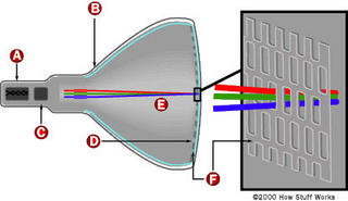

--------------------------------------------------------------------------------
11.1) No color - black and white picture
This means absolutely no color - equivalent to a black and white picture.
Not even a hint of color.
First, confirm that the source is actually in color - try another channel
or input device.
Next, check the settings of the color control - it may have accidentally
been turned down. If your TV has some kind of automatic picture mode,
try turning if off and adjusting the color control. Try adjusting fine
tuning if you have such a control and the problem is with a broadcast
or cable transmission.
At this point with a confirmed color signal source, there is a problem
with the chroma circuitry.
Note that to the average person, the obvious question becomes: is my color
picture tube bad? The answer is a definitive NO. It is virtually impossible
for a defective CRT to cause a total loss of color. A defective CRT can
cause a lack of a primary color - R, G, or, B or a short between two colors
which will mess up the color but is not likely to result in a black and white
picture.
Some possibilities in no particular order:
1. Weak signal or defect in tuner/IF causing loss of signal strength.
2. Coler killer set too high (internal control) if it has one.
3. Defective part around the chroma chip/circuit. Faulty color
oscillator.
4. Bad connections in area of chroma chip/circuit.
5. Defective chroma chip (don't suspect this first just because it
is probably very expensive).
A service manual or Sams', DMM, & scope will help greatly in attempting to
troubleshoot this unless it is an obvious bad connection. Try prodding
the main board around the chroma chip with an insulated tool to see if
you can make the color come and go.
I had one set where a $.02 resistor decided to open up causing just this
problem - perfect BW picture, no color. Another had a coil with a broken wire.
--------------------------------------------------------------------------------
11.2) Saturated color but almost no brightness
This means you have lost the luminance input to the chroma decoder or final
video chip. A failure of the brightness limiter may result in similar
symptoms.
A few common causes are:
* Check the service switch (if any). Its contacts may be dirty and moving it
back and forth a few times or using contact cleaner may be all that is
needed.
* Check for open high value resistors around the chroma decoder IC.
* Check for open high value resistors in the brightness limiter circuit.
With a scope and schematic (or even just a pinout for the chip), you should be
able to trace the luminance signal to see where it is getting lost.
This is also *not* a picture tube problme :-).
--------------------------------------------------------------------------------
11.3) Brightness control has no effect
The following assumes that the picture is fine but the brightness is
fixed - probably at too high a level. However, there could be several
interrelated problems if a common supply voltage were missing, for example.
If it is a knob, then it should be varying the control grid (G1) voltages
relative to the cathodes (K) of the CRT. This is not likely to be a very
complex circuit. If you do not have a schematic, I would start by tracing
from the control, check continuity and solder connections. Check the
control itself for proper operation with an ohmmeter. A power supply going
to one side of the control (negative probably) may be missing. Tbe control
grid voltage will end up on the little board on the neck of the CRT - check
there as well for bad solder connections or open resistors.
If brightness is a digital control, then you will need a schematic unless
there is an obvious bad connection.
--------------------------------------------------------------------------------
11.4) One color is too weak or too strong
If the problem is slight and/or has gradually gotten worse, this may just
require an adjustment of the color brightness/background/bias and/or color
gain/drive controls inside the TV. See the section: "Color balance adjustment".
Note that if it is possible to obtain a good black and white picture with the
user color control set to its minimum, then this is not likely a problem with
one of the primary color channels (red, green, or blue) but with the chroma
decoding circuitry. Or, perhaps, you are just watching MTV!
Even if it appears as though there is an excess, this may actually be a
reduction in one of the primary colors. For example, a magenta tinge is
represents a reduction in the strength of the green signal.
* Too high an intensity for one of the color channels will result in a tint of
one of the primaries: red, green or blue.
* Too low an intensity for one of the color channels will result in a tint of
the complement of one of the primaries: yellow, cyan, or magenta.
* Problems mainly in the shadows or dark areas of the picture usually represent
a fault with brightness/bias/background.
* Problems mainly in the highlights or bright areas of the picture usually
represent a fault with the gain/drive.
A color that that is now suddenly brighter or darker than normal resulting in
incorrect color balance or a tint in the background could be due to a number
of causes:
* Bad connections or bad component in video amplifier or on CRT neck board for
that color.
* Fault in chroma decoder.
* Weak gun in CRT (reduced color).
--------------------------------------------------------------------------------
11.5) Psychodelic color
The means colors that are not normal and that adjustment of the user
controls is not able to correct it so that all colors of the picture
are properly displayed at the same time. For example, you are unable
to get any yellows or blues in scenes that should have these colors..
Make sure the user color and tint controls have not been accidentally
turned while cleaning or purposedly misadjusted by small (or large) kids.
Perform the user setup described in the section: "User picture adjustment".
Confirm that the source is not a weird color video - try another
channel or a tape.
Verify that this is not a missing color problem - one of the primary R, G,
or B, has disappeared. If so, refer to the section: "Intermittent or missing colors".
Once these have been eliminated, you are left with the
following possibilities:
1. Defective part around the chroma chip/circuit. Misadjusted color
oscillator.
2. Bad connections or short circuit in area of chroma chip/circuit.
3. Defective chroma chip (don't suspect this first just because it
is probably very expensive).
4. Bad degauss circuit resulting in lack of degauss or abrupt termination
of degauss current rather than smooth tail off. The CRT is not being
properly demagnetized and color purity is totally messed up.
5. Bad CRT - the shadow mask has been damaged and it is impossible to
properly adjust purity across the screen.
A service manual or Sams', DMM, & scope will help greatly in attempting to
troubleshoot this unless it is an obvious bad connection. For (1)-(3),
try prodding the main board around the chroma chip with an insulated tool
to see if you can restore normal color. For (4) try manually degaussing
(see the section: "Degaussing (demagnetizing) a CRT". If this clears up
the colors until at least when it is power cycled, then a degauss problem
is likely.
Something as simple as a bad resistor or inductor can be the cause - don't
immediately suspect the most expensive and difficult to replace part.
--------------------------------------------------------------------------------
11.6) No picture/dark picture/erratic picture
Remove the picture tube socket (carefully!) and clean the pins with fine
sandpaper and use contact cleaner on the socket. This source of bad
connections can result in a variety of erratic symptoms.
--------------------------------------------------------------------------------
11.7) TV and Monitor Manufacturing Quality and Cold Solder Joints
Any intermittent problems with monitors that cause random sudden changes in
the picture brightness, color, size, or position are often a result of
bad connections.
Bad solder joints are very common in TVs and monitors due both to poor quality
manufacturing as well as to deterioration of the solder bond after numerous
thermal cycles and components running at high temperature. Without knowing
anything about the circuitry, it is usually possible to cure these problems
by locating all bad solder connections and cleaning and reseating internal
connectors. The term 'cold solder joint' strictly refers to a solder
connection that was either not heated enough during manufacturing, was
cooled too quickly, or where part pins were moved before the solder had
a chance to solidify. A similar situation can develop over time with
thermal cycling where parts are not properly fastened and are essentially
being held in by the solder alone. Both situations are most common with
the pins of large components like transformers, power transistors and
power resistors, and large connectors. The pins of the components have
a large thermal mass and may not get hot enough during manufacturing. Also,
they are relatively massive and may flex the connection due to vibration
or thermal expansion and contraction.
To locate cold solder joints, use a strong light and magnifier and examine
the pins of large components for hairline cracks in the solder around the
pin. Gently wiggle the component if possible (with the power off). Any
detectable movement at the joint indicates a problem. With the power on,
gently prod the circuit board and suspect components with an insulated
tool to see if the problem can be effected.
When in doubt, resolder any suspicious connections. Some monitors may
use double sided circuit boards which do not have plated through holes.
In these cases, solder both top and bottom to be sure that the connections
are solid. Use a large enough soldering iron to assure that your solder
connection is solid. Put a bit of new solder with flux on every connection
you touch up even if there was plenty of solder there before.
--------------------------------------------------------------------------------
11.8) Why can't TV manufacturers learn to solder properly?
I can think of several potential reasons - all solvable but at higher
manufacturing cost.
1. Mass of large component leads (like shields) does not get adequately
heated during manufacture leading to latent cold solder joints. While
they may look ok, the solder never actually 'wetted' the heavy pins
and therefore did not form a good mechanical or electrical bond.
2. Thermal cycles and differential thermal coefficients of circuit boards,
traces, and solder. While it is not easy to do anything about the
material properties, using plated through-holes or a similar mechanical
via would greatly increase the surface area of the joint and prevent
the formation of cracks.
3. Vibration. This is also directly related to the single sided circuit
boards without plated through-holes to strengthen the joints.
4. Lack of adquate mechanical support (single sided circuit boards without
plated through-holes (vias).
I believe that the single most significantimprovement would come about
by using plated trhough-holes but this would add to the cost and apparently
the consumer is not willing to pay more for better quality and reliability!
Some designs have used rivlets - mechanical vias instead of plated ones.
While this is good in principle, the execution has often been flawed where
cold solder joints resulted between the rivlets and the circuit board traces
due to lack of adequate process control.
The Sony and RCA/GE tuner shield problem is interesting because this
could have been solved years ago at essentially no additional cost as
other manufacturers - and their own repair procedures - have proven.
--------------------------------------------------------------------------------
11.9) Intermittent or missing colors
This is a catch-all for some of the most common TV and monitor problems.
* If gently whacking the set can make the color(s) come and go suddenly, then
bad connections are probable. The most likely place for these are solder
pads on the little circuit board on the neck of the CRT or even dirty CRT
socket pins that are not making solid contact. Try prodding the CRT neck
board with an insulated stick to see if you can affect the colors.
Although not impossible, this is not likely to be a CRT problem.
* If the color fades in and out with a delay of about 10-15 seconds, it is
probably intermittent power to the CRT filament for that color and probably
means a bad CRT since the three filaments are wired in parallel inside the
CRT. One of the internal connections has come loose.
Look in the neck of the CRT to make sure all three filaments are glowing
orange. If one is out or goes on and off, toss the set. Replacing the CRT
is probably not worth it. However, if they all go on and off together (all
colors would be fading in and out though perhaps not quite in unison), then
bad connections for the CRT filaments on the CRT neck board are indicated.
To narrow down the problem:
* Locate the output for the bad color on the video driver board on the
neck of the CRT. This will probably read a significantly higher
voltage than the corresponding pins for the good colors. A circuit
problem is likely - probably on this board.
* Test components on this board for the good and bad color channels. A
shorted transistor or open resistor can kill one channel. Swap parts
between good and bad colors to confirm.
* Gently pull the CRT neck board off of the CRT and replace it. This will
tend to clean the contacts.
* Connect an output of the video/chroma circuit/chip that is working (i.e.,
a color that appears on the screen) to *all* three color drivers on the CRT
neck board.
- If you now get a more-or-less black and white picture (there may be a
moderate color tint as the relative intensities of R,G,B may not be
balanced), the problem is likely with the chroma decoder or its support
circuitry.
Note: the picture will be the intensity of only one color channel so it
will not be quite *normal* in any case.
- If you still have missing or messed up colors, the problem is on the CRT
neck board or with the CRT.
Most of the causes of intermittent colors boil down to bad connections
of one form or another. For totally dead colors - not intermittent - bad
components are also a possibility.
* Printed circuit board on the CRT neck. This is a common location for
cold solder joints. Check with a bright light and magnifying glass
for hairline cracks around the pins of larger parts. Prod and tap with
an insulated tool to see if the problem is effected. Resolder if necessary.
* Cold solder joints elsewhere in TV or monitor usually around the pins of
large parts such as transformers, power transistors and resistors, and
internal connectors.
* Internal connectors (including CRT socket) that need to be cleaned and
reseated. Remove, clean with contact cleaner, burnish, and replace.
--------------------------------------------------------------------------------
11.10) Some commentary on monitor and TV whacking
Anytime that intermittent symptoms are experienced, I recommend gently
whacking the patient to determine if mechanical shock or vibration affects
the behavior. Here are a couple of responses to this suggestion.
(The following is from Marc Gelfond (71363.1700@CompuServe.COM)):
I just love the bit about "whacking it". It brings to mind an
episode from the old Andy Griffith show, where a new fangled piece
of electronics gear, was broght into Emmets repair shop. After
many long hours of fruitless troubleshooting, out of frustration
Emmet gave the thing a whack, and sure enough it fixed the problem.
As we say in the Telephony business, it "CCWT" or Came Clear While Testing.
Another saying is that it "CCBFM" Came Clear By F------ Magic!!
(To which Gavin Adams (gaa@hopi.com) comments):
In the video industry we had a saying concerning malfunctioning gear:
"If it's broke, hit it with a hammer"
"If that doesn't fix it, paint it and sell it"
My DEC 16" monitor is case in point. Evey once in a while it would lose sync,
and smacking it would bring it back (sometimes a few smacks). Recently it
gave up the ghost completely, and after the local DEC office gave me a quote
of $900 to fix it (Bermuda), I ordered a new Viewsonic 17" for the same price.
I ripped the guts out of the DEC beast, painted it with a marble finish, put
plants in it, and sold it! :>
--------------------------------------------------------------------------------
11.11) Retrace lines in picture
During the time the electron beam is returning from right to left at the end
of a line and bottom to top (over the course of multiple lines), it is supposed
to be result in no visible light on the screen. However, a number of faults
can result in visible retrace lines.
The appearance will likely be a general reduction in contrast from the visible
horizontal retrace on every scan line and two dozen or so diagonal lines lines
(lower left to upper right) resulting from the vertical retrace.
The retrace lines may be either white or gray (possibly with a slight color
tint due to unequal settings of the color adjustments) or a primary color -
red, green, or blue. Anything in between is also possible but less likely.
--------------------------------------------------------------------------------
11.12) White/gray retrace lines
Where all colors are involved - the lines are essentially white or gray (or
with a slight tint due to slight unequal settings of the color adjustments),
look for something common like an incorrectly adjusted screen (G2) or master
brightness/background/bias control or a problem in one of these circuits, a
defective power supply or a problem in the blanking circuitry:
* Screen (G2) or master brightness/background/bias control - mark setting and
then see if a slight adjustment removes the retrace lines. See the chapter:
"TV Adjustments". Of course, if this happened suddenly, the problem is not
due to a misadjusted control though a dirty pot is possible - turn it back
and forth - this might clean it and restore normal operation.
* Power supply or connection to CRT neck board - insufficient voltage will
result in the CRT never totally blanking. Check (usually scan derived)
power supply components (from flyback).
* General power supply - check B+ for correct value and ripple. A main power
supply fault might result in these symptoms (and usually many others).
* Blanking circuit - this may be a part of the video/chroma chip or separate.
Check waveforms to determine if the blanking pulses are making it to the
video output.
--------------------------------------------------------------------------------
11.13) Red, green, or blue retrace lines
Where only one color is showing, suspect an incorrectly adjusted individual
background/bias control or bad part on the CRT neck board for that color.
* Individual brightness/background/bias control(s) - mark setting of pot for
the problem color and then see if a slight adjustment removes the retrace
lines. See the chapter: "TV Adjustments". Of course, if this happened
suddenly, the problem is not due to a misadjusted control though a dirty
pot is possible - turn it back and forth - this might clean it and restore
normal operation.
* Component or connection on CRT neck board - insufficient voltage to or
incorrect biasing of the video driver for this color can result in the
CRT never totally blanking. Compare voltages and signals, and swap
components between good and bad channels to confirm.
* Blanking circuit - this may be a part of the video/chroma chip or separate.
Check and compare waveforms of good and bad colors to determine if the
blanking pulses are making it to the video output.
There is a slight possibility that a bad CRT may result in visible retrace
lines. To eliminate this possibility:
* Disconnect the filament - all evidence of a picture, raster, and retrace
lines should disappear once the filaments/cathodes have cooled (15 seconds
or so. If there are still visible retrace lines, the CRT is suffering
from cold or field emission from someplace (may not even be the cathode).
* Turn down the screen (G2) control on the flyback (usually). If one color
remains no matter how you set the control, again there is some kind of
weird emission from the CRT. However, if white/gray retrace lines remain,
the problem may be in the screen supply.
See the section: "Bad CRT causing retrace lines".
--------------------------------------------------------------------------------
11.14) Bad CRT causing retrace lines
(From: Jeroen H. Stessen (Jeroen.Stessen@ehv.ce.philips.com)).
The TV which I bought last started developing retrace lines after a month or
so of use. I took it back to the lab for warranty (special deal) and had it
examined by the real experts. They found that even with the filament supply
disconnected and VG2 at 0V the screen would still light up. They could even
see that the electrons weren't even coming from the cathode. That was with
only the picture tube in a test rig. So in this case the obvious conclusion
had to be that the tube was bad, and it was replaced (32" 16:9 SF, very $$).
It had something to do with processing problems during manufacturing of the
electron guns.
So even if this was a rare case, it *can* happen that retrace lines are due
to a bad picture tube. It's more usual to suspect the VG2 (screen voltage)
or a defect somewhere in the RGB video path.
--------------------------------------------------------------------------------
11.15) Red, green, or blue full on - fog over picture
This could be a heater-cathode (H-K) short in the CRT or a failure
of a component in the chroma circuits or video output (driver board).
Don't panic - heater-cathode shorts in CRTs can often be worked around.
Note: before proceeding, it is a good idea to make sure that the screen is
degaussed - else you could be attempting to track down problems with the wrong
color!
Some simple tests can confirm or rule out other possibilities.
* Compare the voltages for the video drive signals to the CRT on the little
board on the neck of the CRT with the CRT both connected and unplugged.
A schematic will help greatly in locating these signals.
- If there is a significant difference especially on the bad color, then the
CRT is a likely candidate. Try tapping the neck of the CRT GENTLY (with
it plugged in and while viewing a picture) to see if it is an intermittent
problem.
- If there is no significant difference, you may have a bad driver or a
problem in the chroma circuits.
* Look for bad connection/cold solder joints, probably on the little
board on the neck of the CRT. Use an insulated stick to gently prod
the board and its components in an effort to induce/cure the problem.
Look carefully for hairline cracks around the component leads.
* You can swap components between two colors and/or test with an ohmmeter
on that driver board to determine what is bad. The nice thing about
color monitors and TVs is that there three copies of each of these
components. Swapping and/or comparisons between these is an excellent
diagnostic technique.
* Another simple test: Disconnect the cathode for the full-on color from its
drive. If it is still full-on, there is probably an H-K short in the CRT
since the only way to get each color on the screen is via the cathode
connection to the CRT neck board. If it is removed and there is still that
color, the current must be taking another path inside the CRT.
* Alternatively, interchange the outputs of the bad color with a good one
by jumpering on the video driver board (on the CRT neck). If the bad
color changes, then the problem is in the circuitry and not the CRT.
Here is the procedure in more detail (example for red full on):
(From: J. K. Emerine (jkemerine@aol.com)).
To identify if the fault is in the crt or a control problem try this (WITH
SET OFF):
On the CRT board, lift the output end of the green cathode final resistor.
Do the same with the offending red cathode's resistor. Use short insulated
jumpers to 'swap' drive signals - drive the red cathode with the green
drive and the green cathode with red drive. (Note that if this problem
only occurs after a warmup period, color at turn on will be - well - wierd,
but it is just a test.)
- If the symptom returns = 'goes red' the CRT is shorting. (See the section:
"Providing isolation for a CRT H-K short". --- sam)
- If instead the symptom becomes 'goes green' then the red drive leg has
the fault and the CRT is probably good. (In this case, there may be bad
connections or a bad component on the CRT drive board or further back
in the chroma circuitry. --- sam)
--------------------------------------------------------------------------------
11.16) Shorts in a CRT
Occasionally, small conductive flakes or whiskers present since the day of
manufacture manage to make their way into a location where they short out
adjacent elements in the CRT electron guns. Symptoms may be intermittent or
only show up when the TV or monitor is cold or warm or in-between. Some
possible locations are listed below:
* Heater to cathode (H-K). The cathode for the affected gun will be pulled
to the heater (filament) bias voltage - most often 0 V (signal ground). In
this case, one color will be full on with retrace lines. Where the heater
is biased at some other voltage, other symptoms are possible like reduced
brightness and/or contrast for that color. This is probably the most
common location for a short to occur.
* Cathode to control grid (K-G1). Since the G1 electrodes for all the guns
are connected together, this will affect not only the color of the guilty
cathode but the others as well. The result may be a very bright overloaded
*negative* picture with little, none, or messed up colors.
* Control grid to screen (G1-G2). Depending on circuitry can result in any
degree of washed out or dark picture.
* Screen to focus (G2-F). Screen (G2) and focus voltage will be the same and
the controls on the flyback will interact. Result will be a fuzzy white
raster with retrace lines and little or very low contrast picture. Symptoms
will be similar to those of a flyback with breakdown in the focus/screen
divider network.
* Focus to high voltage (F-HV). High voltage will be pulled down - probably
arcing at the focus spark gaps/other protective devices. Line fuse and/or
HOT may blow.
* Other locations between electron gun elements as feed wires.
Replacing the CRT may be required but there are a variety of 'techniques' that
can often be used to salvage a TV that would otherwise end up in the dump
since replacing a CRT is rarely cost effective:
1. Isolation - this will usually work for H-K shorts as long as only one gun
is involved.
2. Blowing out the short with a capacitor - depending on what is causing the
short, this may be successful but will require some experimentation.
3. Placing the CRT (TV or monitor) face down on a soft blanket and *gently*
tapping the neck to dislodge the contamination. Depending on the location
of the short, one side or the other might be better as well. Sometimes,
this can be done in-place while watching the picture.
A combination of (2) and (3) may be required for intermittent shorts which
don't appear until under power. See the sections below for additional
details. However, for shorts involving the focus and high voltage elements,
even a sharp edge can result in arcing even if there is no actual short.
There is no remedy for these types of faults.
--------------------------------------------------------------------------------
11.17) Providing isolation for a CRT H-K short
This procedure will substitute a winding of your own for the one that is
built in to the flyback to isolate the shorted filament from the ground
or voltage reference. Note that if you have a schematic and can determine
where to disconnect the ground or voltage reference connection to the
filament winding, try this instead.
The flyback is the thing with the fat red wire coming out of it (and perhaps
a couple of others going to the CRT board or it is near this component
if your set has a separate tripler) and may have a couple of controls for
focus and screen. It should have some exposed parts with a ferrite core
about 1/2-3/4" diameter.
The filament of the CRT is the internal heater for each gun - it is what
glows orange when the set is on. What has happened is that a part of the
fine wire of the bad color's filament (assuming this is indeed your problem)
has shorted to the cathode - the part that actually emits the electrons.
Normally, the heater circuit is grounded or tied to a reference voltage
so when it shorts to the cathode, the cathode voltage level is pulled to
ground or this reference.
You will need some well insulated wire, fairly thick (say #18-22). Find a
spot on the flyback where you can stick this around the core. Wrap two
turns around the core and solder to the CRT filament pins after cutting the
connections to the original filament source (scribe the traces on the board
to break them). Make sure you do not accidentally disconnect anything else.
This winding should cause the filaments to glow about the same brightness as
before but now isolated from ground. If they are too dim, put another turn
on the flyback to boost the voltage as this will result in low emission,
blooming, and possible damage to the cathodes after awhile. (Don't go
overboard as you may blow the filament totally if you put too many turns on
the core - you then toss the TV.)
Route the wires so that there is no chance of them getting near the high
voltage or any sharp metal edges etc. Your picture quality may be a tad
lower than it was before because of the added stray capacitance of the
filament wiring being attached to the the (formerly bad) video signal, but
hey, something is better than nothing.
If you are not inclined to build your own isolation transformers, kits are
available:
(From: Alan Harriman (capstv@sprynet.com)).
A company called KDTV/IWE carries kits (core, wire and tie) for $3.30 each.
It takes all of two minutes to wind.
Check out: http://www.seidata.com/~kdtv.
BTW, I am just a satisfied customer.
--------------------------------------------------------------------------------
11.18) Rescuing a shorted CRT
If the short is filament-cathode (H-K), you don't want to use the following
approach since you may blow out the filament in the process. If this is the
case, you may be able to float the filament and live with the short (see the
section on: "Red, green, or blue full on - fog over picture".
Shorts in the CRT that are between directly accessible electrodes can
be dealt with in a more direct way than for H-K shorts. At this point
you have nothing to loose. A shorted CRT is not real useful.
If the short is between two directly accessible electrodes like cathode-grid,
then as a last resort, you might try zapping it with a charged capacitor.
Start with a relatively small capacitor - say a few uF at a couple hundred
volts. Check to see if the short is blown after each zap - few may be needed.
Increase the capacitance if you fell lucky but have had little success with
the small capacitor.
If the fault is intermittent, you will, of course, need to catch the CRT
with the socket disconnected and the short still present. Try some gentle
tapping if necessary. If you do this with the charged capacitor across
the suspect electrode, you **will** know when the short occurs!
--------------------------------------------------------------------------------
11.19) Picture tube replacement
It is possible to replace the picture tube. However, this is likely to
be both expensive and possibly time consuming with respect to adjustments
like purity and convergence. When replacing:
* Discharge both the old and new tubes before you start to be sure you won't
have any unpleasant surprises.
* Take extreme care when handling - at the very least, a slip can result in a
broken neck and a bad and expensive day.
"The 25VCXP22 picture tube of my RCA Accutouch XL-100 CCU-942 TV start fading.
Its 100% transistorized, everything still works perfectly after about 20
years service. but:
* Can I still buy new RCA 25VCXP22 picture tube? What is the approximate cost?
* Any equivalent tube for direct replacement? Cost?
* If no replacement picture tube is available, what is other option?"
(From: Chris Jardine (cjardine@wctc.net)).
What you have here is genericly referred to as the 25V as opposed to the 25A
picture tube. While there are minor differences with respect to the letters
after the V for the most part they are interchangeable. When I worked my way
through engineering college I worked at a TV repair shop and my job was mostly
changing picture tubes. Yeah, we did enough of them to keep a tech busy 4 to 5
hours a day changing them and I got pretty good and could change, color
balance, convergence, etc. the tube in about 45 minutes. We for the most part
used 3 major tubes, 1) 25A, 2) 25V, and 3) 21FJ (a little nostalgic for those
who remember this one). This was back when your TV would have been fairly new
(1981 to 82). These are available from many different sources - RCA, Channel
Master, Wisconsin Tube, etc. The price would vary depending on the quality of
the tube. I remember that we could get a 25A for about $35 at the time due to
our volume - one truck per month. The most expensive I've seen them has been
just over $200. This is quite a range and there are now many other types of
tubes including in-line, trinitron, etc.
I hope this helps and thanks for the trip down memory lane!
(From: Chris Jardine (cjardine@wctc.net)).
The important thing here is that the tube begins with 25V. If it does it should
work in your set. The only thing you have to know is whether the tube has
'ears' attached permanently. The 25V comes both with and without these mounting
ears permanently attached. I know that you can still get one of these from any
of a number of suppliers. I know that Channel Master and RCA (Thompson,
whatever!) still make them available as well as any of a number of local CRT
rebuilders.
--------------------------------------------------------------------------------
11.20) Dark picture
A TV or monitor with a picture that is too dark may have a fault or the CRT may
just be near the end of its useful life.
First, confirm that your video source - computer, camera, etc. - is producing
a proper signal.
Is the brightness at all erratic? Does whacking the monitor have any effect?
If so, then you may have bad connections on the CRT driver card or elsewhere.
If the brightness tends to fade in and out over a 10 to 20 second period,
a bad filament connection is likely. Check for the normal orange glow of
the filaments in the neck of the CRT. There should be 3 orange glows. If
they are excessively reddish, very dim, or fade in and out, you have located
a problem. See the section: "Picture fades in and out".
Common causes of brightness problems:
0. Dirty CRT faceplate or safety glass. Don't laugh. It sounds obvious, but
have you tried cleaning the screen with suitable screen cleaner? It is
amazing how dirty screens can get after a few years - especially around
smokers!
Wipe gently with a slightly dampened cloth - not soaking or you may end
up with real problems when the water drips down inside and hits the
electronics! On TVs with a separate protective faceplate, clean both
the front and rear surfaces of this plate as well as the CRT itself.
1. Old CRT. The brightness of the CRT deteriorates with on-time. It does not
matter much how bright your run your TV. An indication of a weak CRT would
be that turning up the SCREEN (G2) or master brightness control only results
in a not terribly bright gray raster before the retrace lines show up.
There may be indications of poor focus and silvery highlights as well. A
CRT brightener may help. See the section: "Brightening an old CRT".
2. Bad component in filament circuit or bad connection reducing filament
voltage. This should be easy to check - there are only a few parts
involved. If it is erratic, bad connections are likely.
3. Brightness control faulty - bad pot, bad connections, or problem with its
power supply. Depending on specific problem, control may or may not have
any effect. If digitally adjusted, there could be a problem with the
logic or control chip. If the button or menu item has no effect at all,
then a logic or control problem is likely.
4. Improperly set SCREEN (G2) voltage (usually on flyback) or faulty divider
network. See the section: "Adjustment of the internal SCREEN and color controls".
5. Improperly set video bias (background) levels or fault in video drive
circuitry. See the sections starting with: "Optimal procedure for setting brightness/background and screen adjustments".
6. Fault in video amplifiers. With all three color affected equally, this
would most likely be a power supply problem. A video amplifier problem
is likely if turning up the SCREEN (G2) or master brightenss control
results in a very bright raster before the retrace lines appear. Cheack
signals out of the video/chroma(IC.
7. Fault in beam or brightness limiter. Many TVs and monitors measure the
beam current (possibly indirectly) and limit the maximum to a safe value.
The purpose of this may be to protect the CRT phosphors, and/or to assure
that the power supply does not go out of regulation, and/or to limit X-ray
emission. If this circuit screws up, a dark picture may result. Checking
the signals and voltages at the CRT socket should determine if this is the
problem.
8. High voltage is low. However, this would likely result in other symptoms
as well with focus, size, and geometry.
--------------------------------------------------------------------------------
11.21) Brightening an old CRT
If performing adjustments of the internal background and/or screen controls
still results in a dark picture even after a long warmup period, the CRT
may simply be near the end of its useful life. In the old days of TVs
with short lived CRTs, the CRT brightener was a common item (sold in every
corner drugstore, it seemed!).
You can try a similar approach. Caution: this may shorten the life of
the CRT - possibly quite dramatically (like it will blow in a couple of
seconds or minutes). However, if the monitor or TV is otherwise destined
for the scrap heap, it is worth a try.
The approach is simple: you are going to increase the voltage to the
filaments of the electron guns making them run hotter. Hopefully, just
hotter enough to increase the brightness without blowing them out.
Voltage for the CRT filament is usually obtained from a couple of turns
on the flyback transformer. It is usually easy to add an extra turn or two
which will increase the voltage and thus the current making the filaments
run hotter. This will also shorten the CRT life - perhaps rather drastically.
However, if the TV or monitor was headed for the dumpster anyhow, you have
nothing to lose.
--------------------------------------------------------------------------------
11.22) Picture tube brightener
(From: Kevin Carney (carneyke@mhv.net)).
Try a CRT brightener from MCM Electronics about $20. It boosts the
filament voltage a volt or two. I have used them before and they help.
You can also try running a power supply on the filament with the
monitor OFF. Set the supply at the filament voltage and slowly bring
the voltage up. If the filament is 6.3 volt bring it up gradually to
10 -12 volts for about a half hour. This will brighten it up some.
Be careful because too much voltage can open the filament !
Before doing this did you check the screen voltage setting and the
RGB settings for drive and background ?
There are also commercial CRT rejuvenators that supposedly zap the
cathodes of the electron guns. A TV repair shop may be able to
provide this service, though it is, at best, a short term fix.
--------------------------------------------------------------------------------
11.23) More drastic measures to brighten CRT
(From: LEE (leep@mailhub.scf.lmsc.lockheed.com)).
As a start, I crank the brightness control all of the way up. I then turn the
color control all of the way up. I let the set run with a bright screen for
around 15 min. This procedure cleans up the cathode surfaces so that they can
emit more electrons. Now turn the controls back to normal and see if any
improvement took place. If not, Wrap 2 or 3 turns of around 18 gauge insulated
wire around the flyback and add this extra power in series with existing
filament leads from flyback. You can experiment with the number of turns etc.
to get brighter filaments. do not run the filaments white - just a brightened
yellow. This will probably turn out to be around 8-9v in most cases. I had to
do this on two different Sanyo replacement flybacks as they had low filament
voltage from the factory. (flakey replacement parts). I`ve been running one of
these Sanyos for around 4 years now with a nice bright picture (13")
--------------------------------------------------------------------------------
11.24) Left portion of screen is dark or faded
"I've got an old TV where the left 1/3 of the screen is 'faded'. It is
especially noticable when a dark picture is showing (like a night time
scene)."
This is normally caused by a bad filter capacitor on the power supply line
(typically 200 V) that feeds the RGB output transistors. It is usually a scan
derived voltage off of the flyback. Look for an electrolytic capacitor of
around 4.7 to 10 uF, 160 to 250 V fed from a rectifier diode on this supply.
--------------------------------------------------------------------------------
11.25) Color balance changes across screen from left to right
The characteristics are that a solid white screen will tend to be blue tinted
on one side and red tinted on the other. This is usually a subtle effect and
may be unavoidable with some designs.
There are several possibilities:
1. Purity - this means the beams are landing on the wrong phosphor dots.
This is what would be affected by moving from one location to another
or even rotating the TV on its base without degaussing. If the problem
just appeared, degaussing may be needed.
What do you have near the TV or monitor? Loudspeakers or other devices
which generate magnetic fields can easily cause all sorts of color purity
problems. Relocate the offending device(s) or the TV or monitor and then
degauss it.
See the section: "Degaussing (demagnetizing) a CRT".
If the problem still persists, purity adjustment may be needed. However,
this isn't likely to have changed so look for other causes before tackling
these adjustments.
2. Unequal electron gun to shadowmask/screen distance - the electron beams for
the red and blue video travel slightly different distances on the left and
right sides of the screen so their intensity (due to focus not being optimal
and other factors) in each case may differ slightly affecting color balance.
3. Doming - This would only happen in very bright areas and causes the
shadow mask to expand and distort. (Doming should not be a problem with
Trinitron CRTs which use tensioned wires in their aperture grill.) This
would also not really affect left-right color balance in particular.
I don't really know how much of a problem (2) is in practice or whether some
manufacturers compensate for it.
--------------------------------------------------------------------------------
11.26) Bleeding highlights
On very bright areas of the picture, one or more colors may bleed to
the right resulting in a trail of those colors. The difference between
this problem and the section: "Trailing lines in one or more colors" is
that in this case, only highlights are affected.
One cause of this is that the color gain, contrast, or intensity controls
(whatever they are called on your set) are set too high. See the section
on: "Color balance adjustment". Check the settings of any brightness limiter
controls as well.
--------------------------------------------------------------------------------
11.27) Trailing lines in one or more colors
Assuming this is not a form of ghosting resulting from poor reception
conditions, then it could be any of the following:
* Poor decoupling in the power supplies for the video drive circuits - probably
on the CRT neck board. Check for bad (low uF or high ESR) filter capacitors
(electrolytic mostly) on this board or the power supplies feeding it.
* Insufficient CRT filament voltage. This could be a result of bad connections
or a bad component in the filament power supply (probably from the flyback).
Check to see if the filaments are glowing bright orange and check the voltage
if possible (though this can be tricky since it is often fed from a winding
on the flyback and is a pulse waveform, not DC or a sinusoid. The service
manual (or Sams' Photofact) will probably have info and waveforms.
* Bad CRT (more likely if only one color is affected). A weak electron gun can
result in this behavior. Swap it with one that work properly. If the same
color is still bad, that CRT gun is weak. The CRT will need rejuvenation or
need to be replaced (more likely, the entire TV will be tossed into the
dumpster).
--------------------------------------------------------------------------------
11.28) Brightness changes from left-to-right across screen
Slight variations in brightness across the face of the CRT are not unusual.
In fact, if you used a photometer to actually measure the brightness, you
might be amazed at the actual variance even with the best TV - you just
don't notice it. However, a major variation - usually a decay from left to
right but could be the other way indicate a component failure. Of course,
make sure the face of the screen is clean!
* A fault in the power supplies to the video amplifier and/or video output
circuits. Most likely, an electrolytic capacitor has dried up and is not
adequately filtering the power derived from the flyback which then has
ripple at the horizontal scan rate and thus locked to the screen. The
voltage decays from left-to-right between horizontal flyback pulses.
The most likely location for these capacitors is in the vicinity of the
flyback transformer on the mainboard or on the CRT neck board. Check the
capacitors with capacitor tester or ESR meter and/or take a look at the
power right at the video amplifier and video output drivers.
* Horizontal linearity is bad - this may actually be a horizontal geometry
problem and not a brightness problem.
See if objects on left side of the screen are stretched compared to those on
the right (or vice-versa). If they are, the problem is in the horizontal
deflection circuits - possibly a bad S correction capacitor or linearity
coil.
* Inoperative degauss circuit, TV moved or rotated without degaussing, or
magnetic field from some other device (like a permanent magnet) is affecting
CRT - slight amounts of magnetization may reduce brightness (by moving the
beams into the black space between phosphor dots) before affecting color
purity (where the beams land on the wrong phosphor dots).
Try deguassing manually. See the section: "Degaussing (demagnetizing) a CRT".
--------------------------------------------------------------------------------
11.29) Picture fades in and out
If the picture faded away on the order of 10-20 seconds (and if it comes
back, also comes up to full brightness in same time frame - possibly
with the persuasion of some careful whacking) AND with NO other
significant changes such as size, focus, etc., then take a look in the back of
the tube for the filament to be lit - the orange glow near the CRT socket. If
there is none, then you probably have a bad solder connection on the circuit
board on the neck of the CRT. Look for fine cracks around pins on that board.
Try prodding it with an insulating stick to see if the picture comes back.
Resolder if necessary. It is probably not a bad CRT as the filaments
are usually wired in parallel and all would not go bad at the same time.
However, if only a single color fades in and out, then a bad connection
inside the CRT is a distinct possibility - look for only one of the
filament's glow to be coming and going. This is probably not worth fixing.
If the picture faded away with other symptoms, then there is probably
a fault in the video amplifier/output one of its power supplies -
still probably a loose connection if you are able to get it back by
whacking.
--------------------------------------------------------------------------------
11.30) Occasional brightness flashes
These may last only a fraction of a scan line or much much longer.
This could mean an intermittent fault in a variety of places including
the video circuitry and SCREEN power supply:
* Brightness circuitry - SCREEN, master background or its power supply.
Could be in or around flyback or focus/screen divider. Could perhaps
be in the CRT, but probably less likely.
* Video amp before or at chroma demodulator - since after this point, you would
most likely get colored flashes since only one of the RGB signals would
likely be effected.
If you get it from all sources, then tuner/IF is ruled out.
Suppose you just have no signal to a direct video input. What do you
get? If you still get flashes, it should be real easy to monitor either
the video outputs or SCREEN supply (with a HV divider on your scope) for
noise. Then trace back to power or noise source.
--------------------------------------------------------------------------------
11.31) Excessive brightness and/or washed out picture
There are a number of possibilities including incorrect screen (G2) or bias
(G1) voltages, or a problem in the video or blanking circuitry. Any of these
could be the result of bad connections as well. A short in the CRT can also
result in these symptoms.
* Excessive brightness/washed out picture is often an indication of a
problem with the screen (G2) supply to the CRT. May be a bad capacitor
or resistor divider often in the flyback transformer assembly or on
the board on the neck of the CRT.
* If the excessive brightness just developed over time, then a simple
adjustment of the screen or background brightness controls may keep
it (and you) happy for a long time.
When good, a typical value would be in the 200 to 600 VDC at the CRT. The
screen (it may also be called master brightness, bias, or background) control
should vary this voltage. However, it may be difficult to measure as the
resistors in the voltage divider network may be quite large - hundreds of M
ohms. If your unit has an external screen control (less likely these days)
and it has no effect, trace out the circuitry in the immediate vicinity and
check the resistors and potentiometer for opens, look for bad connections,
etc. If it is built into the flyback transformer and is sealed, the entire
flyback will need to be replaced unless the actual problem turns out to be a
bad connection or bad component external to the flyback.
* Where the brightness control has no effect, suspect a missing bias supply to
the G1 (control grid) electrodes of the CRT. This is usually derived from
the flyback with a simple rectifier/filter capacitor power supply. Parts
may have failed (though not likely the flyback itself). Adjusting the user
brightness control should vary this voltage over a typical range of 0 to -50
V with respect to signal ground.
* It could also be a problem with biasing of the video output transistors.
There may individual controls for background brightness on the little board
on the neck of the CRT. However, we are looking for a common problem since
all colors are wrong in the same way. This is likely to be a missing voltage
from a secondary supply from the flyback.
* A short between electrodes inside the CRT can result in brightness problems.
It may be possible to check this with an ohmmeter with the power off and the
CRT socket removed. Test between G1, G2, and F where all colors are
affected though a short between F and G2 will result in the focus control
changing brightness and vice-versa - a classic symptom.
However, in some cases, it only shows up when operating and one must deduce
the presense and location of the short from its affect on voltages and bias
levels.
See the section: "Rescuing a shorted CRT" and other related topics.
First, check for bad connections/cold solder joints by gently prodding
with an insulating stick. Check voltages and bias levels.
--------------------------------------------------------------------------------
11.32) Bad focus (fuzzy picture)
Focus voltage on the CRT is usually in the range of 2-8 KV DC and should
be controllable over a fairly wide range by the focus pot - usually located
on the flyback or a little panel in its vicinity:
* If adjusting the pot results in a position of acceptable focus, you may be
done. It is not unusual for the focus setting to drift a over time.
* If the setting is already as good as possible but not really good enough,
the CRT may be tired. Alternatively, the filament voltage may be too low.
Check for bad connections in the filament circuit.
* If the optimal setting is out of range of the focus pot, the problem is
likely leakage in the focus divider in the flyback or one of the components
on the CRT neck board.
Also see the sections: "Focus adjustment" and "Focus drifts with warmup".
The focus wire usually comes from the flyback or if the general area or from a
terminal on a voltage multiplier module in some cases. It is usually a wire
by itself going to the little board on the neck of the CRT.
If a sparkgap (a little 2 terminal device with a 1/8" gap in the middle)
is arcing with power on, then the resistive divider has shorted inside
the flyback, focus board, or HV multiplier - whatever you TV has - and
the this unit will need to be replaced. Ditto if the SCREEN control affects
focus and/or vice-versa.
Using a suitable high voltage meter (range at least 10 KVDC, 1000 M ohm or
greater input impedance), you should be able to measure it connected and
disconnected. The ground return will be the outside coating of the CRT which
may or may not be the same as the metal chassis parts. If the voltage is very
low (less than 2 KV) and the pot has little effect:
* When measured right off of the source disconnected from the CRT neck board,
then the problem is probably in the focus network in the flyback (or wherever
it originates). Sometimes these can be disassembled and cleaned or repaired
but usually requires replacement of the entire flyback or voltage multiplier.
Note: you may need to add a HV (10 KV) capacitor between the focus wire and
DAG ground to provide filtering so you get a DC level for your meter.
* When measured with the focus wire attached to the CRT neck board with the
CRT connected but reasonable with the CRT unplugged, there is probably a
short between the focus and another electrode inside the CRT. See the
section: "Rescuing a shorted CRT".
* When measured with the focus wire attached to the CRT neck board with the
CRT unplugged, there is likely a component on the CRT neck board that is
leaky or breaking down. Also, check for decayed (tan or brown) glue which
may turn leaky with age.
--------------------------------------------------------------------------------
11.33) Focus drift with warmup
This could be due to a problem with the focus voltage power supply, components
on the CRT neck board, or a tired worn CRT.
Focus is controlled by a voltage of 2-8 KV DC usually derived from the flyback
transformer and includes some resistors and capacitors. One of these could
be changing value as it warms up. (assuming nothing else changes significantly
as the unit warms up - e.g., the brightness does not decrease.)
Focus voltage is derived from a subset of the high voltage winding on the
flyback using a resistive voltage divider which includes the focus pot.
These are extremely high value resistors - 200 M ohm is common - and so
leakage of any kind can reduce or increase the focus voltage. All other
things being ok - i.e., the picture is otherwise fine - I would suspect this
type of failure rather than the CRT.
The connection to the CRT is usually a separate wire running from the flyback
or its neighborhood to the CRT neck board. Look for components in this
general area. Use cold spray or a heat gun to isolate the one that is
drifting. If you have access to a high voltage meter, you should be able
to see the voltage change as the TV or monitor warms up - and when you cool
the faulty part. If it is in the flyback, then sometimes the part with the
adjustments clips off and can be repaired or cleaned. Most often, you will
need to replace the flyback as a unit.
* If the optimal adjustment point of the focus control doesn't change that
much but the best focus is simply not as good as it should be, the CRT is
probably the problem. However, if the optimal point produces acceptable
focus but it changes (and possibly moves off of one end of the adjustment
knob range) as the unit warms up, the flyback or one of the components on
the CRT neck board are likely drifting.
* If you have a high voltage meter, you can measure the focus voltage to
determine if it is being changed by the focus pot and if it is in the
ball park (2-8 KV typical). Sometimes, the part of the flyback with the
focus pot can be snapped off and cleaned or parts replaced but usually you
need to replace the whole unit. There may a capacitor or two on the PCB on
the neck of the CRT that could have increased leakage as well thus reducing
the focus voltage.
* To determine if the CRT is the problem, for sharp focus after the unit has
warmed up. Power-off for an hour or so and carefully pull the CRT neck board
off of the CRT. Then, power up the unit. Let it run long enough such that
there would have been a detectable focus drift. Now, power-down, plug the
CRT neck board back in, and power-up. Watch the image as it appears on the
screen:
- If the focus starts out fuzzy and sharpens up as the image appears and
gradually becomes sharper as the CRT warms up the CRT is likely tired.
The only catch here is that plugging the CRT neck board into the CRT
results in an additional load on the flyback due to the picture beam
current which heats it more as well. Thus, if the problem takes a few
minutes to appear, keep the brightness turned down except to check the
appearance of the picture from time to time.
You can set the focus control for optimum when warmed up and just turn
the TV on in well in advance of your favorite shows or add a user focus
adjustment by drilling a hole in the plastic case for an *insulated*
screwdriver or flyback focus knob extender :-). The CRT may continue
to function for quite a while so this is not impending doom.
- If the focus is relatively stable as the image appears and increases
in brightness *and* is about as sharp as it would be with the TV warmed
up, the problem is most likely in the flyback. However, also check for
bad components or decayed (tan or brown) glue on the CRT neck board. A
drifting flyback will need to be replaced as it will probably get worse
and fail completely. Clean the surface of the circuit board and CRT
socket in the vicinity of the focus and screen terminals and traces.
Contamination or just dirt and grime can easily cause problems especially
on humid days since the resistance of these circuits is extremely high
(100s of M ohms).
- If the focus is relatively stable as the image appears and increases
in brightness *and* is similar to what it would be with the monitor cold,
you have a very strange situation where some load on the high voltage
power supply, perhaps, is causing a thermal problem. This would be rare.
--------------------------------------------------------------------------------
11.34) Bad focus and adjustment changes brightness
This is the classic symptom of a short between the focus and screen
supplies - probably in focus/screen divider which is part of the flyback
or tripler. If you have a high voltage meter, measuring the focus voltage
will show that (1) it is low and (2) it is affected by the SCREEN control
Similarly, the SCREEN voltage will be affected by the FOCUS control (which
is what is changing the brightness.
There is a slight possibility that this may be in the CRT as well. Measure
the FOCUS and SCREEN voltage with a high voltage meter. If they are identical
pull the plug on the CRT. If they are now their normal values, then a
shorted CRT is a distinct possibility - see the section: "Rescuing a shorted CRT".
--------------------------------------------------------------------------------
11.35) Charlie's comments on focus problems
(From: Charles Godard (cgodard@iamerica.net)).
Most true focus problems that I have encountered (when the IHVT is ok) are
related to leaks or resistance on the focus output. The diming of the screen
when the focus pot is adjusted leads me to think in terms of a leaky socket.
I'd remove the ground from the crt socket to the tube dag and see if it
sparks. If so there may be a leak in the socket to ground. It could also be
leaking to another pin, such as the screen grid. A rhetorical question: What
happens to the screen voltage when the focus pot is adjusted?
I have seen sockets that had no arching or other telltale signs, leak through
the plastic housing to ground out the focus voltage.
Look closely at the screen. If the blurring is in the form of small circles,
then you have an open or hi-resistance focus electrode inside the tube. The
circles may vary in visibility with brightness.
If you still haven't found the problem, try to confirm that this is truly a
focus problem. Remove the crt socket and observe the hi-voltage. If it
climbs more than about 1k, say all the way up to 25kv, then you may have a
beam current problem rather than a focus problem. In that case re-check all
crt board voltages.
If you have done all of the above and removing the socket makes no change in
the hi-voltage, then try to determine why the hi-voltage is low.
Watch the screen as the brightness, contrast, or screen control are adjusted.
See if you can observe any signs of blooming. When the IHVT doesn't provide
enough current to satisfy the demands of the tube for current, the the picture
tends to appear to expand like a balloon. i.e., bloom. This can be caused by
not enough drive to the IHVT. Carefully monitor the b+ to the horizontal drive
stages to see that is is stable and correct.
--------------------------------------------------------------------------------
11.36) Blank picture, good channel tuning and sound
Since the tuner and sound are ok, horizontal deflection which usually
generates power for most of the set is also working.
Does 'blank picture' means a totally black screen with the brightness and
contrast controls having no effect whatsoever? Or, is there is no picture
but there is a raster - light on the screen? The direction in which
troubleshooting should proceed differ significantly depending the answer.
Here are some questions:
1. As above, is there any light on the screen at any settings of the brightness
and contrast controls, and/or when switching channels. Can you see any
raster scanning lines?
2. Can you hear the high pitched (15735 Hz) of the horizontal deflection?
3. Looking in the back of the set, can you see the glow of the CRT filament?
4. Do you get that static on the front of the tube that would indicate that
there is high voltage? Any cracking or other normal or abnormal sounds
or smells?
Possible causes of no raster:
* No or low high voltage (low voltage, deflection, or high voltage power
supply failure).
* Fault with other voltages like G1 or screen (G2) to CRT.
* Filament to CRT not getting powered.
* Drive to CRT bad/shut off as a result of fault elsewhere. For example,
failure of the vertical deflection may disable HV or blank the screem to
protect the CRT from burn-in due to the very bright horizontal line that
would result. With some sets, it is possible that the X-ray protection
circuitry will blank the screen without affecting tuning or audio.
Possible causes of no video (but a good raster): Problem in video IF, video
amplifiers, video output, cutoff due to other fault.
It could be as simple as a bad connection - try gently prodding the boards
with an insulated stick while watching the screen. Check for loose connectors
and reseat all internal connectors.
--------------------------------------------------------------------------------
11.37) Purple blob - or worse
Have you tried demagnetizing it? Try powering it off for a half hour, then
on. Repeat a couple of times. This should activate the internal degausser.
See the section: "Degaussing (demagnetizing) a CRT".
Is there any chance that someone waved a magnet hear the tube? Remove it
and/or move any items like monster speakers away from the set.
Was your kid experimenting with nuclear explosives - an EMP would magnetize
the CRT. Nearby lightning strikes may have a similar effect.
If demagnetizing does not help, then it is possible that something shifted
on the CRT - there are a variety of little magnets that are stuck on at the
time of manufacture to adjust purity. There are also service adjustments
but it is unlikely (though not impossible) that these would have shifted
suddenly. This may be a task for a service shop but you can try your
hand at it if you get the Sams' Photofact or service manual - don't attempt
purity adjustments without one.
If the set was dropped, then the internal shadow mask of the CRT may have
become distorted or popped loose and you now have a hundred pound paper
weight. If the discoloration is slight, some carefully placed 'refrigerator'
magnets around the periphery of the tube might help. See the section:
"Magnet fix for purity problems - if duct tape works, use it!"
It is even possible that this is a 'feature' complements of the manufacturer.
If certain components like transformers and loudspeakers are of inferior
design and/or are located too close to the CRT, they could have an effect
on purity. Even if you did not notice the problem when the set was new,
it might always have been marginal and now a discoloration is visible due
to slight changes or movement of components over time.
--------------------------------------------------------------------------------
11.38) Color rings - bullseye pattern
This probably means the degaussing circuitry is terminating suddenly instead
of gradually as it should. The most likely cause is a bad solder connection
to the degauss thermistor or posistor or something feeding it.
You can confirm this by manually degaussing the screen with the TV or monitor
turned on. If the problem disappears, the above diagnosis is probably valid.
Check for bad solder connections in the vicinity of the degauss components
and AC line input.
--------------------------------------------------------------------------------
11.39) Magnet fix for purity problems - if duct tape works, use it!
The approach below will work for slight discoloration that cannot be eliminated
through degaussing. However, following the procedures in the section: "CRT purity adjustment" would be the preferred solution. On the other hand, the
magnets may be quick and easy. And, where CRT has suffered internal distortion
or dislocation of the shadowmask, adjustments may not be enough.
In any case, first, relocate those megablaster loudspeakers and that MRI
scanner with the superconducting magnets.
The addition of some moderate strength magnets carefully placed to reduce or
eliminate purity problems due to a distorted or dislocated shadowmask may be
enough to make the TV usable - if not perfect. The type of magnets you want
are sold as 'refrigerator magnets' and the like for sticking up notes on steel
surfaces. These will be made of ferrite material (without any steel) and will
be disks, rectangles, flexible strips. Experiment with placement using
masking tape to hold them in place temporarily. Degauss periodically to
evaluate the status of your efforts. Then, make the 'repair' permanent using
duct tape or silicone sealer or other household adhesive.
Depending on the severity of the purity problem, you may need quite a few
magnets! However, don't get carried away and use BIG speaker or magnetron
magnets - you will make the problems worse.
Also note that unless the magnets are placed near the front of the CRT, very
significant geometric distortion of the picture will occur - which may be a
cure worse than the disease.
WARNING: Don't get carried away while positioning the magnets - you will be
near some pretty nasty voltages!
(From: Mr. Caldwell (jcaldwel@iquest.net)).
I ended up with the old 'stuck on a desert island trick':
I duck taped 2 Radio Shack magnets on the case, in such a way
as to pull the beam back.!!!!
A $2 solution to a $200 problem. My friend is happy as heck.
RCA sells magnets to correct corner convergence, they are shaped like chevrons
and you stick them in the 'right' spot on the rear of the CRT.
(From: Tom Sedlemyer (wesvid@gte.net)).
First set purity as best you can.
Obtain some pieces of refrigerator door magnet strips from an appliance
repair shop (they usually have some lying around).
Cut the strips into 1 inch pieces. Place a strip as on the bell of the
picture tube as close to the yoke as possible and in line with the corner that
has the purity error. Rotate the magnet until you correct the purity error
and tape it in place. Multiple magnet strips can be used and you may
experiment with the size of the strips for best effect. It is very important
that the strips are positioned close to the yoke or the effect will not hold.
The only drawback to this method is some very slight distortion of the
geometry of the raster, but it beats hell out of paying for a new CRT.
--------------------------------------------------------------------------------
11.40) Color TV only displays one color
I assume that now you have no other colors at all - no picture and no
raster. Let us say it is red - R.
It is probably not the CRT. Do you have a scope? Check for the R, G,
and B video signals at the CRT. You will probably find no signals
for the defective colors.
This is almost certainly a chroma circuit problem as any failure of the
CRT or a video driver would cause it to lose a single color - the other
two would be ok. Therefore, it is probably NOT the CRT or a driver on
the little board on the neck of the CRT.
Try turning up the SCREEN control to see if you can get a G and B raster
just to confirm that the CRT is ok.
Locate the video drive from the mainboard for the good and a bad color.
Interchange them and see if the problem moves. If so, then there is
a video signal problem. If not, it is on the little CRT board.
It could be a defective chroma IC or something else in the chroma decoder.
--------------------------------------------------------------------------------
11.41) Disappearing Red (or other color)
Problem: I have been given an old colour TV. The reception is good, but very
often, when the contrast and brightness of the TV image is low (e.g. when
a night scene is shown), the red colour slowly disappears, leaving behind
the green and blue image and many red lines.
The remaining red retrace are the giveaway that this is most likely not
a CRT problem.
(If there were no red lines, it could be the filament for the red gun
of the CRT going on and off due to a bad connection inside the CRT - bad
news.)
How is a black and white picture? (Turn down the color control).
If B/W picture is good, then the problem is somewhere back in the chroma
decoder circuitry.
Check the video input to the CRT video driver board and signals on that board.
If B/W picture is also bad, then you can compare red and green signals
to determine where they are becoming different. The red lines in your
description sounds like the red video output circuit is drifting and messing
up the background level, blanking, screen, or other setting. Could be a
capacitor or other component.
--------------------------------------------------------------------------------
11.42) The wandering black blob on old Sony
"I had a Sony KV1920 TV (very old) that suddenly started to displayed
a black blob on the screen. The blob was anywhere from 1" around to
almost the size of the entire screen. It had a sharp, not fuzzy,
outline, and it would shrink in size as the TV warmed up, usually
disappearing completely in 30 minutes. It shrank in sudden jumps,
not gradually. Sometimes the blob would be stationary, other times
it would tumble around rapidly all over the screen."
(From: Raymond Carlsen (rrcc@u.washington.edu)).
Measure the regulated +130 volt line... I think you'll find it has drifted
upwards just enough to trigger the "protective" blanking circuit. In those
sets, if the B+ (and consequently the HV) went up, the screen was
automatically blanked so you couldn't use the set. It was before HV
shutdown. Older RCA TV sets used to throw the horizontal out of sync. The
low voltage regulator is an analog type with a pass transistor that is
probably leaky, causing the high B+. Changes in line voltage and loading
(with brightness changes) cause the partially blanked picture to change
(the black blob moves around, sometimes blanking the entire screen). When
you replace the defective component, reset the 130 volts with the pot, and
you're back in business. The pot itself may have a bad spot... just move it
one way or the other to get off that spot.
--------------------------------------------------------------------------------
11.43) Vertical brightness or color bars
These are typically more or less equally spaced possibly more evident at
the left side of the screen. They result only in brightness or color
variations, not deflection speed. Diagonal lines are straight and not
squiggly.
Note that the appearance of these bars differs from those caused by ringing
in the deflection circuits where diagonal lines will show a squiggling
stair-step appearance.
The most likely cause is a dried up electrolytic capacitor in the scan derived
power supply for the video or chroma circuits or video output. Check for this
ripple with a scope or test/replace any suspect capacitors.
--------------------------------------------------------------------------------
Chapter 12) Tuner, AGC, and Sync Problems
--------------------------------------------------------------------------------
12.1) No reception from antenna or cable
Make sure your source is providing a signal and that the cable connectors
are good (center pin not broken or bent). Try another TV if possible.
Make sure you source select switch or mode is set correctly. Someone
may have accidentally set it to direct video or AUX input.
Are all bands affected? If so, the tuner or IF is faulty. If there is
a lot of snow, then it is probably toward the front (circuitry wise) of
the tuner. If it is just a black screen, then it could be in the IF or
video amplifier.
If only certain bands are bad - channels 2-6 for example, then certain
parts of the tuner circuitry are faulty. However, make sure the CATV
mode is set correctly as this affects reception on a band-by-band basis.
The problems may be due to bad solder connections of the tuner shields,
connectors, coils, and other components. Try prodding the tuner to see
if you can make the problem come and go or at least change.
--------------------------------------------------------------------------------
12.2) Picture is overloaded, washed out, or noisy
This indicates an Automatic Gain Control (AGC) problem often caused by
a dried up capacitor. You will probably need a schematic to go much
further. This could be a problem in the tuner, IF, or video amplifiers.
The following assumes you are sure the signal source is strong - try a VCR or
other local one (channel 3/4, not the RCA jacks).
(From: Glenn Watkins (blueribb@mail.comcat.com)).
Substitute a variable voltage source for the tuner's AGC voltage. Most of the
time the range of AGC is from 1 to 7 volts. If you can get a decent snow
free picture with an external AGC source, then the tuner is probably OK.
--------------------------------------------------------------------------------
12.3) Jumping picture on white scenes
This could be an AGC problem if the picture appears overloaded. However, if
the picture is normal except unstable, the sync separate is the place to
look:
(From: Jack Schidt (jack@wintel.net)).
White screens are a worst case video pattern for sync separators, and will
cause an erratic shift in the vertical multivibrator trigger level unless
the horizontal and video information is filtered out [integrated] prior to
driving the vertical sync input of the processor IC.
This will show up with a scope as high frequency noise going into the
vertical sync input.
Look for a small electrolytic [in fact, all of them], around 1-10 uF or so
near the deflection/sync processor IC. Often simply increasing the value of
this cap will help.
--------------------------------------------------------------------------------
12.4) Interference when using VCR RF connection
(Some of these comments also apply to use of LaserDisc players, satellite
receivers, video games, or other sources with RF modulator (Channel 3/4)
outputs).
This may consist of patterns or lines in the picture.
If this only happens on the antenna or cable, it may be a problem
with these sources or the tuner in the VCR rather than the TV.
As a test, try the connecting the TV directly to the antenna or cable.
If it only happens on cable, there may be a (temporary) problem with
cable transmission - contact your cable company.
If it happens on playback of good quality (commercial) recordings, then
it could be a compatibility problem between the VCR and TV.
Make sure your patch cable connections are secure and that the cables
are not damaged - in particular that the center pin is intact.
Try fine tuning if your TV has this capability. If this does not
help, try switching the channel 3/4 selector on the VCR to the opposite
position and try that channel, sometimes one will be better than the other
particularly if one of these or an adjacent channel is active in your area.
If you have RCA baseband video inputs on your TV, try this connection to
the VCR. These should work better in any case.
Confirm that it is not actually a problem with the VCR - try another TV
if possible.
If you just changed your component placement, the VCR or TV may be
picking up interference from another component. Turn off everything but
the VCR and TV and see if that identifies the culprit. Move the TV
away from the VCR so see if they are interfering with each other - the
TV may be introducing interference into the VCR.
Occasionally, the particular patch cable or its length may affect
reception quality - try another one.
If none of this helps, you VCR's RF modulator may be bad or slightly
weak. Alternatively, the tuner in the TV may be faulty. If reception
is generally noisy on all sources, AGC or RF/IF alignment may need
adjusting. However, not all tuners are created equal. Your TV may
simply be making the best of a marginal situation.
A light dimmer on the same circuit as the TV may result in similar
symptoms. If you are tuning up your motorcycle (or automobile) in the
same room, this may be spark ignition interference.
--------------------------------------------------------------------------------
12.5) RF Interference on TV
"I have interference lines on my TV - they are particularly heavy on 2, not so
prominent on 9 - one TV is on Radio Shack Color Supreme 100 (souped up
rabbit ears), other is on a roof top antenna, both have coax from antenna
to TV. I have HAM operator two doors away. Is there an FAQ on
interference - if so where. How do I need to describe the interference
pattern in order to seek help. Thanks."
The FCC has an online interference handbook, with color photos showing how
different types of interference affect a TV's picture:
* http://www.fcc.gov/Bureaus/Compliance/WWW/tvibook.html
(From: Andrew Mitchell (amitchell@sympatico.ca)).
Probably the easiest solution is to visit your ham neighbor and
describe your difficulty. Amateur radio operators are licensed by
federal governments (FCC) and are required as part of their examination
to demonstrate a knowledge of this type of interference. It may well be
that the ham is not the source of the problem and even if this is the
case I'm sure he or she will be of assistance.
(From: Alan N. Alan, WDBJ-TV, KM4IG (alann@intrlink.com)).
OK, as a HAM myself, I can understand this. Channel 2 is the lowest TV channel,
right above the six meter band, 50-54 Mhz. Channel 9 is well into VHF above
175 Mhz. It is possible that your neighbor operates 6 meters.
I would talk to him. First, the chances are it is YOUR equipment, and his
is legal and meets FCC specs. But I would be willing to bet he will be very
cooperative to help you solve your interference.
The thing to do is talk to him, calmly, and tell him about your problem. Then,
schedule a time where he can transmit his gear and see if your problem exists
along with his transmissions.. If it does, you can go from there. Many ham
clubs have many engineers and radio and TV people in their memberships that
will jump in and help you solve your problem. Again, he is probably legal,
and consumer equipment is not known for it's RF resistance. Consumer
manufacturers cut corners wherever they can. This includes filtering and
design.
--------------------------------------------------------------------------------
12.6) Problems with ground loops and video hum bars
"I am having a problem isolating where my ground loop problem is coming
from. The symptoms I see are Bars on my TV which scroll up the screen.
The problem is these bars come and go, and when they are present they
vary in intensity. I have verified that the cable ground is connected
to the earth ground on the outside of the house, but the problem still
remains. This problem is also screwing up any attempts to do video
electronics experimentation. I am really tired of seeing these bars and
any help you could give would be appreciated."
(From: Paul Grohe (grohe@galaxy.nsc.com)).
1. Do these bars show up on other TV's connected to the same cable?
2. Is your TV connected to anything else? A/V receiver? VCR?
If so, unplug *all* the equipment and plug it in one-at-a-time until the
hum appears. If you have an AV receiver in the system, try running a jumper
wire from the incoming CATV ground at the TV to the receivers chassis
ground (usually the "phono ground screw").
If you have any devices with un-polarized plugs, unplug them and rotate
them 180 degrees, and plug them back in.
3. If you connect a temporary antenna and view "off-the-air" signals, are the
bars still there?
If you still cannot eliminate the hum, try building a simple "ground isolator"
out of two 75-300 ohm baluns, as described in the link below:
* http://www.hut.fi/Misc/Electronics/docs/groundloop/antenna_isolator_building.html
Place it as close to the TV as possible.
(From: Charles Godard (cgodard@iamerica.net)).
This seems like a cable company problem, but you need to prove it to the cable
guy before he will start climbing pole's and changing amps and couplers
looking for an intermittent amp. (And I don't blame him.)
At the main cable line to the house and remove all couplers and put a single
line from the cable direct to the rf input on a single tv, then watch it for a
few of days. If the problem re-occurs call the cable guy and show him what
you have done and explain the problem again.
Put yourself in the shoes of the cable guy. He comes into a house with VCR's
and all the gadgets we all have hooked up to our TV's with lines running all
over the house, and can't get to the back of the TV to see what's there, and
he's not a TV repair guy anyway and nobody else in the neighborhood is
complaining and this problem may happen when it rains but it may not. mmmhhh
If it does not show up on the single TV, then the problem is probably yours.
Add one device at a time until you find the trouble maker. Start with the
your Cable AMPLIFIER.
(From: 4real (alan69@iname.com)).
You eliminate all of the other junk attached between your main cable input to
your house and your TV to be sure it isn't the cause.
You will definitely want to suspect a problem with the amplifier you have
installed. Especially if it is one of those cheap ones. Usually when the
filter capacitor in an amplifier goes bad it will cause the hum bars you are
describing, and they can be intermittent. Another problem may be that you
have too much signal going into the amplifier. Amps are rated to handle a
certain amount of input signal (measured in db) depending on the number of
channels you wish to amplify, and the gain provided by the amp. If you try to
feed an amplifier with too much signal it will overdrive it and cause a
venetian blind, or herringbone effect. It could also be possible that the
cable company is supplying a signal with reverse tilt. That means more signal
on the lower channels and less on the higher ones. The lower channels might
be the ones overdriving the amplifier. The only way to tell for sure is to
measure it with a signal level meter. (very expensive unless you happen to be
in the business and have one handy) If this is the case (too much signal going
in) you probably don't need the amplifier to feed only 2 TVs.
The last thing I can think of and the cable guy should have checked this: They
use 60 VAC on their main trunk lines to power their line amplifiers. The taps
which feed the individual houses are supposed to prevent this ac from going to
the individual lines. Occasionally one of these devices fails or a line guy
forgets to pull a fuse and hence the ac gets sent to your tv. It won't
necessarily fry your tv but can cause problems. It may even damage the tv
tuners that are connected to that feed. In most cases if you touch the center
conductor of the cable and a good ground you can feel the ac. It isn't enough
to hurt you but you will definitely know it's there. To be on the safe side
you should test it with a volt meter.
(From: Cliff R. (craeihl1@nycap.rr.com)).
My guess would be your cable amplifier. The fact that you see TWO bars on your
screen tells me that it's 120 Hz interference - the frequency caused by ailing
full wave power supplies used in these amps. Take the amp out of the line for
a few days. If you don't have "snow" in the picture with it out, s...can it!
If you find it was bad and can't live without it, you might try making sure
all your internal cable, splitters, and connections are good quality & in good
shape. Radio Shack stuff......well, it stinks! You can purchase primo
splitters & cable from your cable company and its not that
expensive. Certainly cheaper than an amp (which you might not need if the
cabling were up to snuff).
You could also cry to the cable company for more signal into your house. This
may or may not work but it's worth a shot.
I would put an amp in line only as a LAST resort. Most of the inexpensive
amps sold are......cheap. They can easily cause more trouble than they cure.
If you must, go with a primo unit from Blonder-Tongue or Jerrold.
(From: Charles Hope (charles.hope@argonet.co.uk)).
It sounds very like a problem that I had and solved.
Cause: Modern tv sets antenna connector does not have true earth on the
screen but is at a potential of half mains supply. It is possible to draw
about 30 micro-amps from this.
Hum bars are induced in the amplifier because there is a small resistance in
the earth path between output and input giving about 1 volt drop of this
stray mains signal. Worse when raining because the cable ground is better
then.
Solution: Either ground the antenna screen or fit a "braid breaker" in the
screen.
--------------------------------------------------------------------------------
12.7) Missing or noisy channel or block of channels
If you are unable to receive certain channels or blocks of channels,
this is a tuner problem - could be as simple as bad connections - or
even simpler:.
First, check to see that the tuning mode is correct - TV, CATV, as
this is the most common cause of channels 'disappearing'.
TV channels are assigned frequencies ranging from 72 to almost 800 MHz
depending on broadcast or cable channel assignment. To tune over such a
wide range requires splitting it up into various bands even if these are
not actually defined. If you have a varactor tuned set, then you already
know about the Vl, Vh, and U bands which may use separate front-end
components. Even modern quartz PLL synthesized tuners need to allocate
circuitry depending on frequency range. Therefore, if a block channels is
not working, it could be due to a failure of some component related to that
frequency range. Aside from looking for bad connections, resoldering the
shields and connector pins, prodding, pressing, praying, etc. you will need
a schematic to have any chance of finding such a fault.
There is another slight possibility. Some TVs have a parental lockout
capability (pre V-chip) to prevent kids or other unauthorized access to
selected channels. The channel selections may have been accidentally
altered. Check your user manual for instructions on programming this
feature. Even on models without this option, the same internal circuitry
could be present but not normally accessible. A power surge or stray cosmic
ray could have put the set in a screwy mode. Unplugging power for a minute or
probably a much longer time might possibly reset such an anomaly.
--------------------------------------------------------------------------------
12.8) Loss of Channel after Warmup
If there is a general loss of picture and sound but there is light on the
screen, then most likely the tuner or IF stage is pooping out.
With both no sound and no picture but a raster and static, it is most
likely a problem in the tuner, power to the tuner, or its controller
(if non-knob type).
If it recovers after being off for a while, then you need to try a cold
spray in the tuner/controller to identify the component that is failing.
Take appropriate safety precautions while working in there!
If it stays broken, then most likely some component in the tuner, its
controller, or its power supply as failed. There is a slight chance that
it could be a bad solder connection - I have seen these in the tuner modules
of RCAs on several occasions (and many other manufacturers - apparently
not a solved manufacturing problem even after 40+ years!
--------------------------------------------------------------------------------
12.9) Channel tuning drifts as set warms up
This may be a slight drift - like someone is messing with the fine tuning
or such a substantial change in tuning frequency that the channels go by
as though you are surfing.
Possible causes depend on tuner type:
1. Quartz tuner (10 button direct access digital synthesizer) - For a
slight drift, a component is probably changing value, possibly the
crystal in the reference oscillator. For gross changes - flipping
through channels - it is more likely to be a digital control problem -
the microcontroller is misdirecting the synthesizer to change frequency.
2. Varactor tuner (buttons but not direct channel access) - If only a
single pushbutton selection is the problem, the the varactor tuning diode
for that button is probably changing capacitance. If all channels in
a band (Vl, Vh, U) are having a problem, it is more likely to be a
drifting D/A or faulty AFT (Automatic Fine Tuning) circuit or power supply.
3. Turret or switch tuner (Knobs) - A component like a capacitor is changing
value.
You will have to get in there with a heat gun or cold spray and track it down
the old fashioned way. At least, the problem is almost certainly localized
to the tuner box (and possibly the controller if applicable).
As noted, gradual slight changes in tuning are likely due to frequency
determining components drifting.
Uncontrolled channel surfing is probably a logic problem. For the
quartz tuner, this could still be marginal connections causing the
microprocessor to misdirect the synthesizer to change channels.
For the latter case, particularly, the cause may still be bad connections
resulting in loss of channel memory and/or erratic behavior.
--------------------------------------------------------------------------------
12.10) Noise in picture and sound due to bright scene
When a bright scene comes, the screen flashes and there is a lot
of noise in the sound. When a dark scene comes, there is no
flash or noise. Changing channel does not help. The noise
persists even when the sound is muted.
(The following is from: Lattuca@Midwest.net (Sam Lattuca))
When the video detector level is adjusted too high, you will get noise in
the sound while screen contains a lot of white information (i.e. letters) but
won't when only dark scenes are present. The video level adjust is usually a
small coil normally located near the IF section. Since your set is several
years old, this wouldn't be uncommon. It can be adjusted while watching the
picture and listening to the sound.
--------------------------------------------------------------------------------
12.11) Internal interference - switchmode power supplies and digital circuitry
(From: Mr. Caldwell (jcaldwel@iquest.net)).
On virtually all newer televisions and in particular Mitsubishi televisions
there is a problem with interference being emitted by the switched mode power
supply.
The common symptom of this 'fault' is snake like dotted 'S' lines on channels
2-6. It doesn't matter if it's cable, antenna or satellite(channel 3/4), this
symptom can occur.
The common cause of this interference being allowed into the tuner is cabling.
The super cheap 'suitable for garbage tie' cable that comes with even the most
expensive VCR's is the culprit in most cases. The second is a set of rabbit
ears the least common is an open or high resistance to ground connection
(usually at a connector) on the incoming cable line.
To fix this there is only one reliable solution. All cabling must be hand made
RG-6 cable. Make as follows:
* Strip the outer sheath of the cable to expose the braid and *fold the braid*
away from the end so that it covers the unstripped outer braid.
* Strip the inner conductor to it's proper length.
* Install a good quality RG-6 connector *over the folded* braid.
* Crimp with the proper RG-6 attachment to the cable crimpers, don't use a
set of pliers or other -crushing- device.
If the cable company doesn't water proof the outside connectors, Radio Shack
sells a 'sealing tape' just for this purpose. Most cable companies use self
sealing 'o-ring' connectors.
(From: Jeroen H. Stessen (Jeroen.Stessen@ehv.ce.philips.com)).
There is also interference from internal microprocessors and digital
text generators (on-screen display, close captioning, teletext).
And with 100 Hz digital television there is a wealth of sources ...
Using only high quality shielded cable as described above seems like really
good advise, FWIW I'd like to second that. I wish that everyone would take
antenna cables as seriously as you.
Generally, double-braided cable (using copper foil for second shield) and
coaxially constructed connectors are recommended. But I think that the
hand-mountable F-type connectors (Radio Shack) would be equally good, though
less robust, if mounted properly.
As far as antennas go, a decent rooftop antenna should always be better than
whatever rabbit ear construction you might think of. In this case, distance
counts too, the antenna WILL pick up interference.
--------------------------------------------------------------------------------
12.12) Those darn rabbit ears
So you bought a high performance TV and a set of $20.00 rabbit ears and there
are lines on channels 2-6. Go buy a set of rabbit ears that has *only* a coax
connector on the back, throw the cable supplied with it in the bin for 'twist
ties'. Also buy an inexpensive surge suppressor that has a cable protector,
enough RG-6 cable and connectors for two cables.
* Make one cable long enough to get the antenna away from the set (12ft) and
the other to connect the antenna to the surge suppressor.
* Connect the long cable to the set and the other end to the surge suppressor.
* Find an outlet away from the set and plug the surge suppressor in (pick the
most sane order for all of this.)
* Connect the shorter cable to the surge suppressor and connect the other end
to the antenna.
You're done and if you thought carefully you would have put the antenna near
your easy chair so you can adjust the picture or put the antenna where you'll
get the best reception and prevent interference. The surge suppressor was
needed to ground the other end of the coax so as not to make the outer shield
an antenna for the interference from the TV's power supply. This method can
also help allevate 'dead spots' when using rabbit ears.
--------------------------------------------------------------------------------
12.13) Herringbone lines in picture
(From: Isaac Bergen (isaac.bergen@sympatico.ca)).
Could be interference. If the pattern slowly moves up the screen, the
problem is from the 60 Hz power. A line of dots or thin lines usually
means corona discharge (arcing) from a nearby power line (especially on
humid days). Could also be from a bad filter capacitor in the TV's power
supply. A "checkered" pattern could be from a digital type noise source
like a computer, etc. If you move the TV to another room and the
interference changes, that's probably it.
EM or RFI hell?
--------------
"About a mile from my home there are four TV (channels 2, 4, 9 and 14) and
several broadcast FM transmitters, all working with powers in the 100+ Kw
ERP class.
Radio reception is a nightmare, mostly (I think) because of IM products
in overloaded front end stages. In most bands there are several regions
at a spacing of about 100 Khz, each 30 to 40 Khz wide with a harsh buzz
stronger than anything else."
(From: Don Klipstein (don@Misty.com)).
If the buzz is of a frequency like the power line frequency or a
harmonic thereof, then the nearby transmitters may not be the culprit.
Instead, nearby corona on a high voltage power line, a nearby neon sign,
or a nearby light dimmer may be the offender. Although the noise from
these is usually broad-band, the noise could get concentrated into bands
spaced 100 KHz apart if something resonant around 100 KHz is involved in
the noise production.
I would try temporarily turning off all fluorescent lights, neon signs,
lights with dimmers, etc. and asking your neighbors to do the same to see
if any of these is the offender. I have often found light dimmers to be
major RF noise sources.
Possibly, an RF noise filter for the AC power for your receiver may help
things. If you isolate a single offending appliance, it may help to plug
it into an RF noise filter. If you use any filters with either the
offending appliance or the receiver, try all combinations of plug reversal
to see what works best. Both leads of any offending appliance may not
equally spew noise, and both lines in the filter may not equally block
noise. Both lines of the receiver's power cord may not equally bring
noise into the receiver, if this is the route the noise takes.
--------------------------------------------------------------------------------
Chapter 13) Audio Problems
--------------------------------------------------------------------------------
13.1) Picture fine, no audio
First check that any muting control is not activated. This might be
a button on the remote or set itself. If you have a headphone jack, it
may have dirty contacts as plugging in a headphone usually mutes
the speaker.
If the set is mono or only one channel of a stereo set is out, then
check for bad connections to the loudspeaker. Test the loudspeaker by
disconnecting one of the wires (with the power off!) and measuring its
resistance with an ohmmeter (it should be less than 100 ohms - probably
less than 8 ohms). Or momentarily touch a 1.5 volt battery to the speaker
terminals - you should get a click or pop from the speaker.
Next, trace back from the speaker output terminals to the circuit board
and look for bad solder connections or a loose or dirty connector.
If these tests do not reveal anything, you probably need a scope (or
audio signal tracer) and schematic. Or at least the part number off of
the chip. Is the final amp a chip also or just a transistor? Have you
tested the transistor? If there is little or no buzz from the speaker,
that would indicate a problem fairly near the output. If the tuner/if were
bad, I would expect some noise/humm pickup from the low level audio stages.
Get the part number off of the chip. If it is in a socket, check the
contacts for corrosion or looseness.
--------------------------------------------------------------------------------
13.2) Weak or distorted audio
Assuming you are not attempting to play it at ear shattering levels,
this may be due to an alignment problem in the IF/audio demodulator,
a bad audio IC or other circuitry, bad connection, or a defective speaker.
If your TV has an earphone or audio line out jack, try this to see if it
is clear. If so, then your problem is in the final audio amp or speaker(s).
If only one channel of a stereo TV is affected, it is almost certainly the
audio amp or speaker for that channel. Interchange connection to the two
speakers temporarily and see if the problem moves.
If the problem is at all intermittent - try gently whacking the TV - then
it is likely a bad connection - either a cold solder joint or a dirty
or tired IC socket.
The audio amplifiers in newer TVs are almost always ICs and replacements
are usually readily available. If the IC is in a socket, remove the IC,
clean the pins and socket contacts and reinstall it. Sometimes, the contacts
on old socket lose their springiness and do not provide solid connections.
Such a socket will need to be replaced.
If the set uses discrete transistors, it s also possible for one of these
to become noisy.
If your TV is fairly old - 10 years or so - this may be an alignment problem
requiring tweaking of a coil in the sound IF. See your service manual.
It may be possible to have similar problems with newer TVs but this is
relatively rare.
--------------------------------------------------------------------------------
13.3) Buzzing TV
Do you actually mean buzz - low frequency as in 60 Hz? Or, do you really mean
high pitched whine. If the latter, see the section: "High pitched whine or squeal from TV with no other symptoms". Or, it may be a combination of both
effects. Is the buzz through the speaker or from the inside of the set?
* If it is the speaker, then it is a problem with the audio circuitry. This
could be a design issue - very common or an actual fault (if it wasn't there
before). It could also be interference caused by fluorescent lights or
appliances like vacuum cleaners with universal motors or body massagers with
vibrator interrupters (which generate sparks).
Where the source of the problem cannot be located or eliminated, consider
using a (HiFi) VCR for the tuner with an external stereo amplifier and the
disable the internal speaker.
* There is a slight possibility that the AC power in your house has some
harmonic content - the waveform is not sinusoidal. This might be the case
if you try to run on the same circuit as an active dimmer or something else
with thyristor control. Proximity to heavy industry could also cause this.
Relocating the offending device to another branch circuit may help. You
could also try a line conditioner (not just surge suppressor) which includes
filtering. Or, use a HiFi VCR as your audio source (see above). Else,
petition to have that metal foundry move out of the neighborhood :-).
* However, a buzzing that only occurs when the picture has sharply defined
text or graphics, may be an overload problem at the source - some TVs
simply handle it better than others.
If it is a fault in the TV, an adjustment to the tuner or IF may be needed.
(From: Paul Weber (webpa@aol.com)).
Not to disparage proponents of the evil demon theory, but the phenomenon is
more commonly known as "sync buzz". It is caused by poor performance in the
TV's audio circuitry. It can usually be fixed by (1) reducing the signal
strength and/or (2) tweaking the sound IF coil. Unfortunately, some of the
latest TV receivers have no sound IF coil to adjust. If your TV has a sound
IF coil, it can be done by ear, if you don't care about sound quality.
However,I'd recommend taking it so a competent shop and describing the
symptoms. Use the term "sync buzz in the audio," and they'll know what you
mean. Be advised that it can't be cured in some TVs due to poor design.
* If it is from inside the set (and not from the speaker), it is in the
deflection (probably vertical) or power supply. Either of these can vary
in severity with picture content due to the differing current requirements
based on brightness. It could be a power supply transformer, deflection
yoke, or other magnetic component. Even ferrite beads have been caught
buzzing when no one was looking :-). Any of these parts could vibrate if
not anchored securely or as they loosen up with age.
Some hot-melt glue, RTV silicone, or even a strategically wedged toothpick
may help. A new part may or may not quiet it down - the replacement could
be worse!
See the section: "Reducing/eliminating yoke noise".
* Some TVs are simply poorly designed. You cannot infer the severity of this
annoyance from any specifications available to the consumer. It is strictly
a design (e.g. cost) issue. The size of the TV is not a strong indicator of
the severity of the problem but there will be some relationship as the power
levels are higher for larger sets. The best you can do is audition various
TVs very carefully to find one that you are satisfied with.
BTW, when I got my new super-duper RCA Colortrak in 1980, it had a similar
annoying buzz - even had a repair guy out who behaved as though this was to
be expected. I did get used to it and am not even aware of it today - and
still use that set.
Additional comments:
(From: Karen (kclark9835@aol.com)).
Also for some audio buzz problems especially in the older units don't overlook
the possibility of a misaligned trap. or a touch-up of the sound discriminator
may prove helpful.
(From: Alan (algba@ix.netcom.com)).
If the buzz is coming from the speaker suspect a bad saw filter in the if
circuit (very common).
If it is coming from elsewhere in the set it could be the flyback transformer,
line input choke, or most common on those sets - the deflection yoke. I have
repaired many of these yoke by using a wooden shim and some silicone rubber.
In the collar of the yoke just ahead of the lock down clamp, there are some
metal strips under the plastic. These are magnet that are used for convergence
correction at the top and bottom of the picture. If you disturb them too much
it will throw off the convergence.
--------------------------------------------------------------------------------
13.4) High pitched whine or squeal from TV with no other symptoms
First, make sure it is not coming from the loudspeaker itself. If it is,
then we are looking at an unusual electronic interference problem rather
than simply mechanical vibration.
If it is a new set and think the sounds will drive you insane, returning it
for a refund or replacement may be best alternative. However, you may get
used to it in time. I don't know about returning a set to a store that
doesn't take refunds (I won't even ask about that!).
In most cases, this sound, while annoying, does not indicate an impending
failure (at least not to the set - perhaps to your mental health) or signify
anything about the expected reliability of the set though this is not always
the case. Intermittent or poor connections in the deflection or power supply
subsystems can also result in similar sounds. However, it is more likely that
some part is just vibrating in response to a high frequency electric current.
There are several parts inside the TV that can potentially make this noise.
These include the horizontal flyback transformer, deflection yoke, other
transformers, even ferrite beads in the horizontal deflection circuits. In
addition, transformers or chokes in the switching power supply if this is
distinct from the horizontal deflection circuitry.
You have several options before resorting to a 12 pound hammer:
* As much as you would like to dunk the TV in sound deadening insulation,
this should be avoided as it will interfere with with proper cooling.
However, the interior of the entertainment center cabinet can be lined with
a non-flammable sound absorbing material, perhaps acoustic ceiling tiles.
Hopefully, not a lot of sound energy is coming from the front of the set.
* Move the TV out of a corner if that is where it is located - the corner
will focus sound energy into the room.
* Anything soft like carpeting, drapes, etc. will do a good job of absorbing
sound energy in this band. Here is your justification for purchasing those
antique Persian rugs you always wanted :-).
If you are desperate and want to check the inside of the set:
* Using appropriate safety precautions, you can try prodding the various
suspect parts (flyback, deflection yoke, other transformers), even lowly
ferrite beads, with an insulated tool such as a dry wooden stick. Listen
through a cardboard tube to try to localizing the source. If the sounds
changes, you know what part to go after.
* Once you have located the guilty party, some careful repositioning, a
strategically wedged wooden toothpick, or a dab of RTV silicone or hot-melt
glue may keep it quiet. Where the yoke is the guilty party, see the
section: "Reducing/eliminating yoke noise".
* It is possible to coat the flyback transformer, but this is used mostly
when there a loose core or windings and you are getting not only the
15,735 Hz horizontal (NTSC) but also various subharmonics of this. This is
probably acceptable but may increase the temperature of the flyback.
* A replacement flyback (or whatever part) may cure the problem unless it is a
design flaw or manufacturing quality problem. However, the replacement part
could be noisier. You really do not want to replace the yoke (aside from the
cost) as convergence and other service adjustments would need to be
performed. Other transformers can be replaced.
Note that the deflection frequency - just over 15 KHz for NTSC and PAL - is
on the border of audible for adults but will likely be loud to younger people
possibly to the point of being terribly annoying - or worse. If you are
over 40 (men more so than women), you may not be able to hear the fundamental
at all (at least you can look forward to silence in the future!). So, even
sending the TV back for repair may be hopeless if the technician cannot
hear what you are complaining about!
BTW, if you have a really old tube type TV, the power tubes (damper and
horizontal output) can also whine but these sets are few and far between
these days :-).
--------------------------------------------------------------------------------
13.5) Reducing/eliminating yoke noise
(From: Terry DeWick (dewickt@esper.com)).
Carefully look under vertical core next to plastic liner, on top and bottom is
a plate called the astigmatism shunt, it has come loose. Work RTV, epoxy, or
service cement onto it to glue it down and noise should quit.
(From: TVman (tvman@newwave.net)).
I have fixed a total of 27 of these sets with noisy yokes by removing the
yokes and using motor armature spray sealant.
If you carefully mark the EXACT position of everything (yoke, purity magnets),
and slide the yoke off the CRT, then once the yoke has been sealed with motor
armature spray sealant and has dried thoroughly, put the yoke back EXACTLY
where it was, there should be no problems.
The only thing I have had to do was set the purity on one set, but it
was off a little to begin with.
--------------------------------------------------------------------------------
13.6) Whining when off?
Many TVs actually run their switchmode power supplies even when off to power
the standby stuff like the remote control receiver, real time clock or timer,
and channel memory. Depending on the design of the regulator, the power supply
may be running at a low chopper frequency due to the light load. Some people,
dogs, and rodents are then annoyed. It could also be an indication of a
fault like a bad capacitor or loosened transformer core if this symptom just
developed - your hearing isn't likely improving :-(.
There is so much running nowadays in 'off' electronics!
--------------------------------------------------------------------------------
Chapter 14) Miscellaneous Problems
--------------------------------------------------------------------------------
14.1) General erratic behavior
You press VOLUME UP and the channel changes or a setup menu appears all by
itself just at the climax of your mystery story.
Before you break out the screwdriver (or 12 pound hammer), cover up the
IR remote sensor. Some types of electronic ballasted fluorescent lights
may confuse the remote control receiver. Someone or something may be
sitting on the remote hand unit or it may be defective and continuously
issuing a bad command. Or, the kids across the street may have nothing
better to do than to drive your TV (and you) nuts with their remote!
There is also a slight chance power line interference (from a light dimmer
or external sources) may result in similar symptoms. See the section: "Wiring transmitted interference".
Assuming this is not the source of the problem:
Check for bad connections - see if gently whacking the TV makes any
difference or triggers the errant behavior. Bad connections in the power
supply, system controller, or tuner, may result in this sort of behavior.
See the section: "TV and Monitor Manufacturing Quality and Cold Solder Joints". See the sections and separate documents on problems with
RCA/GE/Proscan and Sony TVs if yours is made by one of these companies.
A microcontroller or other electronic problem is also possible. If the
symptoms only develop after the set warms up, it may be heat related (though
simple bad connections are more likely). Use 'circuit chiller' or a heat gun
to identify the bad part.
--------------------------------------------------------------------------------
14.2) Wiring transmitted interference
The power that comes from the wall outlet is supposed to be a nice sinusoid
at 60 Hz (in the U.S.) and it probably is coming out of the power plant.
However, equipment using electric motors (e.g., vacuum cleaners), fluorescent
lamps, lamp dimmers or motor speed controls (shop tools), and other high power
devices, may result in a variety of effects.
While TVs normally include some line filtering, the noise immunity varies.
Therefore, if the waveform is distorted enough, some effects may show up even
on a high quality TV.
Symptoms will usually be one or two areas of noise moving slowly up the screen.
The source is probably local - in your house and probably on the same branch
circuit - but could also be several miles away.
* The rate will be the difference between the power line frequency (60 Hz in
the U.S.) and the scan rate (59.94 Hz for NTSC). This results in a drift of
about 16 seconds for a complete cycle (8 seconds if the inteference is at
120 Hz).
- A single bar would indicate interference at the power line frequency.
- A pair of bars would indicate interference at twice the power line
frequency.
Either of these are possible.
* Try to locate the problem device by turning off all suspect equipment to see
if the problem disappears.
* The best solution is to replace or repair the offending device. In the
case of a light dimmer, for example, models are available that do a better
job of suppressing interference than the typical $3 home center special.
Appliances are supposed to include adequate noise suppression but this is
not always the case.
If the source is in the next county, this option presents some significant
difficulties :-).
* Plugging the TV into another outlet may isolate it from the offending device
enough to eliminate or greatly reduce the interference.
* The use of a line filter may help. A surge suppressor is NOT a line filter.
* Similar symptoms could also be produced by a defective power supply in the
TV or other fault. The surest way of eliminating this possibility is to try
the TV at another location.
--------------------------------------------------------------------------------
14.3) Jittering or flickering due to problems with AC power
If you have eliminated other possibilities such as electromagnetic
interference from nearby equipment or a faulty video cable or problems
with the video input (e.g., cable or VCR) - then noisy or fluctuating AC
power may be a possibility. However, most modern TVs usually have well
regulated power supplies so this is less common than it used to be. Then
again, your TV may just be overly sensitive. It is also possible that
some fault in its power supply regulator has resulted in it becoming more
sensitive to small power fluctuations that are unavoidable.
One way to determine if the problem is likely to be related to AC power
is to run the TV on clean power in the same location connected to the
same video input. For example, running it on an Uninterruptible Power Source
(UPS) with the line cord pulled from the wall socket would be an excellent
test. The output of the UPS's inverter should be free of any power line
noise. If the TV's image has now settled down:
1. Large appliances like air conditioners, refrigerator, or washing machines
on the same circuit might cause significant power dips and spikes as they
cycle.
Plugging a table lamp into the same outlet may permit you to see any obvious
fluctuations in power. What else is on the same circuit? Depending on
how your house or apartment is wired, the same feed from the service panel
may be supplying power to widely separated areas.
2. For some unfathomable reason, your TV may just be more sensitive to
something about the power from the circuit in that room. There may be
nothing actually wrong, just different. While unlikely, a light dimmer
on the same circuit could be producing line-conducted interference.
If you have a multimeter, you could at least compare the voltages
between the location where it has problems and the one where it is
happy. Perhaps, the TV is sensitive to being on a slightly
different voltage. This might only be a problem if some circuitry
in the the TV is marginal in some respect to begin with, however.
3. There could be a bad connection somewhere on the circuit. If your house
has aluminum wiring, this is a definite possibility.
Try a table lamp since its brightness should fluctuate as well. This
should be checked out by a competent electrician as it represents a real
fire hazard.
An electrician may be able to pinpoint the cause but many do not have
the training or experience to deal with problems of this sort. Certainly,
if you find any power line fluctuations not accounted for by major
appliances, on the same circuit this should be checked by an electrician.
--------------------------------------------------------------------------------
14.4) TV blows fuses or trips breakers or worse when A/V connections are made
You have sent the TV for repair and now three times, it blows something
the instant anything is connected to it in your house. Other A/V equipment
operates fine.
Assuming all the other stuff is plugged into the same outlet asn is 115 VAC
equipment and that thsi happens instantly when the TV is connected:
Next time they bring it back, measure the voltage between the A/V connector
shields and the shields on your cables - I wouldn't be surprised to find some
substantial fraction of 115 VAC between them. This would mean that there is
an internal short in the TV (their problem - any competent service center will
routinely check for signal-AC ground shorts) resulting in a connection between
the non-isolated AC ground and the signal ground. When you connect your
equipment, you complete a path which results in a short circuit. Depending
on the design of the TV and where the fault lies, much more than a simple
fuse may be destroyed. This is similar to connecting a scope probe ground
to a live chassis TV - see the section: "Safety guidelines".
--------------------------------------------------------------------------------
14.5) My TV has the shakes
You turn on your TV and 5-10 seconds later, the display is shaking or
vibrating for a second or so. It used to only occur when first turned on,
but now, the problem occurs 3 times in 30 seconds. Of course, many
variations on this general theme are possible.
Some possibilities:
1. External interference - did you change anything or move your A/V setup
recently? Do you have a computer monitor nearby?
2. Defective circuitry in TV - power supply regulation, deflection,
or bad internal connections are possible.
3. Defective video cable (unlikely) - wiggle the cables to be see if
you can induce the problem.
Note that many of the sources of electromagnetic interference that are
problems with computer monitors like transformers and power lines will
not cause noticeable shaking, wiggling, or jiggling on a TV because the
power line and vertical scan are at almost exactly the same frequency
and any such movement would be very slow.
--------------------------------------------------------------------------------
14.6) TV displays black box with normal picture border
When the set is first turned on, it works fine for about 20-30 seconds, then
the picture goes away - all but about 1 inch of picture all around the outer
edge of the screen. The square ring of picture that is left, is dim but
otherwise normal.
(The following from: (jack haney) jhaney@pacifier.com))
If this is a newer set, this sounds very much like a "closed
caption" box for a captioning system not being used in your area.
Newer Mitsubishis do much the same thing. If the wrong caption type
is selected inadvertantly, all you'll see is a large black box
on screen taking up about all but an inch each way.Try turning off
all closed caption. The first time I saw this I looked like a damn
fool in front of a customer, took me 30 minutes to figure it out.
--------------------------------------------------------------------------------
14.7) Advertising overload
"I noted the advertsing programs put in bright several frames of overshooting
white signals in purpose of attracting attention which I do not want also it
gets on my nerves sometimes. *flash* *flash* Ughhh! Is there a way to
cutoff the "overload" or tone down that?"
(From: Jeroen H. Stessen (Jeroen.Stessen@ehv.ce.philips.com)).
Technically, the TV takes care of its own overload protection. Or at least it
*should*, on some TV's you will certainly observe the line transformer going
into saturation for a while. Other than that there is not much you can do,
each TV should represent its input signals with as much fidelity as possible.
Change channels?
(I already suggested not watching :-). --- sam).
--------------------------------------------------------------------------------
14.8) Strange codes appearing on TV screen
"I've seen this sort of thing on a TV I bought a couple of years ago. I
only see it when Proctor & Gamble ads are on.
The newer TVs are required to have Closed Caption decoding (CCD). My TV
has an OFF-ON button for CCD. It also has a button labeled CH1-CH2. When
pushed in I get the verbal text on the screen like I should. When the
button is out, I get the funny codes from Proctor & Gamble."
(From: Tim (jollyrgr@mc.net)).
The code you are seeing is Closed Caption 2. My Zenith has CC 1, 2, 3, 4,
as well as Text 1, 2, 3, and 4. I have seen CC 1 which is the normal closed
captions. CC 2 is used for commercial logging/identification. There should
be a way to completely turn off the captions. The TV, as you state, has a
switch for turning off the captions and should solve your problem.
--------------------------------------------------------------------------------
14.9) Releasing 'demo' mode
You really want to watch CNN but the TV insists on promoting itself:
* For Fisher TVs:
(From: Alan (algba@ix.netcom.com)).
Hold down the menu key on the remote for 8 seconds to switch it out of that
mode or back in again.
* For Magnavox TVs:
(From: L. Tankersley (boat39@mail.idt.net)).
Try pressing both volume control buttons on the TV at the same time and
releasing. The demo mode should go off and the set turn off by itself.
Turn the set back on and it should be back to normal.
* For Sanyo TVs:
(From: Bill A. (Lucy27@ix.netcom.com)).
Try pressing the "menu" button on the unit and keep it depressed for about
15 to 20 seconds. This should release the demo mode.
--------------------------------------------------------------------------------
14.10) TV was rained on
Was the set plugged in when the leak started? Any piece of equipment with
remote power-on capability has some portions live at all times when plugged
in and so there may have been damage due to short circuits etc. Substantial
damage could be done due to short circuits.
Otherwise, you may just need to give it more time to dry out. I have
had devices with keypads getting wet that required more than a week but
then were fine. There are all kinds of places for water to be trapped and
take a long time to evaporate.
If the set got wet while unplugged (in a leaky attic or wet basement), for
example, or it has a pull or click knob on/off switch, then give it time
to dry out - completely. Assuming all visible water is drained, a week
represents a minimum safe time to wait. Don't rush it.
Generally, some moisture will not do any permanent damage unless the
set was on in which case you will simply have to troubleshoot it the
old-fashioned way - one problem at a time.
--------------------------------------------------------------------------------
14.11) TV was dropped
You have probably seen the TV advertisements - I don't recall what they
were for - where a late model TV is dropped out a many story window
on a bunjie cord to rebound once undamaged and without hitting a baby in
a stroller but then smash to smithereens on the sidewalk once the stroller
had moved. Needless to say, this is generally not a recommended way to
treat a TV set!
However, mishaps do happen.
Assuming it survived mostly intact - the CRT didn't implode, you could still
have a variety of problems. Immediately unplug the set!
If you take it in for service, the estimate you get may make the national debt
look like pocket change in comparison. Attempting to repair anything that has
been dropped is a very uncertain challenge - and since time is money for a
professional, spending an unknown amount of time on a single repair is very
risky. There is no harm is getting an estimate (though many shops charge for
just agreeing that what you are holding was once - say - a TV, or was it a
fishtank?)
This doesn't mean you should not tackle it yourself. There may be
nothing wrong or very minor problems that can easily be remedied. The
following are likely possibilities:
1. Cracked circuit boards. These can be repaired since TVs usually have
fairly wide open single or two sided boards.
2. Broken circuit components. These will need to be replaced.
3. Broken solder connections particularly to large heavy components
on single sided boards. Reflow the solder. If the trace is cracked
or lifted, repair as in (1).
4. Broken mounting brackets. These are usually made of cheap plastic
and often don't survive very well. Be creative. Obtaining an
exact replacement is probably not worth the trouble and expense.
5. Components knocked out of line on the CRT envelope or neck - deflection
yoke, purity magnets, convergence magnets and coils, geometry correction
magnets. These will need to be reattached and/or realigned. Some CRTs use
little magnets glued to the funnel portion of the CRT envelope. If any
of these have come loose, it could be quite a treat to figure out where
they went and in what orientation.
6. Internal damage to the CRT - popped or distorted shadow mask, misaligned
electron guns. Unfortunately, you will probably have no way of
identifying these since you cannot see inside the CRT. They will not
be apparent until all other faults have been remedied and the TV set
is completely realigned. At that point, extremely severe purity or
convergence problems that do not respond to the normal adjustment
procedure would be one indication of internal damage. Give the TV a
nice funeral.
To test to see if it is a chroma problem - disconnect (or disable) two
of the 3 primary colors with a B/W picture or solid raster displayed. If
the raster is not now a pure color, you have a CRT or CRT purity adjustment
problem.
If you still want to tackle a restoration:
As noted, unplug the TV even if it looks fine. Until you do a thorough
internal inspection, there is no telling what may have been knocked
out of whack or broken. Electrical parts may be shorting due to a broken
circuit board or one that has just popped free. Don't be tempted
to apply power even if there are no obvious signs of damage - turning
it on may blow something due to a shorting circuit board. If it is a
portable, remove the batteries.
Then, inspect the exterior for cracking, chipping, or dents. In addition
to identifying cosmetic problems, this will help to locate possible areas to
check for internal damage once the covers are removed.
Next, remove the cover. Confirm that the main filter capacitors are
fully discharged before touching anything. Check for mechanical problems
like a bent or deformed brackets, cracked plastic parts, and anything that
may have shifted position or jumped from its mountings. Inspect for loose
parts or pieces of parts - save them all as some critical magnets, for
example, are just glued to the CRT and may have popped off.
Carefully straighten any bent metal parts. Replace parts that were
knocked loose, glue and possibly reinforce cracked or broken plastic.
Plastics, in particular, are troublesome because most glues - even plastic
cement - do not work very well. Using a splint (medical term) or sistering
(construction term) to reinforce a broken plastic part is often a good
idea. Use multiple layers of Duco Cement or clear windshield sealer
and screws (sheetmetal or machine screws may be best depending on the
thickness and type of plastic). Wood glue and Epoxy do not work well
on plastic. Some brands of superglue, PVC pipe cement, or plastic hobby
cement may work depending on the type of plastic.
Inspect for any broken electronic components - these will need to be replaced.
Check for blown fuses - the initial impact may have shorted something
momentarily which then blew a fuse.
There is always a risk that the initial impact has already fried electronic
parts as a result of a momentary short or from broken circuit traces and
there will still be problems even after repairing the visible damage and/or
replacing the broken components. This is most likely if the set was actually
on but most modern TVs have some circuitry energized at all times.
Examine the circuit boards for any visible breaks or cracks. These will
be especially likely at the corners where the stress may have been greatest.
If you find **any** cracks, no matter how small in the circuit board, you
will need to carefully inspect to determine if any circuit traces run
across these cracks. If they do, then there are certainly breaks in
the circuitry which will need to be repaired. Circuit boards in consumer
equipment are almost never more than two layers so repair is possible but
if any substantial number of traces are broken, it will take time and patience.
Do not just run over them with solder as this will not last. Use a fine
tipped low wattage soldering iron and run #22-26 gauge insulated wires
between convenient endpoints - these don't need to be directly on either
side of the break. Double check each connection after soldering for correct
wiring and that there are no shorts before proceeding to the next.
If the circuit board is beyond hope or you do not feel you would be able
to repair it in finite time, replacements may be available but their cost
is likely to be more than the equipment is worth. Locating a junk unit of the
same model to cannibalize for parts may be a more realistic option.
Degauss the set as any impact may magnetize the CRT. Power cycling may
work but a manual degaussing is best.
Once all visible damage has been repaired and broken parts have been replaced,
power it up and see what happens. Be prepared to pull the plug if there
are serious problems (billowing smoke or fireworks would qualify).
Perform any purity, convergence, or other realignment as needed.
Then proceed to address any remaining problems one at a time.
--------------------------------------------------------------------------------
14.12) Really cleaning a TV inside and out
(This was written for computer monitors but applies equally well to modern
TV sets.)
(From: Dr. Ludwig Steininger (drsteininger@t-online.de)).
Often I get defective monitors, which are more than 5 years old, and have been
run in offices for 8 to 10 hours/day. So, their case and pcbs usually are very
dirty and dusty.
What do I do (it's no joke!): After removing the case I carefully put them in
a bath (on a flexible layer) and let them have a intensive shower of pure cold
water (for 1 to 2 minutes). Additionally, the case is cleaned with soap or a
detergent containing liquid (being careful, not to spill to much of it onto
the PCBs). After rinsing with fresh clear water, dust and other kinds of dirt
are removed and the monitors look new again. Then I allow all drops of water
to run off. This can effectively be supported by turning the monitor on
another side from time to time (duration: approximately 1 hour). Before
turning on AC again, I let the wet monitor dry in ambient air for about 2 days
(in the sunshine this can be finished in 1 day only).
This procedure has been applied for many monitors. I've never had any bad
experiences (it's very important to wait, until the pcbs are really dry!).
Considering this experience, I just can't imagine, that it might not be
possible, to "save" a TV set or computer monitor, which has been drowned or
some liquid has been spilled, and AC has been plugged off ASAP (although I've
never had such a case). I think, that in such a case, it's important to have a
rapid shower in order to prevent corrosion and deposits.
By the way: I know a German company, which uses water from cleaning PCBs of
computer hardware for cleaning them after being contaminated by smoke from
a fire.
So, in case of spillage, one has nothing to loose. Just try to shower your
monitor or TV set!
--------------------------------------------------------------------------------
14.13) Setup menus will not go away or hieroglyphics on screen
Both these problems could be caused by a faulty microcontroller or
its associated circuitry. However, bad connections in the vicinity
of the controller logic could also be at fault.
Unless you see something obvious, you will need schematics.
--------------------------------------------------------------------------------
14.14) Setup adjustments lost - TV service codes
Many modern TVs have RAM, somewhat like the CMOS SETUP memory in your PC,
that store all factory adjustments. When power is lost, there is power
surge, lightning strike nearby, nuclear detonation or EMP, it may
have put bad information into the ram and thrown it out of adjustment. There
is a way to get into the service mode (depress and hold a secret button
down and turn set on, special combination of buttons on the remote, etc.)
and then use the remote to reinitialize and adjust the problems out.
HOWEVER, IF YOU DON'T KNOW WHAT YOU DOING YOU COULD GIVE YOURSELF WORSE
PROBLEMS. YOU COULD EVEN BLOW VERY EXPENSIVE PARTS WITH SOME SETS!
Try not to make any unnecessary changes and document every change you make!!!
That way you can go back if you do anything wrong (hopefully). However, some
changes - even if nothing fails - will result in an unviewable picture thus
making it extremely difficult to see what you are doing.
The Sams' Photofact manual describes this process - you may be able to get
Photofacts from a local library, or you can buy them from Radio Shack or
a place like MCM Electronics or an electronics distributor.
Some examples follow. You would need to check the service information for
your specific model to be sure. However, trying the procedures described
below probably will not hurt. The TV will just ignore you if it doesn't
like your codes!
* Ferguson/Thomson Technology T49F television (TX91 chassis and probably
others as well).
(From: Peter Radlberger (peter.radlberger@blackbox.at)).
- Unplug SCART cable.
- Switch to Standby, then switch mains off.
- Hold blue button on remote, power up.
- Repress blue button, service screen appears.
- Select function with blue, adjust with Vol+/-, store new value with
highlighted Memo and Vol+. Restore jumps to original value, ROM are
production defaults.
- Leave with Standby.
* Some JVC models (JA chassis):
(From: Roger Dowling (rogerd@globalnet.co.uk)).
Press the DISPLAY key and the CINEMA/GAME key of the remote control
simultaneously.
* Some JVC models:
(From: Andy Cuffe (baltimora@psu.edu)).
I have used this on JVCs from 1995:
- Set the clock to 3:21 AM.
- Start the clock as you normally would but press MUTE while "Thank you" is
flashing.
- Press menu up or down just after MUTE.
- Use up/down to select options and left/right to adjust. The settings are
automatically saved when you exit.
* Some Magnavox models: Enter 062596 then MENU. The channels will change but
when MENU is pressed, the TV will enter the service menu.
(From: Gscivi (gscivi@aol.com)).
Hit MENU on the remote, while the menu is still up press the numbers 061596
or 061597. One of these will bring up the service menu. Now, your right/left
arrows on remote will switch between the numbers across the bottom of the
screen, highlight the number set right after the 'setup or service' option.
The arrow up/down will change to the next service position.
* Some Mitsubishi models: Use your remote and press MENU then 2357 use VIDEO
to select service menu and ADJUST to set values.
* Some Nokia (ITT) models:
(From: Stefan Huebner (Stefan.Huebner@rookie.antar.com)).
Press mono/stereo - Channel C - Hypersonic within 1 second, The display
now shows SE. Leave the service mode with the standby button.
* Nokia model 6363:
(From: Ian Abel G3ZHI (bert@skypilot.demon.co.uk)).
Nokia model 6363 (and probably other late model TVs) - On the remote press
-/-- then menu then TV all within 1 second. When in setup mode you use
channel up or down buttons on the TV set to change to whatever you need to
set up. Adjustments are made with volume + and - buttons on the remote
control. My advice is to make a note of all the settings before making
changes then you can always go back to them.
* Some Panasonic models: A very detailed document on Panasonic Service(man)
mode for some models in the GL10C family (may apply to others as well) is
provided at:
- http://www.colpetzer.com/calanan/Panasonic/
Includes entering/saving/leaving, register contents and range, etc.
* Panasonic TX-W28R3 (and similar models):
(From: Arpad Kothai (arpadk@EUnet.yu)).
The remote control is used for entering and storing adjustments, with the
exception of cut-off adjustments which must always be done prior to service
adjustment. Perform adjustments in accordance with screen display. The
display on the screen also specifies the CCU variants as well as the
approximate setting values. The adjustment sequence for the service mode is
indicated below.
1. Set the Bass to maximum position, set the Treble to minimum position,
press the Reveal on the remote control and at the same time press the
Volume on the customer controls at the front of the TV, this will place
the TV into the Service mode.
2. Press the RED/GREEN buttons to step down / up through the functions.
3. Press the YELLOW/BLUE buttons to alter the function values.
4. Press the STORE button on the preset panel after each adjustment has been
made to store the required values.
5. To exit the Service Mode press the Normalization button.
* Some RCA models: The codes can be found pasted to the inside of the
back cover. To get into the SETUP MENU, "Press and hold MENU, hit POWER and
then VOL+. DO NOT set H Freq too low or you will wipe the EEPROM. Bummer.
For more information, see the document: "RCA/GE TV (CTC175/176/177) Solder
Connection and EEPROM Problems"
* Some Samsung models:
(From: Livio Belac (lbelac@efpu.hr)).
- CHASSIS: SCT51A: PICTURE OFF (ST. BY) -> SLEEP -> P.STD -> MUTE -> PICTURE
ON (PWR ON).
- CHASSIS: SCT11A, SCT11B, SCV11A, SCV11B ST. BY -> P.STD -> MENU -> SLEEP ->
POWER ON.
Perform adjustments with VOL +/-
Select between adjustments with CH +/-
* Various Sony models: Service mode adjustments can be found at:
- http://www.repairfaq.org/REPAIR/F_SonySet.html.
* Another Sony:
(From: Trygve Pedersen (trygve-p@netpower.no)).
To enter service mode turn off power push both + and - buttons on front of
TV while you powers up you get TT on screen, and then you enter 34 (TT34 on
screen), press the left arrow twice on remote, and you are in service mode.
* Some Sony UK models: Fast text buttons operate service mode.
* Sony KV-X2571 and similar models:
(From: Peter & Jolanda Faber (pfaber@worldonline.nl)).
Switch TV off. Press and hold two switches (center & right) under front
panel. Switch set on with main switch. Wait a few seconds. Release two
switches again.
* Some Toshibas:
(From: Bill A. (Lucy27@ix.netcom.com)).:
1. Press the mute button on your remote and release (put unit in mute).
2. Press and hold mute button on remote.
3. At the same time while holding mute button on remote, press the menu
button on the TV itself.
If done correctly an "s" should show up on the screen to determine that you
have successfully entered the service mode.
5. Now, I believe if you press the menu button again on the unit some
microprocessor data should be showing up on screen i.e. current micro
part# etc.
6. Press #9 on remote to enter various modes of operation. Here is where you
really need the service manual, too much info to show here.
Once in Service mode be very careful!!!
* Zenith System 3:
(From: Raymond Carlsen (rrcc@u.washington.edu) and jollyrgr@mc.net).
Hold the MENU button down for about 5 seconds... until the currently
displayed menu disappears. Then press 9 8 7 6, then ENTER. There are two
menus in the service mode. Use the MENU to toggle between them. Press
SELect until the item you want is highlighted, then the ADJ button (left
or right) for the submenu or the adjustment. Press SELect for the next item
and MENU for the alternate menu. Press ENTer to exit the service mode.
--------------------------------------------------------------------------------
14.15) Service menu caution
Even changing a parameter which results in the loss of the picture could
require replacing the EEPROM if you cannot get the set to come on and view
the service menu to reset!
However, it may be possible to drive the HOT with an external source
so you can see the menus for setup.
CAUTION: there is some risk. Should drive the HOT with too low a frequency,
it may blow due to flyback core saturation. Use a series light bulb to
minimize this possibility.
--------------------------------------------------------------------------------
14.16) Strange number in upper left corner in Magnavox service mode
"When I put my Magnavox in service mode a number comes up on the top left
of the screen. I see no description of it in the service manual. Is this
an hours used timer? Is it actually in hours?"
(From: Mister M. (mister-m@ix.netcom.com) and zapper (zap@mhv.net)).
This is actually a usege timer in hexidecimal.
Hey, at least it is not binary --- sam :-).
--------------------------------------------------------------------------------
14.17) TV doesn't work after being in storage
So the TV you carefully stuffed in a corner of the garages is now totally
dead. You swear it was working perfectly a year ago.
Assuming there was absolutely no action when you turned it on, this has
all the classic symptoms of a bad connection. These could be cold/cracked
solder joints at large components like transformers, power resistors, or
connectors and connectors that need to be cleaned or reseated. By 'no action'
I mean not even a tweet, bleep, or crackle from anything.
To narrow it down further, if careful prodding with a well insulated stick
does not induce the set to come on, check the following:
1. Locate the horizontal output transistor. It will be in a TO3 metal
(most likely on an older set) or TOP3 plastic package on a heat sink.
With power off, measure collector to emitter with an ohmmeter - in at least
one direction it should be fairly high - 1K or more. Then clip a voltmeter
on the 250 V DC or higher scale across C-E and plug in and turn on the set.
Make sure it is well insulated.
* If the problem is in the low voltage (line) power supply, there will
be no substantial voltage across C-E.
You should be able to trace from the power line forward to find the bad
part though a schematic will help greatly.
* If the problem is in the startup circuit or horizontal oscillator/driver,
then there will be something on the order of 100-160 V across C-E.
In this case, a schematic may be essential.
Note: don't assume that the metal parts of the chassis are ground - they
may be floating at some line potential.
There is also a slight chance that there is a low voltage regulator
in addition to the horizontal output, so don't get them confused. The
horizontal output transistor will be near the flyback transformer and
yoke connector.
--------------------------------------------------------------------------------
14.18) Older TVs with multiple intermittent problems
If the set is say, a GE, with a manufacturing date around 1980, it is possible
you have one of those circuit boards best described as bad solder joints
held together with a little copper. In this case, prodding may get the set
started. The circuit boards in these sets were double sided using what
were called 'rivlets' for vias. The rivlets were relatively massive -
literally little copper rivets - and they were not adequately
heated during assembly so there were bucketloads of cold solder joints
that showed up during middle age. I repaired one of these by literally
resoldering top and bottom of every one of the darn things with a high
wattage iron.
--------------------------------------------------------------------------------
14.19) TV has burning smell
Assuming there are no other symptoms:
If this appears after extended operation - an hour or more - it may
just be a build up of dust, dirt, and grime over the years. After
understanding the safety info, some careful vacuuming inside may help.
Just don't be tempted to turn any screws or adjustments!
Dust is attracted to the high voltage section in particular - even the
front faceplate of the CRT collects a lot and should be wiped with a damp
cloth from time to time.
If the symptoms develop quickly - in a few minutes or less, then there
could still be a dust problem - a power resistor may be heating a wad of
it but other possibilities need to be considered.
If not dust, then probably in the power supply but realize that TVs don't
have a nice metal case labeled 'power supply'. It is just a bunch of stuff
scattered around the main board. Without identifying the part that is
heating, a diagnosis is tough especially if the set really does
work fine otherwise. However, if a series regulator were faulty and putting
out too much voltage, the set could appear to work properly but in fact
have excessive power dissipation in certain components. If cleaning the dust
does not solve the problem, you will probably need a schematic to identify
the correct voltages.
--------------------------------------------------------------------------------
14.20) Static discharge noise and picture tube quality
"I bought a 29" TV a couple of weeks ago and I have noticed that after being
switched on for > about 15/20 minutes, whenever the picture changes from a
"light" scene to a darker scene, the set makes a crackling noise. It sounds
as though there has been a build-up of static and it is being discharged. I
have never noticed this in a TV before and I was wondering if this is normal
and acceptable behaviour for a large-screen TV?"
(From: Jeroen H. Stessen (Jeroen.Stessen@ehv.ce.philips.com)).
It probably is normal. Whether it is acceptable is a personal matter. In
some geographic areas no countermeasures are taken at all...
When the scene changes from bright to dark, the beam current is reduced to
practically zero. As a result, the high voltage rises. (The high voltage
supply has a relatively high internal impedance.) The high voltage is
connected to the inside layer of the picture tube. A voltage change on the
inside will also cause a voltage change on uncovered parts of the outside,
especially on the part of the picture tube that is hidden under the deflection
coils. This causes little sparks between the picture tube surface and the
inside of the deflection coils and this is accompanied by a crackling sound.
On the better picture tubes, a dark "anti-crackle coating" is painted on the
picture tube near the deflection coil. This is a very high impedance coating,
dark black, much darker than the usual aquadag coating over the rest of the
picture tube. You should be able to see the difference.
If, on the other hand, the outside of the picture tube near the deflection
coil is not coated then you have a problem. Then you will hear strong
crackling also at switch-on and switch-off. Normally you shouldn't see such a
'cheap' picture tube on the European market...
The area of the picture tube around the anode connector is also not coated,
for obvious reasons. Normally that should not cause any significant
sound. Same goes for the front of the screen and neither should the anode
cable crackle.
In a dark room you should be able to see from the tiny blue flashes where the
sound comes from. This is perhaps best observed at switch-on and switch-off
(with a black picture on the screen). Try and keep the back cover mounted !
--------------------------------------------------------------------------------
14.21) Revival of dead or tired remote control units
There are two types of problems with hand held remote controls: they
have legs of their own and they get abused or forgotten. I cannot
help you with walking remotes.
Where response is intermittent or the reliable operating distance is
reduced, first check the batteries and battery contacts. If some buttons
are intermittent or dead, than the most likely cause is dirty or worn
contacts under the rubber buttons or on the circuit board.
If there is no response to any functions by the TV or VCR, verify that any
mode switches are set correctly (on both the remote and the TV or VCR).
Unplug the TV or VCR for 30 seconds (not just power off, unplug). This
sometimes resets a microcontroller that may have been confused by a
power surge. Confirm that the remote has not accidentally been set to
an incorrect mode (VCR instead of TV, for example). If it a universal
type, it may have lost its programming - reset it. Make sure you are
using the proper remote if have multiple similar models.
Test the remote with an IR detector. An IR detector card can be purchased
for about $6. Alternatively, build the circuit at the end of this document.
If the remote is putting out an IR signal, then the remote or the TV or VCR may
have forgotten its settings or the problem may be in the TV or VCR and not
the hand unit. The following is just a summary - more detailed information
is available in the companion document: "Notes on the Diagnosis and Repair of
Hand Held Remote Controls".
Problems with remote hand units:
All except (1) and (2) require disassembly - there may be a screw or two and
then the case will simply 'crack' in half by gently prying with a knife or
screwdriver. Look for hidden snap interlocks.
1. Dead batteries - solution obvious.
2. Corroded battery contacts, Thoroughly remove chemical deposits. Clean
contacts with pencil eraser and/or sandpaper or nailfile.
3. Broken connections often between battery contacts and circuit board,
possibly on the circuit board - resolder.
4. Bad resonator or crystal - replace, but diagnosing this without
an oscilloscope may be tough. Broken connections on resonator legs
are common.
5. Dirt/spills/gunk preventing keys from operating reliably. Disassemble
and wash rubber membrane and circuit board with water and mild detergent
and/or then alcohol - dry completely.
6. Worn or corroded contact pads on circuit board. Clean and then use
conductive Epoxy or paint or metal foil to restore.
7. Worn or dirty pads on rubber keypad. Clean. If worn, use conductive
paint or metal foil to restore.
8. Cracked circuit board - can usually be repaired as these are usually single
sided with big traces. Scrape off insulating coating and jumper breaks
with fine wire and solder.
9. Bad LED. If IR tester shows no output, remove LED and power it from
a 9V battery in series with a 500 ohm resistor. If still no output,
replace with readily available high power IR LED. Otherwise, check
driver circuits.
10. Bad IC - if it is a custom chip, forget it! Failure of the IC
is usually quite unlikely.
(The following is from Duane P Mantick:)
An awful lot of IR remotes use IC's from the same or similar series. A
common series comes from NEC and is the uPD1986C which, incidentally is
called out in the NTE replacements book as an NTE1758. A lot of these
chips are cheap and not too difficult to find, and are made in
easy-to-work-with 14 or 16 pin DIP packages. Unless you have no soldering
or desoldering skills, replacement isn't difficult.
There are a large variety of universal remotes available from $10-$100. For
general TV/VCR/cable use, the $10 variety are fine. However, the preprogrammed
variety will not provide special functions like programming of a TV or VCR.
Don't even think about going to the original manufacturer - they will charge
an arm and a leg (or more). However, places like MCM Electronics do stock a
variety of original remotes - prices range from $9 - $143 (Wow $143, for just
a stupid remote! It doesn't even have high definition sound or anything
exotic). The average price is around $40.
--------------------------------------------------------------------------------
14.22) Problems with the IR remote receiver
Although the hand unit is most likely to be the cause of any problems
with the remote control, it is also possible for the IR receive module
to fail or for power to it to be missing. Microcontroller problems as
well can result in similar symptoms.
First confirm that the hand unit is putting out the correct code. If it
is a programmable type, try re-entering the settings for your TV. Install
a set of fresh batteries. Try a different remote if possible. Use an IR
detector to verify IR emissions (see the section: "Revival of dead or tired remote control units").
The IR receiver is often a self contained module connected to the rest of
the TV's circuitry by 3 wires: Power (+12 V typical), Ground, and Signal Out.
The IR receiver module will be located directly behind the IR window. Test
by confirming that DC power is present. A schematic will tell you exactly
what it should be but figure on 6 to 12 V if you do not have one. If this
is present and you have an oscilloscope, put is on the Signal Out. You should
see the demodulated data stream corresponding to whatever key is pressed on
the hand unit. It should be a logic level signal swinging between 0 and
the supply or +5 volts.
If there is no power, then a bad cable connection or blown fusable resistor
may be the cause. If there is correct power but no signal, a fault internal
to the IR module is likely. The internal circuitry may be a combination
of special ICs and discrete components. The Sams'' or service manual may or
may not provide the details. There may be an adjustment for the carrier
frequency but don't be tempted to touch this unless you have exhasuted
other possibilities - and them mark it first!
If the signal is present, then there may be a problem in the microcontroller
or other logic on the mainboard. This will require a schematic to proceed
further.
--------------------------------------------------------------------------------
14.23) So you lost your original remote (or it fell in the toilet)
An exact replacement remote will be easiest to use but may do significant
harm to your bank account.
For example, you cannot add or remove channels from a typical Sony TV using
the common universal remotes.
(From: Ed Ellers (edellers@delphi.com)).
Universal Electronics' "One For All" remote controls can reproduce these
codes, and any others on any Sony TV (among others). Typically you'd press
[MAGIC] and then 1-9-4 to add a channel or 1-9-0 to erase one; to start the
auto program mode you'd press [MAGIC] and then 1-2-4.
--------------------------------------------------------------------------------
14.24) Loudspeakers and TVs
Loudspeakers incorporate powerful magnets - the larger the speaker, the
larger the magnet. However, anyone who goes ballistic when the mention
is made of a loudspeaker near a TV or monitor, should take their Vallium.
The fringe fields outside the speaker box will not be that great. They
may affect the picture perhaps to the point of requiring degauss. The
normal degauss activated at power-on will usually clear up any color purity
problems (assuming the loudspeakers have been moved away). At worst, manual
degauss will be needed. The CRT will not be damaged. The maximum
field - inaccessible at the voice coil - is quite strong. However, even
for non-shielded loudspeakers, the magnetic field decays rapidly with
distance especially since the core structure is designed to concentrate
as much of the field as possible in the gap where the voice coil travels.
However, keeping speakers away from CRTs is a good idea.
Now, you really should keep your superconducting magnetic resonance imager
magnet at least in the next room.....
--------------------------------------------------------------------------------
14.25) Should I replace all the electrolytic capacitors if I find a bad one?
When a bad capacitor is found in a TV, the question of course arises
as to the likelihood of other capacitors going bad in short order.
It might be worth checking (other) caps in the power supply or hot
(temperature) areas but you could spend you whole life replacing **all**
the electrolytics in your older equipment!
--------------------------------------------------------------------------------
14.26) Sweet little old ladies and TVs from attic
Always confirm the customer's complaints first!! Then verify that
everything else works or you will never know if your efforts have
affected something unrelated.
(Original request from rogerj@apex.com):
>A sweet little old lady has duped me into repairing her old G.E. 13" color
>TV. Wanted me fix bad volume pot..... "oh it has such a good picture"...
>she says.
>Stupidly w/o even turning it on, (big mistake) I begin to open the set.
>After 15-20 min. of travail, I discover that a previous "repairman" has glued
>the case shut!
>Now w/ set open, I turn it on and this picture is LOUSY. Bad color, and very
>poor convergence. But I don't know if I'm to blame for banging it around
>trying to open it up. Also, no horizontal or vertical hold. (fixed that
>wiht a few caps). This thing has probably been sitting around for a few
>years.
Well, you certainly did not kill the caps. Anything that sits for a few
years - probably in a damp unheated attic - is suspect.
Did you find the adjustments on the yoke assembly tight? If so, you probably
did not move anything very much either. She may remember the good picture
it produced before being stuffed away in the attic.
> Anyway after going through all the adjustments, the convergence at the sides
> is still bad and the horizontal size is a tad insufficient (w/no adjustment
> available)
Could be that the convergence (including pincushion) circuits are still
faulty - not just misadjusted.
Other things that can effect horizontal size while still giving you a complete
picture:
1. Voltage to horizontal output transistor low. Is there a voltage regulator
in your set? The one I have has none. I assume your line voltage is ok.
2. Increased resistance or inductance of the yoke windings. For all
you know, the yoke may have been replaced with the wrong part.
3. Yoke improperly positioned on tube neck.
4. Excessive high Voltage. This is usually not adjustable.
I bet the thing hasn't worked properly in 10 years.
--------------------------------------------------------------------------------
14.27) Phantom spot or blob on CRT after set is shut off
(Portions of the following from a video engineer at Philips.)
Why is there a splotch of colored light at the center of the CRT after
I kill power to my TV? Why does this not happen if the plug is pulled
instead? It seems to last for hours (well maybe minutes at least).
A broad diffused glow (not a distinct spot in the middle of the screen)
that lasts for a few seconds to minutes is called 'afterglow' and may be
considered 'normal' for your model. The warm CRT cathodes continue to
emit electrons due to the high voltage that is still present even though
the signal circuits may have ceased to operate.
For more sharply defined spots there are two phenomena:
1. Thermal emission from a cathode that has not yet cooled off (and this
could take several minutes) gives a more or less circular spot near the
centre. It is actually 3 spots from the 3 cathodes, we at Philips call
them 'Christmas balls'.
2. Field emission from sharp whiskers on any electron gun part gives a much
sharper spot, sometimes with a moon-shaped halo around it. Even with the
filament off, there may be some electron emission from these sharp points
on the cold cathode(s) due to the strong high voltage (HV) electric fields
in the electron gun. I do not know how likely this is or why this is so.
The shape of the spot is an inverted image of the shape of the emitting
area(s) on the electron guns cathodes.
The visibility of both effects depends in the same way on the decay time of
the high voltage (HV/EHT) on the anode.
When turned off with the remote or front panel button, you are not actually
killing AC power but are probably switching off the deflection and signal
circuits. This leaves the HV to decay over a few minutes or longer as it
is drained by the current needed to feed the phantom spot or blob.
When you pull the plug, however, you are killing AC input and all the
voltages decay together and in particular, the video signal may be present
for long enough to keep the brightness (and beam current) up and drain the
HV quickly. Whether this actually happens depends on many factors - often
not dealt with by the designers of the set.
A proper design (who knows, yours may simply have been broken from day 1 or
simply be typical of your model) would ensure that the HV is drained quickly
or that the other bias voltages on the CRT are clamped to values that would
blank the CRT once the set is off. If the problem developed suddenly, then
this circuitry may have failed. On the other hand, if it has been gradually
getting more pronounced, then the characteristics of the CRT or other
circuitry may have changed with age.
In most sets it is left to chance whether the picture tube capacitance will
be discharged by beam current at switch-off. It may simply be due to the
behaviour of the video control IC when its supply voltage drops that causes
the cathodes to be driven to white and this may not be formally specified by
the manufacturer of the IC. Some of of the latest sets have an explicit
circuit to discharge the EHT at shutdown.
As noted in the section: "Safety guildelines" the HV charge on the CRT
capacitance can be present for a long time. A service technician should
be very aware of that before touching HV parts!
Interestingly, most sets for the Asian Pacific market have a bleeder resistor
built in that will discharge the EHT without the need for a white flash at
switch-off. These will in fact drive the beam to black at switch-off via a
negative voltage to the CRT G1 electrode. The AP market is very sensitive
to proper set behaviour, they don't like a white flash.
In short, it all depends on the demands of the particular market, the chance
of the picture tube producing a spot/blob, and the mood of the designer.
So, it may not be worth doing anything to 'fix' this unless the splotch is
so bright (more so than normal video and for an extended time) that
CRT phosphor damage could result. This is usually not a problem with
direct view TVs but would definitely be a concern with high intensity
projection tubes.
On the other hand, your phantom blob may provide for some interesting
conversation at your next party!
--------------------------------------------------------------------------------
14.28) Disposing of dead TVs (CRTs and charged HV capacitors)
I don't know what the law says, but for safety, here is my recommendation:
Treat the CRT with respect - the implosion hazard should not be minimized.
A large CRT will have over 10 tons of air pressure attempting to crush it.
Wear eye protection whenever dealing with the CRT. Handle the CRT by the
front - not the neck or thin funnel shaped envelope. Don't just toss it
in the garbage - it is a significant hazard. The vacuum can be safely
released (Let out? Sucked in? What does one do with an unwanted vacuum?)
without spectacular effects by breaking the glass seal in the center of the
CRT socket (may be hidden by the indexing plastic of the socket). Cover the
entire CRT with a heavy blanket when doing this for additional protection.
Once the vacuum is gone, it is just a big glass bottle though there may be
some moderately hazardous materials in the phosphor coatings and of course,
the glass and shadow mask will have many sharp edges if it is broken.
In addition, there could be a nice surprise awaiting anyone disconnecting the
high voltage wire - that CRT capacitance can hold a charge for quite a while.
Since it is being scrapped, a screwdriver under the suction cap HV connector
should suffice.
The main power supply filter caps should have discharged on their own
after any reasonable length of time (measured in terms of minutes, not
days or years).
Of course around here, TVs are just tossed intact which is fortunate
for scavengers like me who would not be happy at all with pre-safed TVs!
--------------------------------------------------------------------------------
14.29) Shock and/or spark when connecting cable or other A/V components
TVs with hot chassis - where signal ground is actually line connected and
at some intermediate (and dangerous) voltage - will have an isolation block
in between the tuner and antenna/cable connections. TVs with isolated power
supplies may have some bypass capacitors between the power supply and signal
grounds (including the A/V shields if there are A/V connectors). It is
possible for a failure to result in a serious safety hazard where the RF
(antenna/cable) or A/V connectors become electrically live.
However, a tingle or small spark might be normal. RFI bypass caps between the
AC input and shield on the connector could result in some leakage - 50 V or
more might be indicated using a high impedance multimeter. This is harmless.
Reversing the plug in the AC socket (if it is not polarized or if you are using
an unpolarized extension cord) might eliminate or greatly reduce the effect.
Nonetheless, it should be checked out. Measure the resistance between each
side of the AC plug and the RF and AV connector shields. It should be 1 M ohm
or more. Test for voltage between the cable (or other device) connector and
earth ground. If there is anything significant, test the resistance on the
device between its shield and its power plug as above - other devices may have
RFI bypass caps or be defective as well.
--------------------------------------------------------------------------------
14.30) What is the deal with Macrovision copy protection?
(From: Jeroen H. Stessen (Jeroen.Stessen@ehv.ce.philips.com)).
JVC owns the patent for VHS. JVC has made a deal with Macrovision that from
a certain date in the past *no* VHS recorder licenced by JVC shall be able
to record any video signal that contains Macrovision's copy protection
pulses. Any video recorder from before that date (VHS or other) might
well work OK on the altered video signal ! The copy protection pulses
upset the video-AGC and H-sync. TV's usually don't have a video-AGC.
The stabilizer box removes the extra pulses and makes it into a normal
video signal again. No VCR should ever know the difference, so they
should all record properly again.
At the same time, all TV's are required to ignore the copy protection
pulses. As a TV-designer I can tell you that this is sometimes far from
trivial. Not in the least because in the beginning we were not included
in "the deal". There may be TV's around whose brightness and/or sync will
be disturbed by the Macrovision pulses. Officially, this is the reason
for existance of the stabilizer boxes: to view better, not to copy better.
Unofficially, they are sold for copying, of course.
The next step will be that digital-TV decoders will output an analog TV
signal with Macrovision copy-protection pulses so that you may watch but
not record your pay-per-view program. Same problem, same solution ...
And I thought that PAL/Secam/NTSC were *standards*, sigh ...
Whether they like it or not (and from personal experience I can tell you that
we don't like it) it is the responsibility of the TV set-maker (in your case
Sony) to build a TV that takes the Macrovision copy protection pulses without
showing any side effects on the screen. Seems like they didn't do a good job
on your TV :-). But they will have to fix this, your complaint is valid. I
think in this case it may be the dealer's responsibility too, maybe you can
trade it for a different brand ? And do try it out first ...
Sadly, more complex TV's seem to suffer more than the simpler, old-fashioned,
designs. Unfortunately, Macrovision seems to be satisfied when their pulses
do not affect the majority of (mostly older) TV's. In your Sony TV, the
clamping circuit seems to be affected by some ultra-black pulses in the signal.
Maybe an anti-Macrovision decoder can help you, officially they are designed
for *this* purpose.
--------------------------------------------------------------------------------
14.31) AGC and copy protection
(From: Jeroen H. Stessen (Jeroen.Stessen@ehv.ce.philips.com)).
1. RF-AGC which compensates for different signal strength at the aerial,
it measures RF amplitude and is *not* sensitive to video contents
because with negative modulation the sync is the peak and is constant,
this AGC will not work on CVBS (baseband video) inputs.
2. Video-AGC which normalizes baseband signals which enter *after* the
tuner-IF. A.o. this compensates for different signal strengths when
you connect two VCRs together. It measures peak-white, so it *is*
sensitive to video content and thus to the Macrovision pulses.
And: a television does NOT have a video-AGC, unless you want to call the beam
current limiter circuits an AGC. (Exception: the Secam-L system with positive
modulation requires an RF-AGC which measures peak-white instead of peak-sync.)
The RF-AGC does not see the peak-white of the anti-copy pulses.
If you connect the VCR to the TV via the CVBS (baseband) input, then
the RF-AGC is not even in the path. Still, it may be disturbed.
But the sync separator may see the extra inserted Hsync pulses, and
due to the phase disturbance the video clamping may be disturbed too.
--------------------------------------------------------------------------------
14.32) On-screen clock runs slow or fast
You will need the Sams' Photofact for the set.
If the clock reference is power line derived, noisy power can sometimes
result in erratic timekeeping though running fast is probably more common
than running slow. This could be a result of a lamp dimmer or compact
fluorescent on the same circuit.
If it has a separate crystal for the time keeping, that could be faulty.
Now think about it: Do you absolutely need the TV's clock??? After all, there
are probably a half dozen other clocks in the same room!
--------------------------------------------------------------------------------
14.33) Cold problems with cold TVs - or - an unhappy Christmas
(From: Ren Tescher (ren@rap.ucar.edu)).
My Christmas repair story wasn't so happy.
I worked as TV repairman for an appliance store.
On a very cold (20 below zero Fahrenheit) evening a man bought a new 25"
console for the family.
As we loaded it into the back of their pickup truck, we *told* them. "Do not
plug this in until it warms back up to room temperature." They nodded and
said "uh-huh, okay".
They lived about 15 minutes away.
25 minutes later we get a telephone call...
"Hey! that TV you sold us don't work!"
So we ended up loading another TV into our delivery van, drove out to their
place. Unloaded it, and WAITED until the thing was warm enough to plug in.
Needless to say, I got home late that Christmas Eve and had brand new TV
console waiting for my repair back at the shop.
--------------------------------------------------------------------------------
Chapter 15) Some Model Specific Problems
--------------------------------------------------------------------------------
15.1) Erratic problems with older GE TVs
Older GE TVs used double sided circuit boards with poor-man's vias - rivets
soldered to the traces top and bottom. These have been called 'Rivlets' and
'Griplets'. Unfortunately, whoever did the design didn't realize that (1) the
the rivets did not heat adequately during soldering and (2) the expansion
coefficients of the rivets and circuit board were not qutie identical.
Thus, erratic problems are almost a certainty with these TVs. Normal logical
troubleshooting is useless. The only solution is to repair every !@#$ Griplet
on all circuit boards in the TV.
I have repaired these with a high power soldering gun used on both sides with
liberal application of solder and flux. However, I do not recommend this
shortcut unless you are willing to redo the repair every couple of years.
(From: Mr. Caldwell (jcaldwel@iquest.net)).
There are two methods of repair.
* Method 1: Clean the paint from around each griplet on both sides of the
board to expose the surrounding copper pad. Apply liquid solder flux to the
cleaned copper. Solder so as to bridge the griplet to the cleaned copper.
* Method 2: Do the above but desolder the griplet and place a wire through it
so that the wire extends beyond the griplet to the copper foil and solder
the wire on both sides (this was the final fix GE used in this chassis).
If done carefully Method 1 works and is reliable.
I would normally do this prior to any troubleshooting, it repairs most problems
in this chassis. While you have the board out working on it be sure to also
clean and resolder high temperature components and connections that look bad.
These griplets can be on all boards, even the tuner control board.
--------------------------------------------------------------------------------
15.2) Erratic problems on late model GE, RCA, or ProScan TV
Problems with bad solder connections, mostly in and around the tuner are very
common with several series of late model (e.g., CTC175/176/177 chassis)
RCA/GE/Proscan TVs. Ignoring these erratic and intermittent problems can lead
to serious damage including failure of the EEPROM and possibly other expensive
ICs. Therefore, it is essential to deal with the solder connections as soon
as these symptoms appear. The repairs are straightforward though perhaps
tedious. Thompson may reimburse for reasonable cost of repairs.
Some of the common symptoms include:
* Random power cycling. It may come on in the middle of the night!
* Picture shifts or changes size vertically or horizontally.
* Picture turns to snow or shows other reception problems.
* Picture turns to random display of time or other data.
* Noisy or muted sound, volume buttons have no effect.
* Remote has no or unexpected effect.
See the document: "RCA/GE CTC175/176/177 Tuner Repair" for additional
information on these types problems including repair procedures and
approaches to getting coverage from Thompson Electronics.
--------------------------------------------------------------------------------
15.3) Sylvania/Magnavox/Philips - no startup
Check the resistor supplying initial base current to the horizontal driver
(not HOT) transistor. On many chassis, it is R502, 47 K. It opens for not
good reason. Why it fails is a mystery as its power rating should be adequate.
--------------------------------------------------------------------------------
15.4) Sony TVs/monitors and Hstat
Symptoms are that the TV or monitor will shut down possibly after a warmpup
period. There can be other causes but failure of the Hstat module HV sense
wire is quite likely on many Sony models.
(From: Mr. Beanz (slin01@mail.orion.org)).
If you've determined that the HV is fine, and the H-STAT is shutting
down for no reason, it's possible to bypass. There is a little brown
wire coming out the bottom of the H-STAT which goes to a 3-pin
connector. Two wires have a jumper, and the brown wire goes to the
other. Snip the brown wire at the H-STAT and the TV will continue to
function normally. Measuring the regulated B+ to the flyback will give
you a pretty good indication of the condition of the HV output. If it
remains steady at rated voltage (I forget what it was, 130V or 135V)
then HV is A-OK. If it slowly creeps up or is too high to begin with,
you have a problem. The voltage will normally jump to 150V or so after
HV shutdown is tripped.
Ideally, you should replace the H-STAT in this case. Although taking
the poor man's route will WORK, you lose any protection in the event
that the HV circuitry should malfunction.
--------------------------------------------------------------------------------
15.5) More on Hstat
(From: Shawn Lin (slin01@mail.orion.org or lin@science.smsu.edu)).
The H-STAT is a plastic box that sits mounted to the picture tube's
shield. It's red in color (for every SONY TV that I have owned) and has
a single knob on it. The flyback's HV output wire goes into the H-STAT
and another HV wire exists the H-STAT and connects to the anode cap on
the picture tube. It has a dual purpose, horizontal static convergence
(the control adjusts this) and HV overvoltage shutdown protection.
Chances are, your HV is within spec and the H-STAT is bad, but you
should make sure the regulated voltage to the flyback is steady and
doesn't fluctuate before assuming the H-STAT is bad.
H-STAT is expensive, and may not be worth replacing. My KV-1952RS is old and
as a whole, not worth the cost of a new H-STAT, so I just bypassed it and
didn't bother replacing it. The TV's been working great for over a year and
the picture is still excellent.
Note: On some models, the sense wires need to be connected during startup
or else it will never come on.
CAUTION: On some monitors (like the Sony CPD1302), the sense signal may be
used for actual HV regulation. Thus, if the sense wire is disconnected, (or
the divider inside the Hstat block fails open) there is no feedback and it is
possible for the high voltage (and probably B+) to increase until the HOT
(and possible other components) blow. I do not know if this applies to Sony
built TVs as well.
--------------------------------------------------------------------------------
Chapter 16) Items of Interest
--------------------------------------------------------------------------------
16.1) An informal history of X-ray protection
(The following is from: Marty).
Most of the old tube type color TV sets used a shunt HV regulator tube,
usually a 6BK4. If it failed, or some component in the HV circuit failed, the
high voltage, normally 25KV, could go up to 35KV or more, causing some X-Ray
leakage from the CRT. In the early 70s when news of this radiation scare was
first announced, there was a public outcry to immediately fix the problem. The
feds hastily imposed a requirement on manufacturers of TV sets to somehow
render a TV set "unwatchable" if the HV exceeded rated limits.
The manufacturers first response was to follow the letter of the law and the
first "HEW" circuit simply blanked the video when the HV exceeded a setpoint
to make the set "unwatchable".
It was quickly noticed that the HV was not turned off with this circuit and
the CRT still could emit some radiation. Many TV sets with this feature were
left on so the consumer could listen to the sound, so the feds tightened the
requirement.
By this time new TV sets were all solid state and some manufacturers
experimented with HV shutdown circuits, but most of these circuits were poorly
designed and not reliable.
Zenith thought they had the answer by regulating the HV with a bank of 5
capacitors across the horizontal output transistor to "hold down" the HV to
25KV. If one capacitor opened, the HV would only rise about 2KV, not a
dangerous situation. This wasn't good enough for the feds.
The "fix" that Zenith finally came out with, was a "4 legged capacitor. Two
legs were the emitter return for the horizontal output transistor, & two legs
were the HV holddown capacitor (the equivalent value of the bank of 5 caps).
This "fix" was accepted by HEW and millions of TVs were produced. It worked
so well, that other manufacturers soon followed the lead (Magnavox, GE, etc.).
Then the worst happened! The 4 legged monsters started failing in a large
numbers. Not opening completely & not shorting out. They sometimes allowed the
HV to skyrocket to over 50KV. Some of them even cut the necks off of the CRTs.
Zenith issued a recall on those models with the problem (more than one entire
model year). After several "improved" versions of the capacitor, the
problem was fixed but that recall almost bankrupted the company. Other
companies had failures too, but usually not as dramatic as Zenith's.
Magnavox used the HV holddown capacitor, both single & 4 leg version in
several 70s era TV sets and is a good candidate for fireworks as well.
--------------------------------------------------------------------------------
16.2) What is this goop around some electrolytic capacitors and other components?
That goop is probably glue and generally harmless - it is there to hold
down the components aganst vibration. I have heard of it sometimes
decomposing and shorting stuff out but I doubt you have that problem.
Therefore, unless you find a bad cap in the focus or related circuit, we
are still looking at a flyback problem.
--------------------------------------------------------------------------------
16.3) What does the flyback (LOPT) transformer do?
The typical flyback or Line OutPut Transformer (LOPT) consists of two parts:
1. A special transformer which in conjunction with the horizontal output
transistor/deflection circuits boosts the B+ (120 V typical for a TV) of the
low voltage power supply to the 20 to 30 KV for the CRT as well as provide
various secondary lower voltages for other circuits.
A HV rectifier turns the high voltage pulses into DC and the CRT capacitance
smooths it. The HV may be developed from a single winding with many many
turns of wire or a lower voltage winding and a diode-capacitor voltage
multiplier.
The various secondary voltages power the logic, tuner, video signal,
vertical deflection circuits, and CRT filament. In fact, with many TV
designs, the only power not derived from the flyback is for the keep-alive
circuitry needed to maintain channel memory and provide startup drive to
the horizontal deflection/high voltage system.
2. A voltage divider that provides the focus and screen supplies. The pots
are in this divider network - and these things fail resulting poor focus,
uncontrolled brightness, or fluctuating focus and/or brightness. A
total short could also result in failure of other components like
the horizontal output transistor. In some TVs, the focus and screen
divider and/or controls are external to the flyback and susceptible
to dust and problems particularly on humid days. The resistance of these
circuits is so high that dirt or other contamination can easily provide
a bypass path to ground especially when slightly damp.
--------------------------------------------------------------------------------
16.4) Why do flyback (LOPT) transformers fail?
While flyback transformers can on occasion be blown due to a failure elsewhere
in the TV or monitor's power supply or deflection circuits, in most cases,
they simply expire on their own. Why?
Flybacks are wound with many layers of really really fine wire with really
really thin insulation. This entire assembly is potted with an Epoxy resin
which is poured in and allowed to cure.
In some ways, these are just short circuits waiting to happen.
Flybacks get hot during use and this leads to deterioration of the insulation.
Any imperfections, nicks, scratches, etc. in the insulation contributes to
failure. Temperature cycles and manufacturing defects result in fine cracks
in the Epoxy potting material reducing the insulation breakdown particularly
in the area of the high voltage windings, rectifiers, and focus/screen divider
network.
It is amazing they last as long as they do with the stress they are under.
They also physically vibrate to some extent. A whole bunch of other factors
are also no doubt important.
--------------------------------------------------------------------------------
16.5) Brief comments on testing the HOT
For a TV with no blown fuses that will not start, here are two quicky
checks to see if the HOT is good and has power and drive:
* HOT tests - check across each pair of pins for shorts (preferably removed
from the circuit board). No junction should measure less than 50 ohms
or so. Lower readings almost certainly indicate a bad HOT. If in-circuit,
however, the reading between base and emitter will be near zero due to the
secondary of the driver transformer. See the document: "Testing Diodes and
Bipolar Transistors with a DMM or VOM". Don't be confused by internal
damper diodes and B-E resistors.
* Power - measure across the collector to emitter with a multimeter (with
the HOT removed or if there is no deflection, this is safe with it in
place). There should be solid B+ - typically about 100 to 160 V (115
VAC sets - possibly higher for 220 VAC sets). If this is missing, iether
there is a problem with the power supply or the emitter fusable resistor
has blown (probably in addition to the HOT) and there is no return.
* Drive: put an oscilloscope on the base - there should be pulses around
.7 V for most of the scan (~50 microseconds) and probably going negative
a couple volts at least for retrace (~12 microseconds). If drive is weak
or missing, determine how startup is implemented as there may be a problem
in the startup power supply or deflection IC.
WARNING: use an isolation transformer for the oscilloscope tests (and whenever
you are probing a TV in general)!!! This part of the circuit, in particular,
is usually line connected. See the sections on safety.
--------------------------------------------------------------------------------
16.6) CRT rejuvenation
Where one or more electron guns in the CRT have deteriorated due to wear and
tear, it is sometimes possible to give them a new, but possibly, temporary
lease on life through rejuvenation using a special piece of CRT service
equipment.
(From: Gary Klechowitz (klechowi@execpc.com)).
When I rejuvenate a tube I inform the customer that there is no warranty on
the job. Rejuvenating a CRT is like when Clatuu was brought back to life by
Gort in "The Day The Earth Stood Still". When asked "How long will you live"?
he replied: "no one knows".
I use a Sencore Beam Builder. If your tube is just moderately dim and blurry
but still shows good cut off threshold, I would just use the auto restore mode
on the beam builder rather than using the restore button. If the tube is
really bad with little or no cutoff threshold, then the rejuvenator is needed
but that has less than a 50% chance of fixing the tube and in many cases the
tube gets worse to trashed in the process.
--------------------------------------------------------------------------------
16.7) Memory chips in TVs
(From: Mark Zenier (mzenier@eskimo.com or mzenier@netcom.com)).
Actually, they are EEPROMs. A modern TV has integrated the circuitry
so that the microprocessor that controls it also sets the various
adjustments like vertical height and other characteristics. The same
memory that knows what channels are valid and what the brightness and
other user adjustable settings are is used for factory adjustments that
are set when the TV is first turned on. It's a lot cheaper to use the
remote control signals that are already there than add a handful of
trimmer resistors.
For service purposes there is often a magic key sequence used with your
remote control to access a service page in the on screen display than
can change these. Since you can easily set something that could fry the
various high power deflection circuits, getting a little too curious can
void your warranty, and toast your set.
--------------------------------------------------------------------------------
16.8) How does Picture-In-Picture (PIP) work?
A separate video input or tuner provides the PIP baseband signal which is then
resized and stored in a frame buffer large enough to hold the X and Y
dimensions of the PIP image. Readout is timed to place the PIP image in the
selected area of the screen and it is substituted for the main video. What
could be simpler?!
--------------------------------------------------------------------------------
16.9) Tony's notes on setting convergence on delta gun CRTs
(This section from: ard12@eng.cam.ac.uk (A.R. Duell))
The older delta-gun tubes (3 guns in a triangle, not in a line) can give
**excellent** pictures, with very good convergence, provided:
1. You've set those 20-or-so presets correctly - a right pain as they
interact to some extent.
2. The CRT is set up in the final position - this type of tube is more
sensitive to external fields than the PIL type.
Both my delta-gun sets (a B&O 3200 chassis and a Barco CDCT2/51) have
very clearly set out and labeled convergence panels, and you don't need a
service manual to do them. The instructions in the Barco manual are
something like:
"Apply crosshatch, and adjust the controls on the convergence board in
the numbered order to converge the picture. The diagrams by each control
show the effect".
Here's a very quick guide to delta gun convergence where the settings are
done using various adjustments on the neck of the CRT (if you don't have a
service manual but do know what each control does, and where they all are -
otherwise, follow the instructions in the service manual --- sam):
1. Apply a white crosshatch or dot pattern to the set. Don't try and
converge on anything else - you'll go insane. It's useful to be able to
switch between those 2 patterns.
2. Before you start, set the height, width, linearity, pincushion, etc. They
will interact with the convergence. Also check PSU voltages, and the EHT
voltage if it's adjustable. That's where you do need a service manual, I
guess.
3. Turn off the blue gun using the A1 switch, and use the red and green
static radial controls to get a yellow crosshatch in the middle of the
screen. These controls may be electrical presets, or may be movable
magnets on the radial convergence yoke (the Y-shaped think behind the
deflection yoke).
4. Turn on the blue gun and use the 2 blue static controls (radial and
lateral) to align the blue and yellow crosshatches at the center of the
screen. Some manufacturers recommend turning off the green gun when doing
this, and aligning red with blue (using *only* the blue controls, of
course), but I prefer to align blue with yellow, as it gives a check on
the overall convergence of the tube.
5. Turn off the blue gun again. Now the fun starts - dynamic convergence.
The first adjustments align the red and green crosshatches near the edges -
I normally do the top and bottom first. There will be 2 controls for
this, either a top and a bottom, or a shift and a linearity. The second
type is a *pain* to do, as it's not uncommon for it to affect the static
convergence.
6. Getting the red and green verticals aligned near the edges is a
similar process.
7. You now have (hopefully) a yellow crosshatch over the entire screen.
8. Now to align the blue. This is a lot worse, although the principle is
the same. Turn on the blue gun again, and check the static (center)
convergence
9. To align the blue lines with the yellow ones, you'll find not only
shift controls, but also slope controls. Use the shift controls to align
the centers of the lines and the slope controls to get the endpoints
right. These interact to some extent. You'll need to fiddle with the
controls for a bit to work out what they do, even if you have the manual.
The convergence over the entire screen should now be good....
A word of warning here... The purity is set by ring magnets on almost all
colour CRTs, but on PIL tubes, there are other ring magnets as well -
like static convergence. Make sure you know what you are adjusting.
--------------------------------------------------------------------------------
16.10) Saga and general setup for large CRT TVs
(Responses from: Tony (ard12@eng.cam.ac.uk), panic from V.K.)
> I'm having problem(s) with a brand new 40" Mitsubishi tube (direct
> view) TV. I'm writing this with hopes of getting some basic information
> so that the dealer doesn't bamboozle me.
> From first viewing (5 minutes after the delivery man departed). I noticed a
> discoloration patch in the top right hand corner (purple when the
> background is blue/greenish when background is white).
As you probably know, a colour TV produces a red picture, a green picture
and a blue picture on the screen at the same time. You eyes interpret
that as a coloured picture. If you look at (a normal, non-projection) TV
screen through a magnifying lens, you should be able to see red, green
and blue dots, and no other colours.
Now, there are 3 basic adjustments to getting a good colour picture :
1. Purity. This means that the red picture is only red, the green picture
only green, etc. This is the one that needs setting up on your set - you
have a purity problem
2. Convergence. This means that the 3 pictures line up over the entire
screen (or as much of it as possible). If this one is wrong, you'll see
coloured fringes around objects in the picture.
3. Grey scale. This sets the overall colour of the picture - it means
that white is really white, etc. It varies the relative intensities of
the red, green and blue pictures.
> I called the store in a panic and they calmly told me to
> press the "degauss" button to eliminate the problem (which I
> quickly learned was spurious magnetization, caused perhaps by
> storage near a speaker in the warehouse?). Result? Better
> but not cured.
Yes, spurious magnetization (or more correctly a different magnetic field
around the tube from the one present when it was set up) will cause
purity problems.
> The next day I visited the store, and the manager said (again) that
> this was an easily fixable problem, requiring a few waves of
> a degaussing coil. To appease me, he sends the salesman home
> with me with small (1 foot diameter) coil in tow. Salesman (boy,
> actually) waves the coil in front of and around set but can't seem to
> remove the discoloration.
Argh... Here's what should have been done IMHO.
1. The set should have been degaussed (a fancy word for demagnetized).
2. They should have connected a 'pattern generator' to the set. This is a
piece of equipment that generates various test signals. They should have
selected 'red raster' (which will appear to you as a pure red screen),
and set up the purity adjustments on that. You should ask to see the pure
red raster (and pure green and pure blue if the generator will allow it),
and make sure there are no strange-coloured patches. If you like, you can
examine the screen through a magnifying lens to check that there are no
dots of other colours appearing - I do that when I'm setting up a new TV
or monitor.
3. They should then have displayed a 'cross hatch' on the screen. This is
a grid of white vertical and horizontal lines. Convergence errors are
shown by the lines splitting into 2 or more colours (normally one of the
'primary colours' - red, green, or blue, and its complementary colour
(cyan, magenta, and yellow)). Note, however, that it's _very_ difficult
or even impossible to get perfect convergence over the entire screen on a
modern tube, and that you'll not notice small errors near the corners
on a TV screen. Note that some engineers prefer to set up the convergence
on some other type of display (dots, for example), but you should at
least be able to see a cross hatch pattern (all pattern generators
provide that one)
4. They should have then displayed a 'grey scale' test display. This is a
pattern of vertical grey bars of different brightnesses, from black to
white. They should all have been a neutral grey, without colouration.
Note that convergence and purity interact to some extent, and thus if
either is adjusted, both must be checked (and rechecked). Grey scale
adjustments interact with nothing else.
I would want to see the set on a pattern generator (at least the patterns
I've mentioned above) and identify the problems.
> To demagnetize the TV, he says that a large coil is required, that
> encompasses the whole unit; service rep will 'be in touch'.
I've never heard of that - the correct procedure is to wipe the coil
around the front, top, sides and bottom _NOT the back_ and then move it
2-3m from the set before turning it off. It doesn't matter whether the
set is on or off for this, btw. I've not heard of putting a large coil
round the entire set. (See the section: "Degaussing (demagnetizing) a CRT").
> After the sales boy leaves, I could SWEAR that the picture quality
> in general is decreased, with people (especially their extremities like
> lips and ears) appearing pinker than before, and also more general
> interference (fringes/noise) noticeable.
The convergence and purity are set by ring magnets on the neck of the
tube. It's possible that the degaussing procedure has slightly
demagnetized these, and if so, the whole set will need to be set up.
Similarly, if any part of the set was magnetized at the factory, then the
adjustments may have been set up to compensate, and then after
demagnetization, they'll need to be reset.
> So my questions are these. Can the original problem truly be FIXED
> with proper sized coil and application?
I don't think the size of the coil will make any difference. I would want to
see that set on a pattern generator, so I could be _sure_ as to what the
problems are. If the dealers don't have a pattern generator, then they're
not fit to be fixing TVs IMHO.
> Could I be imagining that the waving of the small coil degraded the
> picture quality?
It's possible, but fairly unlikely. See above
> Should I demand replacement to a new set? Can I legally ask for
> this, or is it like a new car...you own it, now you deal with
> the service guys forever.
I don't know US law, but in the UK, if a product is defective, you can
demand a refund of the money paid (not a replacement or a repair, a refund).
IMHO, a TV with incorrect colours is defective...
--------------------------------------------------------------------------------
16.11) Liquid coupling fluid for projection TVs
(From: Jeroen H. Stessen (Jeroen.Stessen@ehv.ce.philips.com)).
The liquid serves two purposes:
1. It conducts the heat away from the surface of the tiny picture tube.
2. It couples the light from the glass surface of the picture tube to
the glass surface of the projection lens. Using air instead of liquid
would give too much unwanted refraction at the glass-air interfaces
I believe that the composition of the liquid is mostly water + glycol,
quite similar to the anti-freeze liquid in your car's radiator, but
without the colorants added that should warn you against drinking it.
A good replacement kit contains not only a plastic bottle of liquid
but also new rubber sealing rings to keep it in, where it belongs.
It's always recommended to buy the original stuff, if you can find it.
(From: markmtf@earthlink.net).
I just wanted to throw my $.02 in since I was one of the original members of
the design team for the first Magnavox and Sylvania PTVs.
I don't recall the models, but essentially, there are several generations
of liquid cooled/coupled PTV designs. One type consists of a set of CRTs with
a liquid cell as part of that component. The other type consists of a liquid
cell that directly couples the CRT faceplate to the lens.
The liquid is a solution of DI (deionized) water and propylene glycol,
with a small amount of surfactant to eliminate bubbles sticking to the
glass and plastic surface. Distilled water can be used. The propylene
glycol is USP grade, not commercial grade for clarity reasons. You need to
order this through a lab supply company and specify USP grade. If you use
a cheaper grade, the solution may become cloudy. The mixture of your
solution should be somewhere between 50/50 to 80/20 water/glycol. The are
many kinds of surfactant which can cause cloudiness or foaming. You should
probably leave this step out if you are just adding rather than replacing
liquid. If you want to experiment, you might try some fluid from a
photographer darkroom supply store that is used for eliminating water
marks during the film drying process. Just add a few drops to 1/2 liter.
Then heat it up to check for cloudiness. If it works, then you are in
business. Again, if you are careful with filling the cell so that you
don't mix in air, you probably don't need any surfactant.
I probably can't help you too much on the seals or gaskets. It is very
dependent on the specific model. Both types of liquid cells loose the
liquid over time due to vapor traveling through the silicone seals. The
CRTs with the cooling cell used a special RTV for a seal. The CRT/Lens
cooling cell used silicone gaskets. There is a tradeoff on how tightly the
gaskets can be tightened down due to CRT specifications. Some
manufacturers were also working on a expandable chamber to reduce buildup
of pressure when the liquid expanded due to heat. The higher the pressure,
the faster the liquid would evaporate through the gaskets.
--------------------------------------------------------------------------------
16.12) Comments on color purity, set orientation, and doming
"The problem with my TV is that bright parts of the picture change color.
For example, white areas may shift towards yellow or blue depending on the
orientation of the set.
What are the possible causes of doming? I have noticed that the magnitude of
the doming effect varies with TV orientation even after degaussing several
times at the new orientation. Does this help identify the cause of the
doming in my case?"
(Portions from: Jeroen H. Stessen (Jeroen.Stessen@ehv.ce.philips.com)).
The problem with regular shadow masks is 'doming'. Due to the inherent
principle of shadow masks, 2/3 or more of all beam energy is dissipated
in the mask. Where static bright objects are displayed, it heats up several
hundred degrees. This causes thermal expansion, with local warping of the
mask. The holes in the mask move to a different place and the projections
of the electron beams will land on the wrong colours: purity errors.
The use of invar allows about 3 times more beam current for the same
purity errors.
Both local doming and magnetic fields compete for the remaining landing
reserve. Due to improper degaussing, the doming problem may be more visible.
And applying a tube designed for the wrong hemisphere may very well increase
the doming complaints. It is possible to deliberately offset the nominal
landing in order to get more doming reserve (the shift due to doming is
always to the outside of the tube). You would do this using spoiler magnets
put in the right places.
Permanently setting the contrast lower is not a real cure because the customer
might not like such a dark picture. A better picture tube (Invar shadow mask)
*is* a good cure (in most cases) but there is the cost price increase. (This
is mainly due to the fact that Invar metal is harder to etch.)
Also see the section: "Comments on color purity, set orientation, and doming".
--------------------------------------------------------------------------------
16.13) About instant-on TVs
Most TVs built since, say, 1980 have only the microcontroller
powered from a small transformer when the set is off. This permits the
remote control or front panel pushbutton to switch the set on. This circuitry
should be no more prone to catastrophic failure than what is in a VCR or
digital clock.
Historically, there were 'instant on' TVs which kept a substantial portion
of their circuitry live all the time - especially those using vacuum tubes
in at least part of the circuitry (other than the CRT). In these, there
was a lot more to fail. Those tubes would continue to change their
characteristics for many minutes when warming up. Circuits were also much more
touchy - remember all that constant tweaking! Thus, it made sense from
the users's perspective to eliminate the warmup period and keep those tubes
toasty all the time.
In modern solid state TVs, the only component to really need a warmup period
is the CRT. All this means is that you have to wait 20 seconds for
the picture to appear.
--------------------------------------------------------------------------------
16.14) About gadgets to use house wiring as TV antenna
Note that these $10 devices usually contain a single 5 cent ceramic capacitor
as their 'sophisticated electronic circuitry'. The rest of the fancy plastic
case is just for show.
(The following is from: Greg Smith (LiveTV@en.com)).
Most people mistakening believe that the larger the antenna the better
the received signal. The truth of the matter is that each element of
the antenna must be cut to a precise length depending upon the
frequency of the signal you are attempting to receive. Further more,
each element must also be spaced a precise distance away from the
others. This creates what is commonly called a "directional array".
(see diagram below) By providing enhanced reception (gain) in the
direction the antenna is pointed, it also provides decreased reception
from the sides and back. (directivity) This prevents "ghosting" which
is caused by the same signal arriving at the TV at a slightly
different time because the signal bounced off of some structure on
it's way to your set.
If you use the house wiring as the antenna, the length will be random
and the orientation to the received signal will also be random.
Therefore it will pickup the bounced/reflected signals just as well as
the primary signal. IE: lots of ghosting = very poor picture quality.
Any kind of directional antenna, even a small one, whether inside or
outside, should provide a superior quality picture to that from the
device you are talking about. Even a cheap "rabbit ear" antenna
mounted on top of the set allows you to orient it in the best
direction.
If you only receive the VHF channels (2-10) in your area then buy a
VHF ony antenna. If you only receive the UHF (19-60+) then buy a UHF
only. If you get some of each then make sure that it is a combination
antenna. If your set has separate inputs for VHF/UHF make sure you
also get one with the proper splitter.
-------------------
------()-------
--------
----
^
|
direction of signal
--------------------------------------------------------------------------------
16.15) Can I add an S-Video input to my TV or VCR?
Possibly, but why bother? You will most likely be limited by the TV or VCR's
circuitry anyhow.
All S-Video means is (1) a special connector and (2) separate luminance (Y) and
chrominance (C) rather than composite video.
In a VCR, you will need to bypass the input circuitry and get to the place
where Y and C are separate. This may or may not be possible depending on its
design.
In a TV, they may never be separate and you will need to substitute your own
circuitry for the chroma demodulator.
It is probably not worth it as you will likely not gain much in picture quality
but if you really are determined, a schematic will be essential in either case.
If all you want to do is allow for an S-video input, there are single chips
which will combine the Y and C into a normal composite video signal.
Also, see the section: "How do I add A/V inputs or outputs to a TV which does not have them built in?" since there may be safety implications in the case of
adding S-Video to a TV without any A/V jacks.
--------------------------------------------------------------------------------
16.16) How do I add A/V inputs or outputs to a TV which does not have them built in?
For A/V inputs (video and audio) The place to do this is after the video
and audio IF where baseband signals are normally separate.
For audio, in particular, an alternative is to tap into the audio circuitry
which may be elsewhere. Even the loudspeaker outputs can be used but then
without additional switching, you cannot disable the internal speakers when
you are using your stereo system.
Depending on the model of TV, doing any of this may be trivial to impossible -
or a serious safety hazard.
* Trivial: many low-end models use the same chassis (read this: circuit board)
as the high end A/V receivers. Either there will be some parts missing,
a cable connection to the missing A/V panel, or a missing auxiliary board
which would have the A/V interface and jacks. If this is the case with
your model, then it should be straightforward and safe to tap into the
circuits at that point.
A service manual or Sams' Photofact for the set will probably even identify
the additional circuitry present in the higher priced models with A/V inputs.
If, on the other hand, everything is crammed onto a single circuit board
with no evidence of A/V signals, it may be very difficult as suitable
tap-in points may simply not be available.
* Hazardous: many TVs have circuitry which is not isolated from the AC line.
If this is the case with your set, then it may be more trouble than it is
worth to provide the essential isolation barrier between the TV and your
external A/V equipment. The only 'easy' solution is to include an audio
isolation transformer RATED FOR LINE VOLTAGE ISOLATION in each signal path
to the outside world.
If what you are really after is replacing a dead tuner/IF with your own tuner
or converter, this may be possible but, again, may not be worth the trouble.
The antenna isolation circuitry is probably external to the TV's tuner so
yours could be substituted in its place. Of course, any user contact with the
transplanted device would then have to be TOTALLY prevented since a serious
shock hazard would be present for all metal parts and connections including
shield grounds. In addition, many components would likely blow the instant
power was applied if this were not done perfectly.
Unless you intend to always use the direct A/V inputs and forgo the tuner,
you will need some way of selecting between them - a switch or relay.
This could be manual - you push a button or flip a switch - or automatic.
There are all kinds of ways to doing the detection - mechanical, checking
for a low impedance connection, looking for a signal, using a switch, etc.
You will need a schematic - don't attempt this without one (for safety, if
no other reason).
--------------------------------------------------------------------------------
16.17) Adding variable volume headphones to a TV
"My Mother-in-Law is hard of hearing. He is not. Is there such a thing as a
variable volume headset that can hooked up while maintaining normal volume on
the main speakers?"
Greetings. But of course... The cost is $9-ish per set and it includes a 9
foot (yup, 9 foot) cable and a handy, in-line volume control. The setup
requires an audio output somewhere on the TV itself - is there a headphones
jack? If yes, all you need is a "Y" (splitter) and two sets of headphones.
If not, hmmm.... Either you or the local TV repair shop will need to add one.
Depending on the circuitry of the speaker amplifier inside the TV, this may
be as easy as splicing in a headphone jack and drilling a hole for it on the
case, or as hard as somehow matching the impedance of the speaker to that of
the headphones. You *will* need to look at the schematic or measure the
speaker/signal. See the section: "How do I add A/V inputs or outputs to a TV which does not have them built in?" for the very important safety issues.
First, however, make sure they have a TV with a headphones jack or have one
put in (or get a TV that *does* have one). The 'Y' adapter can be purchased in
any Radio Shack. Any cheapo one will do - no need for gold plating (they will
try to sell it to you ;-) should be under $5.
--------------------------------------------------------------------------------
16.18) Building a Frankenstein TV
Here is an interesting questions:
"I got a lot of partially gutted TVs at an auction (All the same brand) and
I'm trying to build a 'Frankenstein TV'.
I have a 13" unit with a working power supply board and tuner board in one
set. I have another set with a 25" picture tube in it. I'd like to
drive the big tube with the guts from the small TV. Does anyone know If
I'll blow up my workbench if I attempt this sort of transplant?"
It won't blow up your workbench but the differences are probably significant
enough that the performance would be unsatisfactory if it worked at all.
In addition, this may blow up the power supply board - kill the horizontal
output transistor and/or low voltage power supply itself - as the required
power levels are higher. If you have nothing to lose, power your Frankenstein
initially through a series 100 W light bulb and Variac. Then you will be able
to tell if you are even close with less risk of blowing expensive parts.
Of course, this does assume that all the organs your are merging are actually
good to start with. Why do you you think they unloaded those TV carcasses?
While the same chassis may be used for 19" and 25" sets, going from 13" to
25" is likely to have many differences.
--------------------------------------------------------------------------------
16.19) Turning a TV (or monitor) into an oscilloscope?
This question comes up so often and it does sound like a neat project to
give a defunct TV a second life. Don't expect to end up with a Tek 465
on the cheap when you are done. However, it could be a fun learning
experience.
CAUTION: See the safety recommendations below.
You will be severely limited in the performance of such a scope. TVs and
monitors are designed to operate at a very narrow range of horizontal scan
rates and the high voltage is usually derived from the horizontal deflection.
So, you would need to retain the original deflection system for this purpose
at least.
1. You will need to disconnect the deflection yoke from the horizontal and
vertical deflection circuits of the TV or monitor without killing the HV.
(also, doing all this without killing yourself as well). Depending on
the design, this may be as simple as unplugging the yoke connector. More
than likely, you will need to substitute a load for the horizontal
deflection coil. A coil from another sacrificial similar TV or monitor
would probably suffice.
Warning: at this point you have a really bright spot in the middle of the
screen which will turn to a really black spot if the brightness is not turned
way down really really quickly.
2. For the horizontal, you need a ramped current source. You are driving
a non-ideal inductor (the deflection coil) so it has both inductance and
resistance. Thus the waveform is a trapezoid - a voltage ramp (for the
resistive part) superimposed on a voltage step (for the inductive part).
This should not be too difficult. Don't expect to be able to achieve
really fast sweep. Even running at normal TV rates is non-trivial.
3. Similarly, for the vertical you need to drive with a voltage (your signal)
controlled current source. However, if you are just screwing around, then
the linearity etc. for the vertical may not be that important. In this
case, one way is to put a current sensing resistor in series with the
deflection coil and use this in a power op amp type of feedback
arrangement. (You could do this for (2) as well.
4. There is a good chance that the original brightness control will work
as an intensity adjustment. However, with some TVs and monitors, this
depends on receiving a valid video signal. You may need to improvise.
If you do want to control the intensity from a signal source, you
should be able to tap into the drive signals going to the little board
on the neck of the CRT.
5. Don't expect high bandwidth, uniform response, or any of the other
things you take for granted with a decent scope. That takes work.
However, as a fun project, this certainly qualifies. Interchanging
the functions of the horizontal and vertical deflection yoke (and
rotating it 90 degrees) may provide a better match of horizontal
and vertical bandwidth to your intended applications or experiments.
6. With a color TV or monitor, these experiments could be quite interesting
and educational but there may be color fringing effects since you are not
compensating for certain aspects of dynamic convergence at all.
7. SAFETY: Once you disconnect the deflection yoke from the TV or monitor's
circuits, move the original circuits out of the way and put a barrier
between between you and the rest of the TV or monitor. All you will need are
connections to the deflection yoke on the CRT (unless you want to do
intensity modulation in which case you will need to drive the video
output(s) to the CRT cathodes. I would recommend against doing this
if your unit is one of those with a totally 'live' chassis as there would
be additional safety hazards and circuit complications).
(From: Chris Crochet (ccrochet@premier.net)).
Hehehe... Actually, I've done this one :)
I've got two old IBM mainframe terminals, painted like charred metal,
hooked up to each channel of the 'B' speaker outputs on my stereo. It's
strange looking and always an attention getter when I have guests. Not
to mention, the long-persistence phosphor they use makes interesting
tracers :)
One caveat, at least on these monitors (I don't know what other monitors
this might apply to). When you turn them off, the circuitry shuts down
in the following order: horizontal drive first, electron gun second, and
vertical drive last. Therefore, if there is no vertical deflection,
which would be the case if the stereo is quiet, the active electron beam
becomes perfectly stationary during the course of shutdown, thus burning
a hole in the phosphor. Oops :) I found it more effective to hook the
stereo into the HORIZONTAL drive, thus avoiding this problem. Not quite
like your average oscilloscope.
Another interesting effect -- if the electron gun is active during
vertical blanking interval, it seems to deflect so far that it bounces
off the SIDES of the picture tube, and sprays all over the phosphor,
making some interesting images.
--------------------------------------------------------------------------------
16.20) Displaying a video signal as a picture on an oscilloscope
I am not sure why anyone would really want to do this other than as an
experiment - it would be interesting one.
If a composite video signal is the input, you will need a sync separator.
You will have to construct a vertical deflection voltage ramp generator
which can be locked to your vertical sync signal.
The horizontal timebase of the scope will be fine for the horizontal
deflection and should easily lock to your horizontal sync pulse or
(if the scope has a TV trigger mode) directly to the video signal.
A video amplifier will be needed if your Z axis does not have an internal
amplifier (you need .7 V p-p to be full brightness range.) Unless you provide
automatic gain control, this will need to include offset (brightness)
and gain (contrast) adjustments. Even if there is an internal amplifier, it
may not have the required bandwidth for the video signal.
However, the overall brightness may be disappointing - a scope is not designed
for overall high brightness. The beam focus will not be as good as that on
a little TV either.
--------------------------------------------------------------------------------
16.21) Use of surge suppressors and line filters
Should you always use a surge suppressor outlet strip or line circuit?
Sure, it shouldn't hurt. Just don't depend on these to provide protection
under all circumstances. Some are better than others and the marketing
blurb is at best of little help in making an informed selection. Product
literature - unless it is backed up by testing from a reputable lab - is
usually pretty useless and often confusing.
Line filters can also be useful if power in you area is noisy or prone
to spikes or dips.
However, keep in mind that most well designed electronic equipment
already includes both surge suppressors like MOVs as well as L-C
line filters. More is not necessarily better but may move the point
of failure to a readily accessible outlet strip rather than the innards
of your equipment if damage occurs.
Very effective protection is possible through the use of a UPS (Uninterruptible
Power Supply) which always runs the equipment off its battery from the internal
inverter (not all do). This provides very effective isolation power line
problems as the battery acts as a huge capacitor. If something is damaged,
it will likely be the UPS and not your expensive equipment. Another option
is to use a constant voltage transformer (SOLA) which provides voltage
regulation, line conditioning, and isolation from power spikes and surges.
It is still best to unplug everything if the air raid sirens go off or
you see an elephant wearing thick glasses running through the neighborhood
(or an impending lightning storm).
--------------------------------------------------------------------------------
16.22) GFCI tripping with TV, monitor, or other high tech equipment
Ground Fault Circuit Interrupters (GFCIs) are very important for
minimizing shock hazards in kitchens, bathrooms, outdoors and other
potentially wet areas. They are now generally required by the NEC Code
in these locations. However, what the GFCI detects to protect people - an
imbalance in the currents in the Hot and Neutral wires caused possibly
by someone touching a live conductor - may exist safely by design in
high tech electronic equipment. The result - false tripping - is
mostly a problem with 3 wire grounded devices with built in line filters
having capacitors between Hot and Ground but may also occur with 2 wire
ungrounded TVs due to the power-on surge into the highly capacitive
or inductive loads of their power supplies.
--------------------------------------------------------------------------------
16.23) Multisystem TVs
The question often arise: can my NTSC TV modified to display PAL signals
(or vice-versa). Unlike a VCR where there are substantial differences
between recording of NTSC and PAL, the problem of displaying the picture
is much simpler.
The following assumes 525 line NTSC and 625 line PAL:
The horizontal scan rates are nearly identical (15,734 Hz for NTSC and
15,625 Hz for PAL), so this is not likely to be a problem. If these
differed significantly, then there would be design issues similar to
those for multisync computer monitors and this would drive up cost.
The vertical scan are slightly more of a problem with 525 line/60 Hz
NTSC and 625 line/50 Hz PAL. But it is a lot easier to design vertical
deflection to accommodate a modest variation in rates. TVs could be easily
designed or modified to accept either.
The color encoding techniques differ but inexpensive ICs exist that
can deal with either standard. In fact, many are programmable to
do either with a jumper and slight modifications to the external
components.
Displaying a monochrome - B/W - picture on the other kind of
set is usually possible if the set has a vertical hold control
or enough vertical range. Modifying the chroma circuitry is
more complicated but it should be possible to substitute a
second IC and patch it into the existing video chain.
As far as commercial multisystem TVs are concerned, the real reason we
do not see many of these (at least in the U.S.) is lack of demand. They
are available if you look hard enough and are willing to pay a premium.
They are readily available on the international market.
--------------------------------------------------------------------------------
16.24) Playing NTSC videotape on a PAL TV
"Does anyone know if NTSC VCRs (NTSC is a special feature in Ireland) require
an NTSC capable television too, or can they convert NTSC signals to PAL
(seems unlikely)?"
(From: Jeroen H. Stessen (Jeroen.Stessen@ehv.ce.philips.com)).
There are 4 possible answers:
1. The VCR does not convert an NTSC signal to PAL, it outputs pure NTSC and
you need an NTSC-compatible TV to view it.
2. The VCR converts NTSC 3.58 to NTSC 4.43 and you need a PAL-TV adapted to
NTSC 4.43 to view it (relatively minor adaptation).
3. The VCR converts NTSC 3.58 to PAL 4.43 but keeps the field rate at 60 Hz.
That is definitely not a standard signal! Some standard PAL-TV's will
permit viewing it, and some Won't! At least be prepared to see interesting
artifacts and crosstalks.
4. Conversion to real standard PAL is very expensive, thus unlikely.
The most likely answers are 1 and 3, check the spec of the VCR. The NTSC 4.43
system has been sold to middle-east and maybe US-military.
--------------------------------------------------------------------------------
16.25) Buying a TV in Europe
"I have the following question for you specialists:
Can I buy a TV in any west-european country and use it in any other
west-european country? For example, buying a TV in the Netherlands
and use it in Greece or buying in France and using in England."
(From: Jeroen H. Stessen (Jeroen.Stessen@ehv.ce.philips.com)).
The general answer is: NO.
There are multi-standard TV's that cover more countries, but a TV that covers
them all is extremely rare. Most countries now have PAL-BG, including all of
Germany. England has PAL-I, the analog sound is at a different frequency and
the digital sound is their own variety of Nicam. France has Secam L-L', mostly
incompatible with anything else. I don't know about Greece, probably PAL-BG.
Most Philips high-end sets can do PAL-BG, Secam-BG and NTSC (the latter from
the baseband video inputs only).
(From: Allan Mounteney (allan@amounten.demon.co.uk)).
The answer is YES. Well, at least one.
Reason I know is that I was with a company that made computers
with TV-OUT for world wide use and wanted something that could
show that the TV Out worked for various countries.
This ONE and ONLY one we could find Three years ago came from
Germany and covered PAL, SECAM and the American NTSC systems and
came with a note that said from the time of making/selling that
set it would not work in just one small country in South America.
All features (including audio) were adjustable from the front
panel Menu and it was a Grundig 17" job. I am advised that there
is a load of others on the market now.
The company who seemed to know all about these international sets
and gave us good service at that time was Andrew McCulloch Ltd in
Cambridge UK. Phone #44(0)1223-351825
--------------------------------------------------------------------------------
16.26) Could a TV be modified for 3D (stereo) display?
The whole idea of stereo 3-D vision to put the left and right views to the
appropriate eyeball. There are two common ways of doing this:
1. Use different colors for the two views with color filters in from of
each eye to separate the views. This is what were often used for
the really bad (content wise) sci-fi movies of the '50s.
2. Display alternate views on the same monitor screen but use LCD shutter
glasses to allow each eye to only see the appropriate view. This requires
increasing the refresh rate to avoid unacceptable flicker.
The first approach can be used with any TV and a pair of monochrome
video cameras. Of course, true color cannot be used since pure colored
images are needed to separate the stereo views.
Alternating views with synchronized LCD glasses is a possibility but
on a standard TV, the resulting refresh rate would be 30 Hz with a 50%
duty cycle which is likely to be useful only as a short experiment - else
your viewers will likely develop splitting headaches.
--------------------------------------------------------------------------------
16.27) Displaying TV on a computer monitor
My general recommendation is that if you have the space, buy an inexpensive
TV - the quality in the end may in fact be better. And, it will be usable
without tying up your expensive monitor and (maybe) PC.
While various convertors are advertized to use a computer monitor
with video from a VCR or other source, keep in mind that if it sounds
too good to be true, it probably is like the claim of a $200 box for this:
OK, let me get this straight - this card/box will enable a 31.4 KHz horizontal
scan rate monitor (VGA) be used as a TV - yes or no? It thus includes a video
A/D, full screen frame buffer, D/A, and all the other tuner stuff for under
$200? I don't think so. A scan doubler - which is a subset of the above -
will not result in a high quality picture since it will display pairs of
lines interleaved. Or does the impressive advertisement leave out the
key requirement that the monitor sync at the NTSC horizontal scan rate
of 15.734 KHz (most newer monitor do not)? Or is it a board that plugs
into a PC and indeed does use the resources of the PC including the VGA
card and bus?
In any case, get a written money back satisfaction guarantee.
--------------------------------------------------------------------------------
16.28) Displaying computer video on a TV
Assuming this means NTSC:
1. You need to convert RGB to NTSC - there are single chips for this. Try
Sony, Philips, Motorola, and others. These will combine the R, G, B,
H sync, and V sync into a single composite video signal using a minimum
of additional components.
2. You need to match the scan rate to NTSC - 15.734 KHz horizontal. Even
basic VGA is twice this - 31.4 KHz. If your video card can be programmed
to put out interlaced NTSC rate video then this is easy. If not, it is
more difficult. If you want to use anything higher res than VGA, it is
a very non-trivial problem requiring the construction of a scan convertor
which includes a video A/D, full frame store, interpolator/readout timing,
video D/A. Unless you are an experienced digital/analog designer, you
really do not want to tackle any of this.
For the special case of VGA->NTSC, you may be able to get away with just
storing a single scan line since the horizontal frequency is (almost)
exactly twice the NTSC horizontal of 15.734 KHz. A double buffer where
one buffer is storing while the other is reading out at approximately half
the VGA pixel rate should work. With appropriate timing, even lines become the
even field for NTSC and odd lines become the odd field (I may have this
backwards). It is still not a trivial undertaking. Also, keep in mind
that the quality you will get on NTSC will be poorer than the VGA due to
fundamental NTSC bandwidth limitations. Also, flicker for line graphics will
be significant due to the interlacing at 30 Hz. Even this is a non-trivial
undertaking.
The requirements for PAL are very similar. For 625 lines systems, the
800x600 is the format that most closely matches the TV resolution.
You can also buy little boxes to do this. Quality is general not great
as you are seriously limited by NTSC/PAL and the VCR. Except for
presentations on existing TV rate equipment, it is probably not worth
the effort. This is totally useless for any serious computer applications.
For professional presentations, modern video projectors are available that
use high resolution LCD panels and real-time scan conversion. However,
they are quite expensive (up to $10,000!!!).
--------------------------------------------------------------------------------
16.29) How can I couple 4 TV screens to make them act like only one?
"I've being thinking about how people do these kind of things?
Is this analog stuff or do they use some kind of digitized
signal which is then divided to each TV?"
It is mostly digital. The original master signal is digitized and
stored in memory. Control codes specify the readout of a (probably double
buffered) frame store. 9 and 16 screen versions are common. If you
look closely, you will note that the resolution of pictures that differ
is always lower indicating that the whole affair is driven from a single
tape source with appropriate decoding. Where the pictures are the same,
they may be at full resolution. Sub blocks of identical pictures may be
at some intermediate resolution.
--------------------------------------------------------------------------------
16.30) What is Scan Velocity Modulation?
(From: Jeroen H. Stessen (Jeroen.Stessen@ehv.ce.philips.com)).
Scan velocity modulation occurs around the transients in the luminance
signal. The beam is sped up just before and just after the edge and it is
slowed down during the edge. This makes for a sharper edge. On an alternating
B/W pattern (stripes, checkerboard) you will see that the white parts get
smaller and the black parts get whiter. This geometry error is a side-effect.
Some say that this is the main intended effect of SVM.
SVM is *supposed* to be used to compensate for the spot blowup at high beam
current. Peaking does not help to improve sharpness because the higher peak
beam current also gives a fatter spot. SVM *can* work in that
case. Unfortunately it is often misapplied, too much SVM will give a very
unnatural picture, with obvious horizontal geometry errors.
If applied properly, SVM can improve the picture. Unfortunately there has been
a rat race, led by Japanese, suggesting that more is better.
Some people will simply advise turning the contrast down. At low beam current
the spot size will be acceptably small and SVM is not needed. In most, if not
all, cases they will disable the SVM circuit, usually by pulling the supply
connector to the SVM panel. That panel is often fixed to the neck of the
picture tube, behind the video amplifier panel.
--------------------------------------------------------------------------------
16.31) What is Kell factor with respect to interlaced displays?
(The following is from Bob Myers (myers@fc.hp.com)).
The Kell factor - which has to do with the fact that we're often undersampling
an image from the standpoint of the Gospel According to St. Nyquist - IS
a factor in the reduction of vertical resolution, but interlacing plays
a part as well. This comes from at least two factors:
1. The receiver usually cannot precisely interleave the two fields.
2. More importantly, there are steps taken to reduce the interline flicker
which reduce the effective vertical resolution. This includes running the
line width of the display somewhat larger than would otherwise be the case,
and in interlaced cameras, discharging the entire screen (including the
lines from the "other" field) after every field scanned.
Interlace is particularly troublesome on moving images, where you will often
perceive momentarily "missing" details. There was a LOT of discussion
regarding the gory details of interlacing in the recent HDTV debates within
SMPTE and other groups.
--------------------------------------------------------------------------------
16.32) Homemade V-chip (or at least viewing limiter)
Here is an interesting questions:
> I would like a control box of some sort that controls the
> cable signal that comes into the TV. I want to be able to
> control the total time a particular child has in his account to
> watch, plus the actual channels that he is allowed to watch
> (no Playboy or MTV), PLUS the time of day that he can watch
> (not during home work time). Programmable by channel,
> cumulative time, hour of the day, and day of the week. I also
> need a master pass word for parental programming of the kids
> accounts, plus be able to watch what I want to at any time.
> The kids could use either an individual account number or an
> individual "card" of some kind with a PIN like our ATM cards.
> This "box" should be secure so that a 14 year old boy can't
> bypass it very easily. At least without doing come major damage
> so that I'd know it when he did it. I know that this is a lot
> to ask, but I'm very familiar with computer programming and
> chipset technology, I do know that such a thing can be done. I
> just don't have the electronics knowledge to do it.
The following probably won't help you build such a gizmo but here
are some thoughts:
First, I would not attempt to build any of the RF/cable switching
stuff - there are too many variations. I would suggest trying to
control the control of what you have. With a cable box, this would be
relatively easy - just put the box and an IR transmitter in the same
sealed enclosure. If you have only a cable ready TV, you could substitute
or intercept the remote detector signal inside the set and disable
the front panel controls.
Then you need:
* An input devices - keypad for example.
* A display - a 1 line LCD.
* A microprocessor. This doesn't need to be much - just to store the
'account information' including balance, allowable channel and time
slot map, passwords. It would need a real time clock.
* An IR remote code transmitter. This could probably be directly
programmed by the micro to control your cable box.
Each account would have a means of adding to the balance,
password authentication, etc.
You would have a superuser account for your own watching as well as
changing any of the individual account settings.
Too bad I don't still teach my intro to computer design courses - this
would make a nice term project.
If you have a junker PC, this would be a simple bit of programming
(but quite wasteful of power even for an 8088 based PC).
--------------------------------------------------------------------------------
16.33) What is Aquadag?
You may see the term 'Aquadag' referring the the black paint covering the
outside of most of the funnel section of the CRT.
(From: Nicholas Bodley (nbodley@tiac.net)).
Aquadag used to be a trademark of Acheson Colloids [Corp.?], I think
around Niagara Falls or Buffalo, NY. It was one of many "-dag" colloidal
graphites; they also made Oildag, Gredag (grease), and Alcoholdag, as I
recall. Unfortunately, it's probably sold in 55-gallon drums minimum. I
hope you can find smaller quantities. Are there any CRT rebuild shops
around the USA? See the Thomas Catalog (ThomCat) in a library to find
Acheson.
I am pretty sure there's nothing magic about the graphite. If you can find
some reasonably-priced nickel-flake or copper-flake paint (be sure it's
conductive!), you might have an affordable (?) coating. How about plain
metal foil, maybe even ordinary aluminum foil? You surely don't need
current-carrying capacity; you would need a decent adhesive, though. How
to make sure you have continuity between pieces, I'm not so sure; shoot
for really tight crimps that deform the metal and are gas-tight. (This
might, however, be quite unnecessary.)
--------------------------------------------------------------------------------
16.34) Combined computer monitor and TV
"This is a 27" VGA monitor which should also be able to be used as an NTSC
television monitor. Can anybody comment on it?"
IMO, I think the entire idea of a combined TV/computer monitor is silly
especially when the likely cost premium is taken into account. Watching
the boob tube will tie up your entire PC. The optimal size for TV and
computer use is not the same nor are the requirements in terms of scan
rate, resolution, brightness, and sharpness. Thus, the design will be
inherently more expensive and include more compromises.
So, I will probably be proved wrong by record sales of these things...
--------------------------------------------------------------------------------
16.35) Interesting TV Switch Mode Power Supply
The following was found in a Sony TV:
Q1 switching/reg
transistor
(+) ---
----+-------------| |---------------+-----------|
---- | | --- | _|_
AC ---| |--| = C1 | | diode /_\ D2
in ---| |------|---| +-----+------+ | |
---- (-) | | Reg. Drive | C |
D1 | +-----+------+ C choke +---- gnd
| | C _|_
| | | +135 cap ___ C2
| | | I---> |+
+----------+----------------+-----------+---- + 135
Although at first this appears to short out the line supply, when
drawn like this it turns out to be a valid switching regulator:
Q1 is driven by a pulse width modulated signal a the horizontal rate.
Q1 turns on putting 150 V across choke. Current ramps up in choke - more or
less linear until saturation which should not occur. This time increases
with increasing load.
Q1 turns off. Since current in an inductor cannot change instantly, current
continues to flow, now through D2, C2, and +135 load. LCR (R of load,
diode) time constant - charges capacitor and powers load.
It would appear to fail and run away under the following circumstances:
1. Inductance is too low and choke cannot store enough energy even at high duty
cycle to supply load. Too high a duty cycle and core saturates at which
point transistor blows up.
2. Inductance is too high relative to switching frequency so that choke
does not have time to discharge (its current) before next current pulse -
DC current will just keep increasing until core saturates. This could only
really happen if the switching frequency were too high for some reason
unless someone changed core material or something like t.
3. Load is too great due to fault elsewhere.
When attempting to diagnose problems with these types of circuits where the
natural outcome of a fault is for one or more expensive parts to fail
catastrophically, it is wise to either use a Variac to bring up the input
voltage slowly and carefully observe the behavior hopefully before too late
or put a load in series with the line such as a 100W light bulb to limit
the current (though this will change the behavior in various ways).
--------------------------------------------------------------------------------
16.36) The horizontal output transistor substitution jig trick
(From: penguin@datastar.net).
Okay, here's a good trick you can use for almost all tv work. Mount a TO-3
transistor socket on a heatsink that has about as much surface area as the
skin of both fists balled up, actually the bigger the heatsink the better.
Then mount a horizontal output transistor in the socket. Use an ECG238 or
equivalent. Make sure you use a good mica insulator, as there will be over a
thousand volts on the collector.
Solder a 1.5 foot red wire (18 gauge or bigger) to the collector, an equal but
yellow wire to the base and an equal but green wire to the emitter (or use
your own color codes). You may be able to salvage a ready made heatsink with
socket out of an old receiver or TV. Mine came out of some old Curtis Mathes
TV's. Solder a damper diode with the cathode to the collector and the anode
to the emitter. Add a 200 ohm 1/4 watt resistor from base to emitter. Add
these parts to the socket not the transistor, so the transistor can easily be
changed if you ever need to.
Now you have a very useful test jig. If you are ever working on a TV that has
a blown HOT (horizontal output transistor) you can pull out the bad part and
connect this jig. Then you can run the set at low voltage.
If you have a set where the HOT is running too hot, this method often will
give you some running time, hopefully enough time to find out what the problem
is. Often the bad parts themselves will self destruct or heat up to where
identifying them is easy. Usually a bad flyback will crack and smoke proving
itself to be bad. Once your satisfied that the problem is cured, you can put
the original HOT in knowing it will be safe.
Usually when I power a TV in this way (using a Variac) I'll bypass the series
pass regulator with a jumper. This is easily done by finding the 180 to 330
ohm 15 to 20 watt regulator bypass resistor and putting a jumper across it.
With the regulator bypassed the power supply will go to 160 volts this is why
it is necessary to use a Variac and only run it at about 60 volts. It is
necessary when using this brute force approach, to make sure that all of the
low voltage supplies coming off the flyback are fused with fusible
resistors. Most models do fuse the LV supplies, but some don't. (One
particular RCA comes to mind.) Another good trick, if your out in the
field and don't have a varactor handy, is to simply pull the series pass
regulator (e.g. STR30130 etc.) and let all the power just come through the 20
w bypass resistor. If the flyback is okay the B+ to the flyback will come up
to about 60 to 90 volts, and in many cases you can even see a dim picture.
Anything less than 50-60 volts and the flyback is probably bad. Don't run it
this way for more than a minute or two as the the resistor will be dissipating
close to or more than its rated power under these circumstances. Of coarse you
obviously can't use this method with switching power supplies.
Here's a good trick for the Sony tv's that use the SG-613, even though this
device is a gate controlled SCR you can sub a regular HOT like the ECG238 on
your test jig. I used to blow out these buggers to the tune of about $20
dollars a pop til I figured out how to use the "HOT Heatsink Jig". Now with
the jig connected, the horizontal width may not open up all the way, but you
can run these old Sony's like this for about 5 minutes before the HOT jig
starts to get too hot. Usually if they run this long they're ok and then you
can put the SG-613 in knowing that you aren't going to see a bunch of $$$ go
up in smoke. I had a Sony that would run for weeks then blow the SG-613
finally put this one to rest when I changed out the horizontal output
transformer which was separate from the flyback on this oldie.
Always be cautious of the high voltage on the collector of the HOT JIG.
--------------------------------------------------------------------------------
16.37) Ken's comments on (TV) SMPS repair
(From Kenneth Aaron (kennetha@geocities.com)).
1. NEVER NEVER NEVER power on a SMPS without load, the newer ones especially
in TVs (not so much VCRs) self destruct when not loaded.
2. The light bulb test is great to see if your SMPS can handle the load of the
horizontal circuits - when the set does not turn on - you get the initial
power on then it goes off - best is to disconnect the collector of the
horizontal output transistor and plug in a light bulb and see if it goes on.
3. Chinese TVs have poor quality capacitors - the latest models mostly have the
same SMPS so this applies for all. There is a small electrolyte cap in the
supply feedback about 22 to 47uF at 50V. This dries up real fast and after
2 years or so the voltage B+ goes up from 110 V to anything up to 300 V!
(not joking here). I got a tv where the end of the tube was blown off from
a supply that reached 296 V instead of 105 V. that's over 75KV into the
screen!
4. The newer Philips and copycat Chinese models use the main supply to power
the horizontal. The flyback is driven by a transistor which has over 2500 V
on it's collector. The flyback is built differently as well. These
transistors are called 2DS... - do not use a replacement - I did use one
with a higher voltage and it fried - this is because the ceramic capacitors
around it along with it's different characteristics changed the 'on' time
and it overheated after a few minutes.
5. You can always use a BU208D instead of a BU208A, BU508D instead of BU508A,
etc, the extra diode will do no harm.
--------------------------------------------------------------------------------
16.38) IR detector circuit
This IR Detector may be used for testing of IR remote controls, CD player
laserdiodes, and other low level near IR emitters.
Component values are not critical. Purchase photodiode sensitive to near
IR - 750-900 um or salvage from optocoupler or photosensor. Dead computer
mice, not the furry kind, usually contain IR sensitive photodiodes. For
convenience, use a 9V battery for power. Even a weak one will work fine.
Construct so that LED does not illuminate the photodiode!
The detected signal may be monitored at the collector of the transistor (Q1)
with an oscilloscope.
Vcc (+9 V) >-------+---------+
| |
| / / R3
\ R1 \ 500
/ 3.3K /
\ __|__
| _\_/_ LED1 Visible LED
__|__ |
IR ----> _/_\_ PD1 +--------> Scope monitor point
Sensor | |
Photodiode | B |/ C
+-------| Q1 2N3904
| |\ E
\ |
/ R2 +--------> GND
\ 27K |
/ |
| |
GND >--------+---------+
_|_
-
--------------------------------------------------------------------------------
16.39) UK Satellite TV information
(From: Martin Pickering).
Here is a list of the FAQs and other documents related to UK satellite TV
available at:
* http://www.netcentral.co.uk/satcure/
by adding the appropriate file name to the URL, above, or following the links.
aegir.htm The Aegir/Dixi/Lenco/Oritron Jupiter D2Mac decoder FAQ
churchil.htm The Alfaglade Churchill D2Mac decoder FAQ
d2mac.htm A general discussion about buying D2Mac decoders
digifaq.htm Chris Moore explains Digital Satellite Receivers
diseqc.htm An explanation of DiSeqC
dummies.htm Satellite TV for the beginner
filmnet.htm Philips BBD-901 FilmNet D2Mac decoder FAQ
galaxis.htm Galaxis digital receiver specifications
grd150.htm Grundig GRD150/200/280/300 receiver FAQ
interf.htm A discussion about picture interference problems
jack.htm Lots of humorous stories originally published in magazines
lnb.htm A discussion about various LNBs and frequencies
money.htm How to make money from Satellite TV!
mrd920.htm Pace MRD920 D2Mac receiver FAQ
mss200.htm Pace MSS200/Apollo receiver FAQ
mss500.htm Pace MSS500/1000 receiver FAQ
nimbus.htm Mimtec Nimbus receiver FAQ
prdkits.htm Upgrade kits for Pace PRD receivers explained
products.htm Index page for SatCure products
reliable.htm A discussion about making your receiver more reliable
sat1700.htm Nokia SAT1700 receiver FAQ
sataccs.htm SatCure accessories page
satbooks.htm SatCure books page
satfaqs.htm Index page for all FAQs
satkits.htm Satcure repair/upgrade kits page
satwalk.htm A discussion about the SatWalker and other motorised units
scarts.htm A discussion about Scart connectors - which is best?
spares.htm A complete price list of SatCure component spares
sparkly.htm A discussion about "sparlies" ("fischen") and the cures
sr5500.htm Echostar SR5500 receiver FAQ
srd400.htm Amstrad SRD400 receiver FAQ
srd500.htm Amstrad SRD500 receiver FAQ
srd510.htm Amstrad SRD510 receiver FAQ
srd600.htm Amstrad SRD600 receiver FAQ
srx200.htm Amstrad SRX200 receiver FAQ
ss9kits.htm Upgrade kits for Pace SS9xxx receivers explained
svs250.htm BT-SVS250 receiver FAQ
tools.htm A discussion about repair tools
uniden.htm Uniden UST- receiver models FAQ
which.htm Which receiver shall I buy?
advice.htm What to do if your receiver will not work?
ard200.htm Cambridge ARD200, BT-SVS200, JVC TU-AD1000 receiver FAQ
ctu900.htm Philips CTU900 D2Mac decoder FAQ
mss100.htm Pace Prima/MSS100 receiver FAQ
prd.htm Pace PRD800/900 receiver FAQ
rd480.htm Cambridge/Matsui RD480 Extra receiver FAQ
srd6.htm Ferguson SRD6 receiver FAQ
srd700.htm Amstrad/Fidelity SRD700, SR950, SR950+ receiver FAQ
ss9.htm Pace SS9xxx receiver FAQ
svs300.htm BT-SVS300 receiver FAQ
why.htm "Why am I in business" - a discussion for when you're down!
yourfaqs.htm Copies of questions and answers - let's have more!
--------------------------------------------------------------------------------
Chapter 17) International Color Television Standards
--------------------------------------------------------------------------------
17.1) Brief description of international color TV standards
(The following is from Bob Myers: (myers@fc.hp.com)).
Well, the joke was that SECAM stands for System Essentially Contrary to
the American Method....:-)
The basic, oversimplified description of the three common encoding methods
is as follows:
NTSC: Used in North America, Japan, and a few other areas. Luminance ("black
and white" information) is sent just as it was before color, and color
information is provided in two "color difference" signals (actually, derived
along with the luminance (Y) signal) via matrix multiplication) which
are carried on a "color subcarrier". The chroma (color) signals are severely
band-limited compared to the luminance signal, which is one reason you can
never fully recover proper RGB from an NTSC-encoded signal. The color
information itself is encoded such that the PHASE of the chroma signals,
relative to the reference signal, is important in recovering the color.
As used in the U.S., the broadcast standard provides a line rate of approx.
15,734.26 Hz, and a field rate of 59.94+ Hz*
PAL: Very similar to NTSC, with the exception that the phase of the color
subcarrier is reversed on alternate lines; this tends to cancel some of
the more common color errors seen in the NTSC system. (The color signals
of PAL are also simple color-difference signals, rather than using the more
involved RGB -> YIQ matrix of NTSC). In the most common European PAL
broadcast systems, a line rate of 15,625 Hz and a field rate of 50.00 Hs
are used*.
SECAM: This system is very different from both NTSC and PAL. Luminance and
color-difference signals are still used, but the color difference signals
are sent separately, on successive lines. This requires at least a one-line
memory or delay line be provided in the receiver for proper color decoding.
The broadcast SECAM systems usually use similar line/field rates as for
the PAL broadcast standards noted above*.
* - Note: In all three cases, the terms "NTSC", "PAL", and "SECAM" technically
refer only to the COLOR-ENCODING systems described above; they do not
specifically imply a set of timing standards or frequencies. The one
possible exception to this is the use of the term "NTSC", since the
U.S. National Television Standards Committee ALSO came up with various
timing standards for U.S. television. But in all cases, the color
encoding method is not *strongly* tied to a specific line/field timing.
For example, there is at least one broadcast system (Brazil's) which uses
NTSC encoding, but at the line/field rates more commonly seen in the
European systems.
--------------------------------------------------------------------------------
17.2) Some questions and answers about TV standards
(Responses from: Steve McKinty: (smckinty@france.sun.com))
> 1. What are the most common TV standards in the world?
NTSC: National Television Standards Committee
PAL: Phase Alternate Line
SECAM: SEquential Couleur Avec Memoire (Sequential colour with memory)
There are other differences though. Strictly they are just different
colour systems, but most countries which use PAL have 625 lines in
a picture and send 25 full pictures/second, most NTSC countries have
525 lines and send 30 full pictures/second (mostly for historical
rather than technical reasons). That complicates things.
> 2. Who devised them, and when? and why? Are they as old as television?
The first serious TV experimenting was done in several countries around
the period 1900-1930, mostly black & white. The BBC started a regular
service in 1936, other countries followed soon after, but since the
technology was developing very rapidly there were always improvements
being made. The BBC started with 405 lines, the US started a service
a couple of years later with 525, by the time other European countries
started the technology allowed 625 lines. France even tried 819 lines.
All those system were black & white, but people wanted to have
colour. During the 1940's much of Europe was at war, and technological
development for entertainment slowed down, but in the US they
were able to continue and devised a colour system which was
compatible with the existing black & white one.
By compatible I mean that a black & white TV got a black & white
picture, a colo(u)r one got a colour picture. No need to make people
throw away their B&W TVs. This system was endorsed by the American
National Television Standards Committee, and was named after it => NTSC.
After the war other countries started to look at colour. NTSC was a
very clever system, but it had some flaws. Engineers in various
countries tried to improve on it, and Telefunken in Germany came up
with a simple modification which improved colour stability. It
was named PAL because they reversed the Phase of the colour signal on
Alternate Lines.
At the same time Henri de France, in France, fixed the same flaw in
a different way. His design (SECAM) needed a memory inside the set
which made it more expensive. PAL gave as good a result, so most
countries opted for that. France stayed with SECAM, possibly because
in the De Gaulle era of the 50's memories of German occupation were
still fresh, and dropping a French system in favour of a German one
would have been unpopular. Rumour has it that the French government
subsidized Thompson to make memory affordable.
Since Britain went PAL, France went SECAM, and the US went NTSC, any
colonies or dependencies of those countries tended to get the same
system. India/Pakistan got PAL, Algeria got SECAM, and since the
US helped rebuild Japan after WW2 it got NTSC, etc.
> 3. What's the difference?
To squeeze a colour signal into the same space as a black & white one,
and stay compatible, the NTSC designers separated the colour and
brightness information. The human eye is less sensitive to colour, so
they were able to reduce the bandwidth of that signal (make it take
up less space in each channel), 'hiding' it at the high-frequency
end of the video. That meant they didn't need to make the channels
bigger, and incompatible.
To do that, they used the fact that you can represent most colours
with a combination of Red, Green and Blue. If you film a scene
with three cameras, one for each colour, then add all the
outputs together you get a black & white image. This signal
is called luminance, usually represented by 'Y'. Mathematically
Y = R + G + B. (Actually, not all the contributions are equal).
They then transmitted the Y signal just as for a black & white TV,
and also transmitted the R and B in the extra colour signal. B&W TV's
only saw Y, and colour TV's got Y, R and B. Since Y = R + B + G, G can
be obtained as Y - (R+B), so they didn't need to transmit all three.
To get both R and B into one signal, they use a combination of
Phase and Amplitude modulation (think of it as AM and FM at the same
time). Its called quadrature modulation, and works very well, but is
susceptible to phase changes as it passes along cables, etc. If the
signal gets +10 degrees phase change the colour will visibly change,
which is why NTSC TV's have a tint control.
PAL overcomes that by sending R and +B on one line, then R and -B on
the next. That way a +10 phase shift on one line becomes -10 on the next,
and small differences will cancel out. PAL TV's don't need tint controls.
(Some old PAL sets may have a one, however).
SECAM doesn't send both R & B together, it sends R on one line, B on
the next. No fancy modulation, so no phase problems, but you need a
'memory' in the set to save up the signal from the previous line,
since both R & B are required together for processing.
> 4. Why do you need different TVs?
Mostly because of the different numbers of lines. Its quite easy to
make one colour decoder which can cope with all the systems, but
making a TV which can do 625 and 525 lines, 25 and 30 pictures/second,
gets expensive. Consumers shop on price, no-one will buy a SECAM
TV in the USA even if it only costs $20 more, since there aren't
any SECAM channels.
> 5. Why do you need different VCRs? Why can't one VCR record the
> same "output"?
Some can, but like TVs it costs more to make them adjust. The motor
speed varies with the number of pictures transmitted per second, for
example. (This is covered in more detail in the document: "Notes on
the Diagnosis and Repair of Video Cassette Recorders".)
> 6. Why did different systems evolve? Is one cheaper? Is one better?
When originally developed, expense was considered based on contemporary
technology. As noted, politics may have been equally important.
As to which has better quality, its all rather subjective. The
625-line system adopted in Europe has better vertical resolution
than the 525-line US system, but some people find the 50Hz field rate
still produces some flicker. NTSC/PAL/SECAM are all equally capable
of excellent colour reproduction, but under poor signal conditions
NTSC can degrade more quickly.
> 7. Are there other systems besides the ones I've mentioned? Why?
Some others, like MAC where the colour and luminance are completely
separated. That gets rid of interference (ever see the strange
colours which appear on very fine check patterns?) but is more
expensive and really only possible due to modern electronics.
> 8. Are there going to be more or less systems in the future?
That is THE question! There are certainly going to be different
systems, more lines, better sound, etc.
> 9. Is there any way to convert a PAL tape to NTSC or vice versa?
Yes. If the PAL tape has 625 line pictures and the NTSC one has 525 line
then you normally need a computer which can read in one format and
re-adjust things. Not cheap, but becoming cheaper, several companies
offer that sort of service. Some PAL VCRs can do a half-conversion,
enough to fool most PAL TVs into thinking its got a PAL signal.
> 10. Do they teach this stuff in electrical engineering courses?
Sometimes. Some of it, depends a lot on the course and school.
--------------------------------------------------------------------------------
17.3) Politically Correct TV Standards
(The following is from: Robert Rolf).
SECAM:
Used by France and the former Soviet union.
No tint control. No color control.
Full socialism. The state knows exactly what color you
should see, and how strong that color should be.
PAL:
Used by Germany & UK, Australia etc.
No tint control. A color control.
Partial socialism. The state knows exactly what color you
should see, but you get a choice as to how strong it can be.
NTSC:
Used in USA and Canada, Japan etc.
A tint control, A color control.
Uncontrolled socialism. The state lets you chose what color you
see and how strong it can be. They then tax you regardless.
Just another way of looking at it....
--------------------------------------------------------------------------------
17.4) Variations on a 'standard' - the PAL system
In the U.S., when PAL is mentioned, it is usually assumed to be 625 line/50 Hz
as used in the UK and man other places. However, there are several variations
on the PAL system.
(The following from: Ed Ellers
--------------------------------------------------------------------------------
17.5) What about PAL sets WITH a tint/hue control?
Here is one for the record books - a Sony PAL TV that really wants to be NTSC!
(From: Tony Duell (ard@p850ug1.demon.co.uk)).
Although this very old Sony set (KV1300) receives PAL signals, it's much
closer to an NTSC set inside. In fact it's one of the strangest PAL decoders
that I have ever seen. As you know, in the PAL system, the phase of one of the
colour signals is inverted on each line, and in the receiver there's a
bistable which switches at half the line rate to re-invert the colour signal
on alternate lines. Well, to avoid a patent, the Sony set only uses (say) the
in-phase colour signal that's received on alternate lines. For the lines in
between it uses the previous line's colour signal (ignoring the incoming
inverted one), which has been stored in a delay line.
This approach avoids the main patent on the PAL system. It also means that
this set doesn't automatically correct for phase errors in the colour
signals - it's almost an NTSC decoder. Hence the hue control (which is also
on my KV1320UB schematic). It's just about the only set like that.
--------------------------------------------------------------------------------
17.6) TV, shortwave, power worldwide
(From: Mark Zenier (mzenier@netcom.com)).
A book, "The World Radio TV Handbook" published by Billboard that covers TV,
along with where all the world's shortwave radio transmitters are, and what
sort of power comes out of the wall plug all around the world. It has a new
edition each year and costs around $25 to $30.
--------------------------------------------------------------------------------
17.7) Color television standards worldwide
(The following is from EDMUNDO, Design Engineer Ten-Lab. This and additional
information are available at: http://www.tenlab.com/format.htm).
We at Ten-Lab have put together the following chart listing countries
and their corresponding color TV standards.
We are trying to be as accurate as possible, but we need your feedback to
refine and correct the information. We are doing the best we can in spite
of inherent problems such as:
1) Some of the literature and charts are contradictory; even some books and
manuals contradict each other more than they agree.
2) Many countries have changed their names during the last few years.
3) Some countries have one broadcast TV system, but also receive programs in a
different system from beyond their borders. This creates some confusion
about the format(s) used locally.
INTERNATIONAL TV STANDARDS CHART by TEN-LAB (UPDATED Jan 19, 1996)
COUNTRY VHF STANDARD UHF STANDARD
AFGANISTAN PAL/SECAM B
ALBANIA PAL B PAL G
ALGERIA PAL B PAL G
ANGOLA PAL I
ARGENTINA PAL N PAL N
AUSTRALIA PAL B PAL G
AUSTRIA PAL B PAL G
AZORES PAL B
BAHAMAS NTSC M
BAHRAIN PAL B PAL G
BANGLADESH PAL B
BARBADOS NTSC M
BELGIUM PAL B PAL H
BERMUDA NTSC M
BOLIVIA NTSC M
BOTSWANA PAL I
BOURKINA FASO SECAM K1
BRAZIL PAL M PAL M
BRUNEI PAL B
BULGARIA SECAM D SECAM K
BURMA NTSC M
BURUNDI SECAM K1
CAMBODIA NTSC M
CAMEROON PAL B PAL G
CANADA NTSC M NTSC M
CANARY ISLANDS PAL B
CHAD SECAM K1
CHILE NTSC M NTSC M
CHINA PAL D
COLOMBIA NTSC M NTSC M
COSTA RICA NTSC M NTSC M
CUBA NTSC M NTSC M
CYPRUS PAL G PAL G
CZECHOSLOVAKIA: now
CZECH REPUBLIC PAL PAL
SLOVAK REPUBLIC PAL PAL
DAHOMEY SECAM K1
DENMARK PAL B PAL G
DJIBHOUTI SECAM B SECAM G
DOMINICAN REP NTSC M NTSC M
ECUADOR NTSC M NTSC M
EGYPT SECAM B SECAM G
EL SALVADOR NTSC M NTSC M
EQUATORIAL GUINEA PAL B
ETHIOPIA PAL B PAL G
FIJI PAL B
FINLAND PAL B PAL G
FRANCE SECAM L SECAM L
FRENCH POLYNESIA K1
GABON SECAM K1
GAMBIA PAL I
GERMANY PAL B PAL G
GHANA PAL B PAL G
GIBRALTAR PAL B PAL H
GREECE SECAM/PAL B SECAM/PAL G
GREENLAND NTSC M/PAL B
GUADELOUPE SECAM K1
GUAM NTSC M
GUATEMALA NTSC M NTSC M
GUANA (FRENCH) SECAM K1
GUINEA PAL K
HONDURAS NTSC M NTSC M
HONG KONG PAL I
HUNGARY SECAM D/PAL SECAM K/PAL
ICELAND PAL B PAL G
INDIA PAL B
INDONESIA PAL B PAL G
IRAN SECAM B SECAM G
IRAQ SECAM B
IRELAND PAL I PAL I
ISRAEL PAL B PAL G
ITALY PAL B PAL G
IVORY COAST SECAM K1
JAMAICA NTSC M
JAPAN NTSC M NTSC M
JORDAN PAL B PAL G
KENYA PAL B PAL G
KOREA NORTH SECAM D
KOREA SOUTH NTSC M NTSC M
KUWAIT PAL B
LEBANON SECAM B SECAM G
LIBERIA PAL B PAL H
LIBYA SECAM B SECAM G
LUXEMBOURG PAL B PAL G/SECAM L
MADAGASCAR SECAM K1
MADEIRA PAL B
MALAGASY SECAM K1
MALAWI PAL B PAL G
MALAYSIA PAL B
MALI SECAM K1
MALTA PAL B PAL H
MARTINIQUE SECAM K1
MAURITANIA SECAM B
MAURITIUS SECAM B
MEXICO NTSC M NTSC M
MONACO SECAM L
MONGOLIA SECAM D
MOROCCO SECAM B
MOZAMBIQUE PAL B
NAMIBIA PAL I
NEPAL PAL B
NETHERLANDS PAL B PAL G
NETH. ANTILLES NTSC M NTSC M
NEW CALEDONIA SECAM K1
NEW GUINEA PAL B PAL G
NEW ZEALAND PAL B PAL G
NICARAGUA NTSC M NTSC M
NIGER SECAM K1
NIGERIA PAL B PAL G
NORWAY PAL B PAL G
OMAN PAL B PAL G
PAKISTAN PAL B
PANAMA NTSC M NTSC M
PARAGUAY PAL N
PERU NTSC M NTSC M
PHILIPPINES NTSC M NTSC M
POLAND SECAM D/PAL SECAM K/PAL
PORTUGAL PAL B PAL G
PUERTO RICO NTSC M NTSC M
QATAR PAL B
REUNION SECAM K1
RUMANIA PAL D PAL K
RUSSIA SECAM D SECAM K
RWANDA SECAM K1
SABAH/SARAWAK PAL B
ST. KITTS NTSC M NTSC M
SAMOA NTSC M
SAUDI ARABIA SECAM B/PAL B SECAM G
SENEGAL SECAM K1
SEYCHELLES PAL B PAL G
SIERRA LEONE PAL B PAL G
SINGAPORE PAL B PAL G
SOMALIA PAL B PAL G
SOUTH AFRICA PAL I PAL I
SPAIN PAL B PAL G
SRI LANKA PAL B
SUDAN PAL B PAL G
SURINAM NTSC M NTSC M
SWAZILAND PAL B PAL G
SWEDEN PAL B PAL G
SWITZERLAND PAL B PAL G
SYRIA SECAM B
TAHITI SECAM K1
TAIWAN NTSC M NTSC M
TANZANIA PAL B PAL B
THAILAND PAL B
TOGO SECAM K
TRINIDAD Y TOBAGO NTSC M NTSC M
TUNISIA SECAM B
TURKEY PAL B PAL G
UGANDA PAL B PAL G
UNITED ARAB EMIRATES PAL B PAL G
UNITED KINGDOM PAL I
UPPER VOLTA SECAM K1
URUGUAY PAL N PAL N
USA NTSC M NTSC M
VENEZUELA NTSC M NTSC M
VIETNAM PAL B PAL G
YEMEN PAL B
YUGOSLAVIA PAL B PAL G
ZAIRE SECAM K1
ZAMBIA PAL B PAL G
ZIMBABWE PAL B PAL G
--------------------------------------------------------------------------------
17.8) Cable channel allocation
(The following is from: (kruskal@watson.ibm.com (Vincent Kruskal)).
The following table gives the definitions of the numeric cable channels
defined in the EIA (Electronic Industries Association) Interim
Standards, IS-6 (CP), May 1983 and associated information that has been
gathered. Definitions appear at the end.
HRC
Picture
Channel Carrier Cable Band Other Names
-------- ------- ----------- --------------------------
1 72 MHz Low (VAR) A-8, C54, J54, G64, 4+, 5A
2 54 Low
3 60 Low
4 66 Low
5 78 Low A-7, C55, J55, G65
6 84 Low A-6, C56, J56, G66
7 174 High
8 180 High
9 186 High
10 192 High
11 198 High
12 204 High
13 210 High
14 120 Mid A
15 126 Mid (ATC) B
16 132 Mid (ATC) C
17 138 Mid (VAR) D
18 144 Mid (VAR) E
19 150 Mid (VAR) F
20 156 Mid (VAR) G
21 162 Mid (VAR) H
22 168 Mid (VAR) I
23 216 Super (VAR) J
24 222 Super (VAR) K
25 228 Super L
26 234 Super M
27 240 Super N
28 246 Super O
29 252 Super P
30 258 Super Q
31 264 Super R
32 270 Super S
33 276 Super T
34 282 Super U
35 288 Super V
36 294 Super W
37 300 Hyper AA, W+1
38 306 Hyper BB, W+2
39 312 Hyper CC, W+3
40 318 Hyper DD, W+4
41 324 Hyper EE, W+5
42 330 Hyper FF, W+6
43 336 Hyper GG, W+7
44 342 Hyper HH, W+8
45 348 Hyper II, W+9
46 354 Hyper JJ, W+10
47 360 Hyper KK, W+11
48 366 Hyper LL, W+12
49 372 Hyper MM, W+13
50 378 Hyper NN, W+14
51 384 Hyper OO, W+15
52 390 Hyper PP, W+16
53 396 Hyper QQ, W+17
54 402 Hyper RR, W+18, C62
55 408 Hyper SS, W+19, C63
56 414 Hyper TT, W+20, C64
57 420 Hyper (HAM) UU, W+21, C65
58 426 Hyper (HAM) VV, W+22, C66
59 432 Hyper (HAM) WW, W+23, C67
60 438 Hyper (HAM) AAA, W+24, C68
61 444 Hyper (HAM) BBB, W+25, C69
62 450 Hyper (HAM) CCC, W+26, C70
63 456 Hyper DDD, W+27, C71
64 462 Hyper EEE, W+28
65 468 Ultra U14, FFF, W+29
66 474 Ultra U15, GGG, W+30
67 480 Ultra U16, HHH, W+31
68 486 Ultra U17, III, W+32
69 492 Ultra U18, JJJ, W+33
70 498 Ultra U19, KKK, W+34
71 504 Ultra U20, LLL, W+35
72 510 Ultra U21, MMM, W+36
73 516 Ultra U22, NNN, W+37
74 522 Ultra U23, OOO, W+38
75 528 Ultra U24, PPP, W+39
76 534 Ultra U25, QQQ, W+40
77 540 Ultra U26, RRR, W+41
78 546 Ultra U27, SSS, W+42
79 552 Ultra U28, TTT, W+43
80 558 Ultra U29, UUU, W+44
81 564 Ultra U30, VVV, W+45
82 570 Ultra U31, WWW, W+46
83 576 Ultra U32, AAAA, W+47
84 582 Ultra U33, BBBB, W+48
85 588 Ultra U34, CCCC, W+49
86 594 Ultra U35, DDDD, W+50
87 600 Ultra U36, EEEE, W+51
88 606 Ultra (RA) U37, FFFF, W+52
89 612 Ultra U38, GGGG, W+53
90 618 Ultra U39, HHHH, W+54
91 624 Ultra U40, IIII, W+55
92 630 Ultra U41, JJJJ, W+56
93 636 Ultra U42, KKKK, W+57
94 642 Ultra U43, LLLL, W+58
95 90 Low (FM) A-5, C57, J57
96 96 Low (FM) A-4, C58, J58
97 102 Low (FM) A-3, C59, J59
98 108 Low A-2, C60, J60, G60
99 114 Low A-1, C61, J61, G61
100 648 Ultra U44, MMMM, W+59
101 654 Ultra U45, NNNN, W+60
102 660 Ultra U46, OOOO, W+61
103 666 Ultra U47, PPPP, W+62
104 672 Ultra U48, QQQQ, W+63
105 678 Ultra U49, RRRR, W+64
106 684 Ultra U50, SSSS, W+65
107 690 Ultra U51, TTTT, W+66
108 696 Ultra U52, UUUU, W+67
109 702 Ultra U53, VVVV, W+68
110 708 Ultra U54, WWWW, W+69
111 714 Ultra U55, AAAAA, W+70
112 720 Ultra U56, BBBBB, W+71
113 726 Ultra U57, CCCCC, W+72
114 732 Ultra U58, DDDDD, W+73
115 738 Ultra U59, EEEEE, W+74
116 744 Ultra U60, FFFFF, W+75
117 750 Ultra U61, GGGGG, W+76
118 756 Ultra U62, HHHHH, W+77
119 762 Ultra U63, IIIII, W+78
120 768 Ultra U64, JJJJJ, W+79
121 774 Ultra U65, KKKKK, W+80
122 780 Ultra U66, LLLLL, W+81
123 786 Ultra U67, MMMMM, W+82
124 792 Ultra U68, NNNNN, W+83
125 798 Ultra U69, OOOOO, W+84
--------------------------------------------------------------------------------
17.9) Notes on cable and broadcast frequencies
(The following is from: (kruskal@watson.ibm.com (Vincent Kruskal)).
RF band: To get the band, subtract 1.25 from picture carrier (low end)
and add 4.75 (high end).
Color subcarrier: Add 3.58... to picture carrier.
Sound carrier: Add 4.5 to picture carrier.
HRC: Harmonically Related Carrier. Makes both second- and third-order
beats invisible by making them fall directly on the picture carrier of
other channels. That is, multiplying the picture carrier by two or
three will yield exactly another picture carrier.
IRC: Incrementally Related Carrier, add 1.25 to HRC frequency. A
General Instruments (Jerrold) catalog said that IRC makes third-order
(more important than second-order) beats invisible by making them fall
directly on the picture carrier of other channels. But it is not true
that multiplying an IRC picture carrier by two or three yields another
IRC picture carrier. This contradiction has not been resolved. The
reason third-order harmonics are more important is that oscillators and
amplifiers tend to generate odd-order harmonics far more than even-order
ones.
Broadcast frequency: Add 1.25 to HRC frequency except for channels 5 and
6. For them, subtract 0.75. But these are just nominal frequencies.
The FCC actually has three channel designations for each number as in 5,
5- and 5+. The minus channels are 10 kHz below the nominal value and
the plus channels are 10 kHz above. For example:
--------------------------------------------------------------------------------
17.10) How did the (vertical) frame rate get chosen
Some people think that TVs are synchronized to the local power line since the
vertical scan rate is around 60 Hz (or 50 Hz). This is not correct.
No TV (at least once the broadcast standards were defined - some experimental
schemes did) ever used the power line for synchronization. However, older TVs
had line frequency power transformers (no SMPSs) whose stray magnetic fields
could affect the CRT deflection slightly. So it made sense (well, this is one
justification at least) to make the vertical scan rate (field rate) equal to
the power line frequency. Otherwise, there would be a jiggle or wiggle in the
picture due to the stray magnetic field affecting the deflection of the beam
inside the CRT. Since it was thought at the time (and for other reasons as
well like cost) that 60 Hz was adequate to produce an acceptable amount of
flicker, this all fit together nicely.
In the good old days before color TV, the frame/field rate was exactly 30/60
Hz (or 25/50) Hz. With color, it had to be changed slightly (see the section:
"Why is the NTSC color subcarrier such a weird frequency?") but since TVs no
longer use line power transformers, there would not even be a slow position
shift (period of several seconds) due to this so it didn't matter.
--------------------------------------------------------------------------------
17.11) Why is the NTSC color subcarrier such a weird frequency?
(The following is from Bob Myers (myers@fc.hp.com)).
Actually, if we wanted to define the rates to the Nth degree, the important
starting point is the field rate. The NTSC color frame rate was defined as
(60 * 1000/1001) Hz, which is a bit more than 59.94 Hz. From this rate, all
the others in the system are defined. The line rate is 262.5 times this, and
the color subcarrier is defined as 455/2 times the line rate. This is often
given as simply 3.579545 MHz, but the the color subcarrier was actually
derived from the line/field rates rather than the other way around.
The whole thing was done so as to avoid (or at least minimize) interaction
between the luminance, chrominance, and audio subcomponents in the standard
color signal. This could have been achieved by moving either the audio
subcarrier or adjusting the line and frame rates as described above.
Unfortunately, the latter route was chosen, leaving us with this very
strange looking set of rates.
The precise color burst frequency winds up being 3.579545.4545... under
this definition, but giving it to the nearest Hz is within the tolerances
of the system.
--------------------------------------------------------------------------------
17.12) What is the maximal allowed deviation of the horizontal frequency?
(The following is from: Peter Bennett VE7CEI (bennett@triumf.ca))
In Canada and the US (525 line, 60 HZ, NTSC), the horizontal frequency is
15,734.264 Hz. The colour subcarrier is 455/2 times the horizontal
frequency which should come to 3.579545 MHz. I believe the tolerance on
the subcarrier frequency is +/- 10 Hz.
--------------------------------------------------------------------------------
17.13) Informal comparison of TV standards
Q: I heard that TV in certain part of Europe has more quality in
Europe then here in North America. I'd like to know the differences between
the two systems. Is that why we cant use video tapes from there?
(Responses from: Mark Zenier (mzenier@netcom.com or mzenier@eskimo.com))
The first difference is that a lot of the world runs on 50 Hz power
as opposed to North America's 60 Hz power. In the olden days, before
active power supply regulators got cheap, it was decided that the
vertical scan rate match the power supply frequency, so that ripple
in the power supply wouldn't produce obnoxious visual effects.
So the PAL/SECAM signals have 50 vertical scans per second.
I don't know the exact reasoning, but the horizontal scan rate is
close to the same. 15750 (now 15734) for 60 Hz, and 15625 for 50 Hz
systems. My guess is the tradeoff between cost (50 years or so ago)
and audibility for a large portion of the population.
So 50 Hz systems have more lines - 625 vs. 525 lines for
60 Hz systems.
The second difference is that European TV channels are wider. 7 or 8 MHz
compared to the North American 6 MHz. Video bandwidth is limited to
4.2 MHz in a 6 MHz channel, but can be as much as 6 MHz in some of the
50 Hz systems. (Note: Systems is plural. There are many different
European systems with incompatible color and sound transmission methods.)
As for the quality, if you move a little farther away, so that a pixel
on each system subtends the same angle, NTSC doesn't have a poorer
picture, just a smaller one.
--------------------------------------------------------------------------------
17.14) PAL-plus
"I wonder if you could tell me about PAL-Plus. The last time I
was in Germany was in '84 so I've been out of touch with them."
(From: Jeroen H. Stessen (Jeroen.Stessen@ehv.ce.philips.com)).
Oh boy, here goes another long story:
PAL-plus is an attempt to extend the life-cycle of terrestrial PAL
transmissions by including compatible wide-screen (16:9) transmissions. It
is an advanced variant of the letterbox format, this means that when you
receive a PAL-plus widescreen program on an older 4:3 receiver you will see
black bars top and bottom. It was originally developed in Germany (university
of Dortmund in cooperation with German terrestrial broadcasters and some
setmakers). Later a large consortium of European and Japanese setmakers took
over and finished the job. Strangely, the German broadcasters seem to use
PAL-plus only very rarely.
The PAL-plus standard comprises three extensions to the PAL-standard:
1. Vertical helper. In order to compensate for the fact that 1/4 of the video
lines are not used, which would deteriorate vertical resolution for the
widescreen viewer, the missing vertical information has been coded into
the black lines in a manner as to be nearly invisible on a 4:3 receiver
(you see some dark blue). The 16:9 PAL-plus receiver combines 432 visible
lines plus 144 helper lines into 576 new visible lines.
2. Colour-plus. The PAL colour carrier is modulated in a slightly different
way (making use of correlation between 2 fields) in order to give a cleaner
Y/C separation in the PAL-plus receiver.
3. Signaling bits from which the receiver can conclude whether the
transmission is 4:3/16:9/PAL-plus and adapt the display format accordingly.
The bandwidth of these bits is low enough to survive recording on a VHS
recorder.
In order to enable a poor-man's PAL-plus receiver, the standard permits using
the mark "PAL-plus" if at least the vertical helper reconstruction is included.
Colour-plus is optional, so you will find sets on the market with only half of
the PAL-plus extension.
PAL-plus may also be combined with teletext, ghost cancellation reference,
digital Nicam stereo, VPS, PDC and what-you-have more. Theoretically it can
be broadcast over a satellite channel too, but it was not designed for that
and some aspects of a satellite channel do indeed give interesting technical
problems.
There are also sets marketed as "PAL-plus compatible". These are mostly
widescreen sets without any PAL-plus processing at all, but they allow
switching of the display format between 4:3 and 16:9. They may well do that
automatically, based on the signaling bits.
There are 2 methods for displaying a 4:3 letterboxed signal on a 16:9 display,
without using the PAL-plus helper lines:
1. Increase of the vertical deflection amplitude to display only the centre
432 lines.
2. Vertical interpolation without using the helper, to convert 432 lines into
576 lines and display on a 576 lines display.
Both modes may be called "movie expand". Only when you really convert to
full-resolution widescreen will it be called "widescreen".
And there are 4 methods for displaying a regular 4:3 signal on a 16:9 display
(regular PAL, has nothing to do with PAL-plus):
1. Decrease of the horizontal deflection amplitude, this gives black bars left
and right.
2. Horizontal interpolation, to convert N pixels to 3/4*N pixels. Both modes
may be called "4:3" or "normal".
3. Non-linear horizontal deflection waveform, called "Panorama mode" by JVC,
works by increasing the S-capacitor value.
4. Non-linear horizontal interpolation, called "Superwide" by Philips, works
with an advanced sample-rate converter.
With both modes, the left and right edges of the picture will be stretched to
fill the left and right bars, but the aspect ratio of the centre part of the
picture will hardly be affected.
Interesting, huh?
--------------------------------------------------------------------------------
Chapter 18) Service Information
--------------------------------------------------------------------------------
18.1) Advanced TV troubleshooting
If the solutions to your problems have not been covered in this document,
you still have some options other than surrendering your TV to the local
service center or the dumpster.
Also see the related document: "Troubleshooting and Repair of Consumer Electronics Equipment".
Manufacturer's service literature: Service manuals are available
for a great deal of consumer electronics. Once you have exhausted the
obvious possibilities, the cost may be well worth it. Depending on the
type of equipment, these can range in price from $10-50 or more. Some
are more useful than others. However, not all include the schematics so
if you are hoping to repair an electronic problem try to check before buying.
Inside cover of the equipment: TVs often have some kind of circuit
diagram pasted inside the back cover. In the old days, this was
a complete schematic. Now, if one exists at all, it just shows part
numbers and location for key components - still very useful. Some
TVs - as late as 10 years ago, maybe even now - included a complete
schematic with the product information and owner's manual. I have a
1984 Mitsubishi which has this. It is, however, the exception rather
than the rule anymore.
Sams' Photofacts (http://www.hwsams.com/): These have been published for over
45 years (I don't know for how long but I have Sams' for a 1949 portable (3
inch) Pilot TV - about as portable as an office typewriter (if you remember
what one of those was like) and are generally the best most consistent source
of service info for TVs (nearly every model that has ever been sold), radios,
some VCRs and other consumer electronics. For TV servicing, they are
indispensable.
There are some Computerfacts but the number of these is very limited. The
VCRfacts are also somewhat limited and the newer ones tend to have strictly
(obvious) mechanical information.
Sams' Photofacts are often available (for photocopy costs) from you local
large public library which may subscribe to the complete series. If not,
a large electronic distributor can order the selected folder for you.
One advantage of the Sams' info is that it is compiled in a very consistent
format so that once you are familiar with one model TV, it is easy to transfer
that knowledge to any other. They provide waveforms at key locations and DC
voltage measurements almost everywhere. Additional info such as IC pin to
ground and coil resistances are often provided as well. The manufacturer's
service manuals are generally not nearly as complete.
(BTW, I have no connection with Howard Sams.)
Elsewhere around the world, libraries may also have Sams' or other service
information:
(From: Chris Laudan (chris.laudan@zetnet.co.uk)).
This is true here in UK too, though not Sams photofacts, just schematics
issued by manufacturers. Go to the reference library and ask for Video and TV
service manuals, most main libraries carry a good selection.
(From: Michael Covington (mcovingt@ai.uga.edu)).
Concerning Sams' Photofacts, here is a bit of history that seems to be very
little known:
The name "Sams" is not an acronym, nor is it "Sam." It's the last name of
Howard W. Sams, who founded the publishing company. Accordingly, they are
"Sams' Photofacts" rather than any of various other spellings that we often
see on the net.
And they're a great product. Apparently "Howard W. Sams & Co., Indianapolis,
Indiana" is a sufficient address to reach them. So is 1-800-GAT-SAMS.
--------------------------------------------------------------------------------
18.2) Service manuals for really old TVs
Try your large public library for Sams' photofacts. I found a 3" TV of
from around 1948 at a yard sale. There was no problem finding a complete
set of Sams' service information including full schematics, parts list (of
course, finding suitable parts like tubes in the 1990s may be a bit more
difficult than when this set was new!), troubleshooting procedures, etc.
Someday, I may even get around to fixing it. All the paper capacitors are
leaky (for starters).
BTW, the case for this 3" TV is about 18" x 10" x 15" and it includes
a handy option: a 6 inch semispherical water filled magnifier. The CRT is
an oscilloscope tube. Not your modern portable!
--------------------------------------------------------------------------------
18.3) How to locate service info when all the little stickers have fallen off
On newer TVs, the chassis number may be printed on the mainboard.
(From: "Clifton T. Sharp, Jr."
Somewhere on the chassis there may be an inked chassis number; an example
for one color set was TS-914. A chassis number will at least get you some
service information, and should be all you need unless you plan to try to
get cabinet parts for it (chortle guffaw titter). Number should be findable
on the back of the chassis (i.e. where the pots are mounted through the
chassis).
--------------------------------------------------------------------------------
18.4) Techical assistance help numbers
Here are contact numbers for some TV manufacturers:
Curtis Mathis 1-800-949-4999 Steve Long
Mitsubishi 1-800-552-8324
NAP 1-900-896-8324
Zenith 1-800-874-1930 ext 1065 or 1066
1-800-856-0981
1-312-745-5154
Sanyo 1-800-877-5032
Panasonic 1-201-348-7957
1-201-348-7958
1-201-392-6961
1-201-392-6992
--------------------------------------------------------------------------------
18.5) Web resources
Many manufacturers are now providing extensive information via the
World Wide Web. The answer to you question may be a mouse click
away. Perform a net search or just try to guess the manufacturer's
home page address. The most obvious is often correct. It will usually
be of the form "http://www.xxx.com" where xxx is the manufacturers' name,
abbreviation, or acronym. For example, Hewlett Packard is hp, Sun
Microsystems is sun, Motorola is, you guessed it, motorola. Electronic
parts manufacturers often have detailed datasheets for their product
offerings.
Tandy (Radio Shack) has a nice web resource and fax-back service. This is
mostly for their equipment but some of it applies to other brands and there
are diagrams which may be useful for other manufacturers' VCRs, TVs,
CD players, camcorders, remote controls, and other devices.
http://support.tandy.com/ (Tandy homepage) http://support.tandy.com/video.html (Video products) http://support.tandy.com/support_video/2846.htm (TVs)
In addition to Tandy products, there is at least one Sony model. Furthermore,
since Tandy does not manufacture its own TV sets - they are other brands with
Realistic, Optimus, or other Radio Shack logos - your model may actually be
covered. It may just take a little searching to find it.
The one below is specifically for the Sony KV-F29 but I assume it applies to
other Sony models as well. It provides a source of technical service
information and includes Sony KV-F29 related Service Bulletins:
* http://www.healey.com.au/~nu-lifetv/tech/kvf/
--------------------------------------------------------------------------------
18.6) Parts information
I have found one of the most useful single sources for general
information on semiconductors to be the ECG Semiconductors Master
Replacement Guide, about $6 from your local Philips distributor.
STK, NTE, and others have similar manuals. The ECG manual will
enable you to look up U.S., foreign, and manufacturer 'house' numbers
and identify device type, pinout, and other information. Note that
I am not necessarily recommending using ECG (or other generic) replacements
if the original replacements are (1) readily available and (2) reasonably
priced. However, the cross reference can save countless hours searching
through databooks or contacting the manufacturers. Even if you have
a wall of databooks, this source is invaluable. A couple of caveats:
(1) ECG crosses have been known to be incorrect - the specifications
of the ECG replacement part were inferior to the original. (2) Don't
assume that the specifications provided for the ECG part are identical
to the original - they may be better in some ways. Thus, using the ECG
to determine the specifications of the parts in your junk bin can be risky.
Other cross reference guides are available from the parts source listed in
the section: "Repair parts sources".
--------------------------------------------------------------------------------
18.7) Suggested references
Some good sources for technology information:
* Basic Theory of Colour Television
Philips
Ask for this book from your local technical bookstore.
* Basic Television & Video Systems, 5th ed.
Bernard Grob
McGraw Hill
For a technical reference on the various flavours of NTSC, PAL, and SECAM
used around the world, I suggest:
* Recommendations and reports of the CCIR
volume XI, Part 1
Available from Omnicom, 115 Park St. S.E. Vienna, VA 22180 (703)281-1135
It following book is for PAL TV-standard specifications:
* Colour Television (With particular refererence to PAL)
G.N. Patchett.
Norman Price (Publishers) Ltd.
It has three heavyweight chapters describing NTSC/PAL/SECAM and has a decent
amount of math content.
The following is more directed toward digital video but may still contain
some information useful for understanding analog TV technology:
* Video demystified: A handbook for the digital engineer
Keith Jack
Brooktree Corporation, 1993
ISBN 1-878707-09-4
There don't seem to be nearly as many TV repair books for modern solid
state TVs as I recall for old tube sets. Here are a couple which you may
find (or its predecessor) at your local public library (621.384 if you
library is numbered that way) or a technical book store. MCM Electronics
has the Davidson as well.
* Troubleshooting and Repairing Solid State TVs
Homer L. Davidson
2nd Edition, 1992 (The 1st edition is also useful)
TAB Books, Inc.
Blue Ridge Summit, PA 17214
* Basic Television Principles & Servicing
Bernard Grob
The following is a recent publication:
* Troubleshooting and Repair Guide to TV
PROMPT Publications (Howard W. Sams), (800) 428-7267.
ISBN #0-7906-1077-9, $29.95.
>From the advertising blurb for this book:
"This book, 300 pages of detailed photos, schematic diagrams, and text
explains in easy to understand language how TV works, how to troubleshoot
problems, and advice on how to fix them. The Howard W. Sams Troubleshooting
and Repair Guide to TV is the perfect reference book for technicians,
instructional guide for students and hobbyists."
--------------------------------------------------------------------------------
18.8) FCC ID Numbers of TVs
Only a few manufacturers actually produce the vast majority of TVs. For
example, Radio Shack, Magnavox, and Emerson do not make their own TVs (I
can tell you are not really surprised!).
How do you determine the actual manufacturer? For most types of consumer
electronics equipment, there is something called an 'FCC ID' or 'FCC number'.
Any type of equipment that may produce RF interference or be affected by
this is required to be registered with the FCC. This number can be used
to identify the actual manufacturer of the equipment.
A cross reference and other links can be found at:
http://www.repairfaq.org/REPAIR/F_FCC_ID.html
--------------------------------------------------------------------------------
18.9) Interchangeability of components
The question often arises: If I cannot obtain an exact replacement or
if I have a monitor, TV, or other equipment carcass gathering dust, can I
substitute a part that is not a precise match? Sometimes, this is simply
desired to confirm a diagnosis and avoid the risk of ordering an expensive
replacement and/or having to wait until it arrives.
For safety related items, the answer is generally NO - an exact replacement
part is needed to maintain the specifications within acceptable limits with
respect to line isolation, X-ray protection and to minimize fire hazards.
Typical parts of this type include flameproof resistors, some types of
capacitors, and specific parts dealing with CRT high voltage regulation.
However, during testing, it is usually acceptable to substitute electrically
equivalent parts on a temporary basis. For example, an ordinary 1 ohm
resistor can be substituted for an open 1 ohm flameproof resistor to determine
if there are other problems in the horizontal deflection circuits before
placing an order - as long as you don't get lazy and neglect to install the
proper type before buttoning up the monitor or TV.
For other components, whether a not quite identical substitute will work
reliably or at all depends on many factors. Some deflection circuits are
so carefully matched to a specific horizontal output transistor that no
substitute will be reliable.
Here are some guidelines:
1. Fuses - exact same current rating and at least equal voltage rating.
I have often soldered a normal 3AG size fuse onto a smaller blown 20 mm
long fuse as a substitute.
2. Resistors, capacitors, inductors, diodes, switches, potentiometers,
LEDs, and other common parts - except for those specifically marked as
safety-critical - substitution as long as the replacement part fits
and specifications should be fine. It is best to use the same type - metal
film resistor, for example. But for testing, even this is not a hard
and fast rule and a carbon resistor should work just fine.
3. Rectifiers - many are of these are high efficiency and/or fast recovery
types. Replacements should have at equal or better PRV, Imax, and Tr
specifications.
4. Posistors - many of these are similar. Unfortunately, the markings on
the devices are generally pretty useless in determining their ratings.
Note, however, that the prices for replacement posistors may be quite
reasonable from the original manufacturer so it may not make sense to
take the risk of using an unknown part.
(From: Stefan Huebner (Stefan.Huebner@rookie.antar.com)).
In most cases you can use a standard 3-terminal-device, the resistance of
the temperature dependent resistors in it are nearly identical. Here is a
list of possible replacement devices:
380000-01, 24340521, 2199-603-1201, 163-024A, 163-035A, CO2200-N66, C8ROH,
QX265P05503, 32112026, 4822-A1-11240148, 02199-003-120, 15-08-001A,
5391560067, F400001.
5. Transistors and thyristors (except HOTs and SMPS choppers) - substitutes
will generally work as long as their specifications meet or exceed those
of the original. For testing, it is usually OK to use types that do not
quite meet all of these as long as the breakdown voltage and maximum
current specifications are not exceeded. However, performance may not
be quite as good. For power types, make sure to use a heatsink.
Also see the section: "Replacement power transistors while testing".
6. Horizontal output (or SMPS) transistors - exact replacement is generally
best but except for very high performance monitors, generic HOTs that
have specifications that are at least as good will work in many cases.
Make sure the replacement transistor has an internal damper diode if
the original had one. For testing with a series light bulb, even a
transistor that doesn't quite meet specifications should work well
enough (and not blow up) to enable you to determine what else may be
faulty. The most critical parameters are Vceo/Vcbo, Ic, and Hfe which
should all be at least equal to the original transistor. I have often
used by favorite BU208D as a temporary substitute for other HOTs and SMPS
(chopper) transistors. Make sure you use a heatsink and thermal grease
in any case - even if you have to hang the assembly by a cable tie to
make it fit.
However, using an HOT with much better specs may actually result in early
failure due to excessive heating from insufficient and/or suboptimal base
drive. See the document: "TV and Monitor Deflections Systems" for more
info.
7. Deflection yokes - in the old days, particularly for B/W TVs, all of these
were quite similar. It was common to just swap with one that fit
physically and at most need to adjust or change a width coil. With color
TVs and high performance multiscan monitors, this is no longer the case.
Sometimes it will work but other times the power supply won't even be able
to come up as a result of the impedance mismatch due to different coils
and pole piece configurations. In addition, there may be other geometry
correction coils associated with the yoke that could differ substantially.
However, if you are really determined, see the section: "Swapping of deflection yokes".
Also see the section: "Replacement power transistors while testing".
8. Standby power transformer - this most likely only has a single secondary so
locating a standard UL approved (for safety reasons) power transformer with
the same output voltage should not be difficult.
Check the service manual or the Sams' Photofact for the set to determine
the required output voltage and if a centertap is needed. Current should
be quite low.
9. CRTs - aside from the issues of physical size and mounting, many factors
need to be considered. These include deflection angle, neck diameter,
base pinout, focus and screen voltage requirements, purity and convergence
magnets, etc. Color CRT replacement is rarely worth the effort in any
case but trying to substitute a different CRT is asking for frustration.
For monochrome CRTs, there is less variation and this may be worth a try.
10. The following are usually custom parts and substitution of something from
your junk box is unlikely to be successful even for testing: flyback (LOPT)
and SMPS transformers, interstage coils or transformers, microcontrollers,
and other custom programmed chips.
--------------------------------------------------------------------------------
18.10) Horizontal output transistor pinouts
You will nearly always find one of two types of horizontal output transistors
in TVs and monitors:
* Metal can - TO3 package:
_
/ O \ View from bottom (pin side)
/ o o ( B E ) B = Base, E = Emitter, C = Collector
\ /
\ O / C The metal case is the Collector.
* Plastic tab - TO3Pn (n = several suffixes) package:
_____
/ | O | View from front (label side)
| |
| | B = Base, E = Emitter, C = Collector
|_______|
| | | If there is an exposed metal tab, this is the
| | | Collector as well.
B C E
Some other transistor types use the same pinout (TO66 for metal can, TO218
and TO220 for plastic tab) but not all. However, for horizontal output
transistors, these pinouts shouuld be valid.
Note that those with a built in damper diode may read around 50 ohms between
B and E (near 0 on the diode test range) - this is normal as long as the
resistance is not really low like under 10 ohms.
--------------------------------------------------------------------------------
18.11) How do you locate the HOT
Well, it is usually the LARGEST transistor in the set near the LARGEST
transformer in the set (flyback - the thing with the FAT red wire connecting
to the picture tube) on the LARGEST heat sink in the set.
Got that? :-)
Or, in the good old days....
(From: Don Wall (d.wall@nunet.neu.edu)).
Sure, it's usually the largest tube in the set, has a top cap, runs very hot,
and is often a 6BQ6G or some such. (tongue firmly in cheek) Actually, back in
the days of yore, the Horizontal Output Tube was frequently referred to as the
HOT; guess some things don't change!
--------------------------------------------------------------------------------
18.12) Replacement power transistors while testing
During testing of horizontal deflection circuits or switchmode power supplies,
particularly where the original failure resulted in the death of the HOT or
chopper, overstress on replacement transistors is always a possibility if all
defective components have not be identified.
Therefore, using a part with better specifications may save you in the long
run by reducing the number of expensive blown parts. Once all other problems
have been located and repaired, the proper part can be installed.
However, this is not always going to work. In a TV and especially a high
performance monitor, the HOT may be closely matched to the drive and output
components of the deflection circuits. Putting in one with higher Vce, I,
or P specifications may result in overheating and failure due to lower Hfe.
Where possible, a series load like a light bulb can be used limit the maximum
current to the device and will allow you to power the equipment while checking
for other faults. Some designs, unfortunately, will not start up under these
conditions. In such cases, substituting a 'better' device may be the best
choice for testing.
(From: Glenn Allen (glenn@manawatu.gen.nz)).
I been repairing SMPS of all types but when I started on those using MOSFETs
I was blowning a few of them when replaced because something else was faulty.
Ever since I have been using a BUZ355 on a heat sink I haven't blown it. It
is rated at 800 V, 6 A, and 220 W. it is a TO218 case bigger than a T0220.
It seems the higher ratings allows you to do repair where as a something like
a 2SK1117 or MTP6N60 will just blow.
--------------------------------------------------------------------------------
18.13) Testing of replacement HOTs
The following is useful both to confirm that a substitute replacement HOT is
suitable and that no other circuit problems are still present. However,
single scan line anomalies (particularly when changing channels and/or where
reception is poor with a TV or when switching scan rates and/or when no or
incorrect sync is present with a monitor) resulting in excessive voltage
across the HOT and instant failure are still possible and will not result
in an HOT running excessively hot.
(From: Raymond Carlsen (rrcc@u.washington.edu)).
After installing a replacement HOT in a TV set or monitor, I like to check the
temperature for awhile to make sure the substitute is a good match and that
there are no other problems such as a weak H drive signal. The input current
is just not a good enough indicator. I have been using a WCF (well calibrated
finger) for years. For me, the rule of thumb, quite literally, is: if you can
not hold your finger on it, it's running too hot, and will probably fail
prematurely. Touching the case of the transistor or heat sink is tricky....
Metal case transistors will be connected to the collector and have a healthy
pulse (>1,200 V peak!) and even with plastic case tab transistors, the tab will
be at this potential. It is best to do this only after the power is off and
the B+ has discharged. In addition, the HOT may be hot enough to burn you.
A better method is the use of an indoor/outdoor thermometer. I bought one
recently from Radio Shack for about $15 (63-1009). It has a plastic 'probe' on
the end of a 10' cable as the outdoor sensor. With a large alligator clip, I
just clamp the sensor to the heat sink near the transistor and set up the
digital display near the TV set to monitor the temperature. The last TV I used
it on was a 27" Sanyo that had a shorted H. output and an open B+ resistor.
Replacement parts brought the set back to life and the flyback pulse looked
OK, but the transistor was getting hot within 5 minutes... up to 130 degrees
before I shut it down and started looking for the cause. I found a 1 uF 160
volt cap in the driver circuit that was open. After replacing the cap, I
fired up the set again and monitored the heat sink as before. This time, the
temperature slowly rose to about 115 degrees and stayed there. I ran the set
all day and noticed little variation in the measurement. Test equipment doesn't
have to cost a fortune.
--------------------------------------------------------------------------------
18.14) Removing and replacing the deflection yoke
Should you need to remove the deflection yoke on a color CRT, some basic
considerations are advised both to minimize the needed purity and convergence
adjustments after replacement as well as to prevent an unfortunate accident.
The position and orientation of the yoke (including pitch and yaw) and magnet
assembly (purity and static convergence rings, if used) are critical. Use
paint or White-Out(tm) to put a stripe across all of the magnet rings so you
will know their exact positions should they accidentally shift later. If there
are rubber wedges between the yoke and the funnel of the tube, assure that they
are secure. Tape them to be doubly sure as adhesive on old tape dries up with
age and heat and becomes useless. This will avoid the need for unecessary
dynamic convergence adjustments after reassembly.
The neck is the most fragile part of the CRT so do not apply any serious
side-ways force and take care not to bend any of the pins when removing and
replacing the CRT socket.
The yoke and purity/static convergence assemblies will be clamped and possibly
glued as well. However, the adhesive will probably be easily accessible - big
globs of stuff like hot melt glue and/or RTV silicone. Carefully free the
adhesive from the glass neck of the CRT. Loosen the clamps and gently wiggle
the magnets and yoke off the neck. They may appear stuck from age and heat
but should yield with gently persuasion.
Once the yoke is replaced, some fine adjustments of the picture rotation,
purity, and static and dynamic convergence may be needed but hopefully with
your most excellent diagrams, these will be minimal.
Similar comments apply for monochrome CRTs but there are far fewer issues as
the yoke is positioned firmly against the funnel of the CRT and rotation and
centering are usually the only adjustments. However, there may be magnets
located on swivels or glued to strategic locations on the CRT envelope to
correct for geometric distortion.
--------------------------------------------------------------------------------
18.15) Swapping of deflection yokes
This should work with identical TVs or monitors. Your mileage will vary if
you are attempting a swap between monitors with similar specifications.
Chances of success for monitors with widely different screen sizes or scan
rate specifications is close to zero.
One indication of compatibility problems would be major differences in
resistance readings for the corresponding yoke windings, CRT HV and other
bias levels, etc.
Before you do the transplant, see the section: "Removing and replacing the deflection yoke" for procedures and precautions to minimize problems in
realignment.
Make a precise diagram of everything you do.
Keep the purity/static convergence magnet assembly with the original CRT if
possible and install it in the same or as nearly the same position as possible
when you replace it.
Once you are sure of the connections, power it up carefully - there is no
assurance that your yokes are compatible. A yoke with a much lower resistance
or inductance than the original may overstress components in the power supply.
You will then need to go through all the adjustments starting with purity
and convergence.
--------------------------------------------------------------------------------
18.16) Swapping of CRTs
Given the problems of just replacing a CRT with an identical new one, it isn't
surprising that attempting to substitute a CRT which is not the same type will
result in difficulties - to say the least. Obviously, the closer in size,
scan rate (for monitors), and deflection angle, the more likely the chances
of success. Where the alternative is to junk the TV or monitor, it may be
worth a shot - and you may get lucky!
It may be best to transfer as much as possible with the CRT - yoke and purity
and convergence magnets. The connectors to the yoke may need to be changed
but this may be the least of your problems. Difference in yoke impedance and
other characteristics may result in anything from incorrect size to a truly
spectacular melt-down! The latter is much more likely with SVGA monitors
compared to similar size/deflection angle TVs.
Where the neck size is the same, the yoke can be moved from one CRT to the
other but you will have to do a complete purity and convergence set up and
even then you may have uncorrectable convergence errors. See the section:
"Swapping of deflection yokes".
(From: J. G. Simpson (ccjgs@cse.bris.ac.uk)).
Monitors are generally designed by choosing a CRT, then the EHT, then designing
a yoke to scan the CRT, then designing a driver circuit to drive the yoke.
In a CRT test lab it's common to have variable supplies for EHT and other
voltages, a small selection of yokes, and variable amplitude drive circuits.
EHT affects scan sensitivity, brightness, spot size. You can't get high
brightness and small spot size on a large monitor with 3 KV of EHT. Virtually
every variable has some effect on convergence. Spot size is important, in as
much as you want most of it on the phosphor and not the shadow mask.
Provided the neck size is the same you can swap tubes in yokes but don't expect
it to work very well. Different tube manufacturers may use radically different
gun structures. A given yoke and its driver may give underscan or overscan and
it's pretty well certain that convergence will be way off.
The military spends a small fortune on trying to get the drop into the yoke and
it flies with no adjustment or convergence CRT. For the rest of us swapping a
CRT is a pain in the butt.
--------------------------------------------------------------------------------
18.17) Decayed glue in electronic equipment
Larger components like electrolytic capacitors are often secured to the
circuit board with some sort of adhesive. Originally, it is white and
inert. However, with heat and age, some types decay to a brown, conductive
and/or corrosive material which can cause all sorts of problems including
the creation of high leakage paths or dead shorts and eating away at nearby
wiring traces.
The bottom line: Most of the time, this stuff serves no essential purpose
anyhow and should be removed. A non-corrosive RTV or hot-melt glue can be
used in its place if structural support is needed.
--------------------------------------------------------------------------------
18.18) Repair parts sources
For general electronic components like resistors and capacitors, most
electronics distributors will have a sufficient variety at reasonable
cost. Even Radio Shack can be considered in a pinch.
However, for consumer electronics equipment repairs, places like Digikey,
Allied, and Newark do not have the a variety of Japanese semiconductors
like ICs and transistors or any components like flyback transformers or
degauss Posistors.
The following are good sources for consumer electronics replacement parts,
especially for VCRs, TVs, and other audio and video equipment:
* MCM Electronics (VCR parts, Japanese semiconductors,
U.S. Voice: 1-800-543-4330. tools, test equipment, audio, consumer
U.S. Fax: 1-513-434-6959. electronics including microwave oven parts
and electric range elements, etc.)
Web: http://www.mcmelectronics.com/
* Dalbani (Excellent Japanese semiconductor source,
U.S. Voice: 1-800-325-2264. VCR parts, other consumer electronics,
U.S. Fax: 1-305-594-6588. car stereo, CATV).
Int. Voice: 1-305-716-0947.
Int. Fax: 1-305-716-9719.
Web: http://www.dalbani.com/
* Premium Parts (Very complete VCR parts, some tools,
U.S. Voice: 1-800-558-9572. adapter cables, other replacement parts.)
U.S. Fax: 1-800-887-2727.
Web: http://www.premiumparts.com/
* Computer Component Source (Mostly computer monitor replacement parts,
U.S. Voice: 1-800-356-1227. also, some electronic components including
U.S. Fax: 1-800-926-2062. semiconductors.)
Int. Voice: 1-516-496-8780.
Int. Fax: 1-516-496-8784.
For those hard-to-find or overpriced TV replacement boards, modules, or other
parts, try:
--------------------------------------------------------------------------------
Contents:

a.. Chapter 1)
b.. Chapter 2) Introduction
c.. 2.1) Television at the crossroads
d.. 2.2) Television receiver fundamentals
e.. 2.3) TV repair
f.. 2.4) Repair or replace
g.. Chapter 3) TV Receivers 101
h.. 3.1) Subsystems of a television set
i.. 3.2) Why projection TVs are not just normal TVs in big boxes
j.. 3.3) For more information on TV technology
k.. 3.4) On-line tech-tips databases
l.. Chapter 4) CRT Basics
m.. 4.1) Color CRTs - shadow masks and aperture grills
n.. 4.2) Degaussing (demagnetizing) a CRT
o.. Chapter 5) TV Placement And Preventive Maintenance
p.. 5.1) General TV placement considerations
q.. 5.2) Preventive maintenance
r.. 5.3) Warning about using a TV as a computer or video game display
s.. Chapter 6) TV Troubleshooting
t.. 6.1) SAFETY
u.. 6.2) Safety guidelines
v.. 6.3) Troubleshooting tips
w.. 6.4) Test equipment
x.. 6.5) Incredibly Handy widgets
y.. 6.6) Safe discharging of capacitors in TVs and video monitors
z.. 6.7) Additional information on discharging CRTs
aa.. 6.8) Safe troubleshooting techniques for line powered TVs
ab.. 6.9) The series light bulb trick
ac.. 6.10) Getting inside a TV
ad.. 6.11) Specific considerations before poking around inside a TV
ae.. 6.12) Specific considerations before poking around inside a TV or monitor
af.. 6.13) Dusting out the inside of a TV
ag.. 6.14) Troubleshooting a TV with the mainboard disconnected
ah.. Chapter 7) TV Adjustment
ai.. 7.1) User picture adjustment
aj.. 7.2) Internal adjustments
ak.. 7.3) Focus adjustment
al.. 7.4) Adjustment of the internal SCREEN and color controls
am.. 7.5) Optimal procedure for setting brightness/background and screen adjustments
an.. 7.6) Color balance adjustment
ao.. 7.7) Horizontal position, size, and linearity adjustment
ap.. 7.8) Vertical position, size, and linearity adjustment
aq.. 7.9) Pincushion adjustments
ar.. 7.10) Geometry adjustment
as.. 7.11) Why is the convergence on my set bad near the edges
at.. 7.12) CRT purity and convergence problems
au.. 7.13) CRT purity adjustment
av.. 7.14) CRT convergence adjustment
aw.. 7.15) Tilted picture
ax.. 7.16) B/W TV size, position, and geometry adjustments
ay.. Chapter 8) Low Voltage Power Supply Problems
az.. 8.1) Low voltage power supply fundamentals
ba.. 8.2) Typical TV power supply front end
bb.. 8.3) Totally dead set
bc.. 8.4) Intermittently dead set - bad cordset
bd.. 8.5) Power button on set is flakey
be.. 8.6) TV blows fuse
bf.. 8.7) Fuse blows or TV blows up when sync is disrupted
bg.. 8.8) Internal fuse blew during lightning storm (or elephant hit power pole)
bh.. 8.9) Fuse replaced but TV clicks with power-on but no other action
bi.. 8.10) Power-on tick-tick-tick or click-click-click but no other action
bj.. 8.11) No picture or raster and no sound
bk.. 8.12) Reduced width picture and/or hum bars in picture and/or hum in sound
bl.. 8.13) Excessive B+ from fixed regulator like STR30123/STR30130/STR30135
bm.. 8.14) TV power cycling on and off
bn.. 8.15) Dead TV with periodic tweet-tweet, flub-flub, or low-low voltage
bo.. 8.16) Shorted Components
bp.. 8.17) Startup problems - nothing happens, click, or tick-tick-tick sound
bq.. 8.18) TV turns off after warming up
br.. 8.19) TV doesn't power up immediately
bs.. 8.20) Old TV requires warmup period
bt.. 8.21) TV shuts down with bright picture or when brightness is turned up
bu.. 8.22) Relays in the Power Circuitry of TVs
bv.. 8.23) Flameproof Resistors
bw.. 8.24) Width and height change with warmup
bx.. 8.25) Problems with SCR based regulators
by.. 8.26) TV shuts down with dark picture or when changing channels
bz.. Chapter 9) Deflection Problems
ca.. 9.1) Deflection fundamentals
cb.. 9.2) About the vertical scan rate
cc.. 9.3) Picture squeezed in then died
cd.. 9.4) Horizontal deflection shutting down
ce.. 9.5) Horizontal lock lost
cf.. 9.6) Insufficient width (without hum bars)
cg.. 9.7) Vertical lock lost
ch.. 9.8) Vertical squashed
ci.. 9.9) Part of picture cut off
cj.. 9.10) Single Vertical Line
ck.. 9.11) Single Horizontal Line
cl.. 9.12) Keystone shaped picture
cm.. 9.13) Loss of Horizontal Sync (also applies to vertical) after Warmup
cn.. 9.14) Intermittent jumping or jittering of picture or other random behavior
co.. 9.15) Horizontal output transistors keep blowing (or excessively hot)
cp.. 9.16) Horizontal output transistors blowing at random intervals
cq.. 9.17) Vertical foldover
cr.. 9.18) Comments on vertical problems
cs.. 9.19) Excessive width/pincushioning problems
ct.. 9.20) Deflection yoke testing
cu.. 9.21) Deflection yoke repair
cv.. 9.22) Testing of flyback (LOPT) transformers
cw.. Chapter 10) High Voltage Power Supply Problems
cx.. 10.1) HV power supply fundamentals
cy.. 10.2) What is a tripler?
cz.. 10.3) High voltage shutdown due to X-ray protection circuits
da.. 10.4) Low or no high voltage
db.. 10.5) Excessive high voltage
dc.. 10.6) Snaps, crackles, and other HV breakdown
dd.. 10.7) Arcing, sparking, or corona from CRT HV anode (red wire/suction cup)
de.. 10.8) Arcing from flyback or vicinity
df.. 10.9) Dave's complete procedure for repair of an arcing flyback
dg.. 10.10) Arcing at spark gaps and gas discharge tubes on CRT neck board or elsewhere
dh.. 10.11) Arcing due to bad connections to or disconnected CRT return
di.. 10.12) Flashovers inside the CRT
dj.. 10.13) Ozone smell and/or smoke from TV
dk.. 10.14) X-ray and other EM emission from my monitor?
dl.. 10.15) Should I be worried about X-ray exposure while servicing a TV or monitor?
dm.. 10.16) Flyback shot by 4 year old with water pistol
dn.. 10.17) Blooming or breathing problems
do.. 10.18) Erratic focus or screen (G2) voltage and/or controls on flyback
dp.. 10.19) Focus/Screen divider bypass surgery
dq.. 10.20) Decaying or erratic focus or screen (G2) voltages
dr.. 10.21) Disconnecting focus wire from CRT driver board
ds.. 10.22) Focus or screen voltage drifts after warmup only when CRT is connected
dt.. Chapter 11) Raster, Color, and Video Problems
du.. 11.1) No color - black and white picture
dv.. 11.2) Saturated color but almost no brightness
dw.. 11.3) Brightness control has no effect
dx.. 11.4) One color is too weak or too strong
dy.. 11.5) Psychodelic color
dz.. 11.6) No picture/dark picture/erratic picture
ea.. 11.7) TV and Monitor Manufacturing Quality and Cold Solder Joints
eb.. 11.8) Why can't TV manufacturers learn to solder properly?
ec.. 11.9) Intermittent or missing colors
ed.. 11.10) Some commentary on monitor and TV whacking
ee.. 11.11) Retrace lines in picture
ef.. 11.12) White/gray retrace lines
eg.. 11.13) Red, green, or blue retrace lines
eh.. 11.14) Bad CRT causing retrace lines
ei.. 11.15) Red, green, or blue full on - fog over picture
ej.. 11.16) Shorts in a CRT
ek.. 11.17) Providing isolation for a CRT H-K short
el.. 11.18) Rescuing a shorted CRT
em.. 11.19) Picture tube replacement
en.. 11.20) Dark picture
eo.. 11.21) Brightening an old CRT
ep.. 11.22) Picture tube brightener
eq.. 11.23) More drastic measures to brighten CRT
er.. 11.24) Left portion of screen is dark or faded
es.. 11.25) Color balance changes across screen from left to right
et.. 11.26) Bleeding highlights
eu.. 11.27) Trailing lines in one or more colors
ev.. 11.28) Brightness changes from left-to-right across screen
ew.. 11.29) Picture fades in and out
ex.. 11.30) Occasional brightness flashes
ey.. 11.31) Excessive brightness and/or washed out picture
ez.. 11.32) Bad focus (fuzzy picture)
fa.. 11.33) Focus drift with warmup
fb.. 11.34) Bad focus and adjustment changes brightness
fc.. 11.35) Charlie's comments on focus problems
fd.. 11.36) Blank picture, good channel tuning and sound
fe.. 11.37) Purple blob - or worse
ff.. 11.38) Color rings - bullseye pattern
fg.. 11.39) Magnet fix for purity problems - if duct tape works, use it!
fh.. 11.40) Color TV only displays one color
fi.. 11.41) Disappearing Red (or other color)
fj.. 11.42) The wandering black blob on old Sony
fk.. 11.43) Vertical brightness or color bars
fl.. Chapter 12) Tuner, AGC, and Sync Problems
fm.. 12.1) No reception from antenna or cable
fn.. 12.2) Picture is overloaded, washed out, or noisy
fo.. 12.3) Jumping picture on white scenes
fp.. 12.4) Interference when using VCR RF connection
fq.. 12.5) RF Interference on TV
fr.. 12.6) Problems with ground loops and video hum bars
fs.. 12.7) Missing or noisy channel or block of channels
ft.. 12.8) Loss of Channel after Warmup
fu.. 12.9) Channel tuning drifts as set warms up
fv.. 12.10) Noise in picture and sound due to bright scene
fw.. 12.11) Internal interference - switchmode power supplies and digital circuitry
fx.. 12.12) Those darn rabbit ears
fy.. 12.13) Herringbone lines in picture
fz.. Chapter 13) Audio Problems
ga.. 13.1) Picture fine, no audio
gb.. 13.2) Weak or distorted audio
gc.. 13.3) Buzzing TV
gd.. 13.4) High pitched whine or squeal from TV with no other symptoms
ge.. 13.5) Reducing/eliminating yoke noise
gf.. 13.6) Whining when off?
gg.. Chapter 14) Miscellaneous Problems
gh.. 14.1) General erratic behavior
gi.. 14.2) Wiring transmitted interference
gj.. 14.3) Jittering or flickering due to problems with AC power
gk.. 14.4) TV blows fuses or trips breakers or worse when A/V connections are made
gl.. 14.5) My TV has the shakes
gm.. 14.6) TV displays black box with normal picture border
gn.. 14.7) Advertising overload
go.. 14.8) Strange codes appearing on TV screen
gp.. 14.9) Releasing 'demo' mode
gq.. 14.10) TV was rained on
gr.. 14.11) TV was dropped
gs.. 14.12) Really cleaning a TV inside and out
gt.. 14.13) Setup menus will not go away or hieroglyphics on screen
gu.. 14.14) Setup adjustments lost - TV service codes
gv.. 14.15) Service menu caution
gw.. 14.16) Strange number in upper left corner in Magnavox service mode
gx.. 14.17) TV doesn't work after being in storage
gy.. 14.18) Older TVs with multiple intermittent problems
gz.. 14.19) TV has burning smell
ha.. 14.20) Static discharge noise and picture tube quality
hb.. 14.21) Revival of dead or tired remote control units
hc.. 14.22) Problems with the IR remote receiver
hd.. 14.23) So you lost your original remote (or it fell in the toilet)
he.. 14.24) Loudspeakers and TVs
hf.. 14.25) Should I replace all the electrolytic capacitors if I find a bad one?
hg.. 14.26) Sweet little old ladies and TVs from attic
hh.. 14.27) Phantom spot or blob on CRT after set is shut off
hi.. 14.28) Disposing of dead TVs (CRTs and charged HV capacitors)
hj.. 14.29) Shock and/or spark when connecting cable or other A/V components
hk.. 14.30) What is the deal with Macrovision copy protection?
hl.. 14.31) AGC and copy protection
hm.. 14.32) On-screen clock runs slow or fast
hn.. 14.33) Cold problems with cold TVs - or - an unhappy Christmas
ho.. Chapter 15) Some Model Specific Problems
hp.. 15.1) Erratic problems with older GE TVs
hq.. 15.2) Erratic problems on late model GE, RCA, or ProScan TV
hr.. 15.3) Sylvania/Magnavox/Philips - no startup
hs.. 15.4) Sony TVs/monitors and Hstat
ht.. 15.5) More on Hstat
hu.. Chapter 16) Items of Interest
hv.. 16.1) An informal history of X-ray protection
hw.. 16.2) What is this goop around some electrolytic capacitors and other components?
hx.. 16.3) What does the flyback (LOPT) transformer do?
hy.. 16.4) Why do flyback (LOPT) transformers fail?
hz.. 16.5) Brief comments on testing the HOT
ia.. 16.6) CRT rejuvenation
ib.. 16.7) Memory chips in TVs
ic.. 16.8) How does Picture-In-Picture (PIP) work?
id.. 16.9) Tony's notes on setting convergence on delta gun CRTs
ie.. 16.10) Saga and general setup for large CRT TVs
if.. 16.11) Liquid coupling fluid for projection TVs
ig.. 16.12) Comments on color purity, set orientation, and doming
ih.. 16.13) About instant-on TVs
ii.. 16.14) About gadgets to use house wiring as TV antenna
ij.. 16.15) Can I add an S-Video input to my TV or VCR?
ik.. 16.16) How do I add A/V inputs or outputs to a TV which does not have them built in?
il.. 16.17) Adding variable volume headphones to a TV
im.. 16.18) Building a Frankenstein TV
in.. 16.19) Turning a TV (or monitor) into an oscilloscope?
io.. 16.20) Displaying a video signal as a picture on an oscilloscope
ip.. 16.21) Use of surge suppressors and line filters
iq.. 16.22) GFCI tripping with TV, monitor, or other high tech equipment
ir.. 16.23) Multisystem TVs
is.. 16.24) Playing NTSC videotape on a PAL TV
it.. 16.25) Buying a TV in Europe
iu.. 16.26) Could a TV be modified for 3D (stereo) display?
iv.. 16.27) Displaying TV on a computer monitor
iw.. 16.28) Displaying computer video on a TV
ix.. 16.29) How can I couple 4 TV screens to make them act like only one?
iy.. 16.30) What is Scan Velocity Modulation?
iz.. 16.31) What is Kell factor with respect to interlaced displays?
ja.. 16.32) Homemade V-chip (or at least viewing limiter)
jb.. 16.33) What is Aquadag?
jc.. 16.34) Combined computer monitor and TV
jd.. 16.35) Interesting TV Switch Mode Power Supply
je.. 16.36) The horizontal output transistor substitution jig trick
jf.. 16.37) Ken's comments on (TV) SMPS repair
jg.. 16.38) IR detector circuit
jh.. 16.39) UK Satellite TV information
ji.. Chapter 17) International Color Television Standards
jj.. 17.1) Brief description of international color TV standards
jk.. 17.2) Some questions and answers about TV standards
jl.. 17.3) Politically Correct TV Standards
jm.. 17.4) Variations on a 'standard' - the PAL system
jn.. 17.5) What about PAL sets WITH a tint/hue control?
jo.. 17.6) TV, shortwave, power worldwide
jp.. 17.7) Color television standards worldwide
jq.. 17.8) Cable channel allocation
jr.. 17.9) Notes on cable and broadcast frequencies
js.. 17.10) How did the (vertical) frame rate get chosen
jt.. 17.11) Why is the NTSC color subcarrier such a weird frequency?
ju.. 17.12) What is the maximal allowed deviation of the horizontal frequency?
jv.. 17.13) Informal comparison of TV standards
jw.. 17.14) PAL-plus
jx.. Chapter 18) Service Information
jy.. 18.1) Advanced TV troubleshooting
jz.. 18.2) Service manuals for really old TVs
ka.. 18.3) How to locate service info when all the little stickers have fallen off
kb.. 18.4) Techical assistance help numbers
kc.. 18.5) Web resources
kd.. 18.6) Parts information
ke.. 18.7) Suggested references
kf.. 18.8) FCC ID Numbers of TVs
kg.. 18.9) Interchangeability of components
kh.. 18.10) Horizontal output transistor pinouts
ki.. 18.11) How do you locate the HOT
kj.. 18.12) Replacement power transistors while testing
kk.. 18.13) Testing of replacement HOTs
kl.. 18.14) Removing and replacing the deflection yoke
km.. 18.15) Swapping of deflection yokes
kn.. 18.16) Swapping of CRTs
ko.. 18.17) Decayed glue in electronic equipment
kp.. 18.18) Repair parts sources
--------------------------------------------------------------------------------
2.1) Television at the crossroads
Television in substantially its present form has been with us for nearly
50 years. It is a tribute to the National Television Standards Committee
(NTSC) that the color television standards agreed upon in the early 1950s
have performed remarkably well making quite efficient use of valuable radio
spectrum space and the psychovisual characteristics of the human eye-brain
system. However, HDTV (High Definition TV) will supplant and ultimately
replace the current standards. We will all come to expect its superior
resolution, freedom from noise and ghosting, and pure CD sound. Yet, the
perceived quality of TV broadcasts and cable will never likely be the major
issue with most consumers. Content will continue to be the biggest problem.
It is likely that in roughly 15 years, HDTV - digitally processed and
transmitted as 1s and 0s - will completely replace the current system.
Acceptance in the marketplace is by no means assured but with the merging
of TV and computers - with the Internet as a driving force - it would seem
that the days of the stand-alone analog TV set are numbered.
--------------------------------------------------------------------------------
2.2) Television receiver fundamentals
The basic color television receiver must perform the same functions today as
40 years ago. (Since B/W is a subset of the color standard, most references
in this document will be for color except as noted). A studio video monitor
includes all of the functions of a television receiver except the tuner
and IF (which rarely fail except for bad connections or perhaps lightning
strikes to the antenna or cable connection). Therefore most
of the repair information in this document is applicable to both TVs and
studio monitors. Modern computer monitors share many similarities with
TVs but the multisync and high scan rate deflection circuitry and more
sophisticated power supplies complicates their servicing.
As of this writing, all but the smallest TVs are based on the Cathode
Ray Tube (CRT) as the display device. Tiny pocket sets, camcorder
viewfinders, and the like have started using LCD (Liquid Crystal Display)
panels but these are still inferior to the CRT for real time video.
There has always been talk of 'the picture on the wall' display. While
we are closer than ever to this possibility, I believe that mass production
of an affordable wall mural TV screen is still decades away. The reason
is simple economics - it is really hard to beat the simplicity of the
shadow mask CRT. For example, a decent quality active matrix color LCD
panel may add $1000 to the cost of a notebook computer compared to $200
for a VGA monitor. More of these panels go in the dumpster than make it
to product do to manufacturing imperfections.
Projection - large screen - TVs may, on the other hand, be able to take
advantage of a novel development in integrated micromachining - the
Texas Instruments Inc. Digital Micromirror Device (DMD). This is basically
an integrated circuit with a tiltable micromirror for each pixel fabricated
on top of a static memory - RAM - cell. This technology would
permit nearly any size projection display to be produced and would
therefore be applicable to HDTV. Since it is a reflective device, the
light source can be as bright as needed. However, this is still not
a commercial product but stay tuned.
--------------------------------------------------------------------------------
2.3) TV repair
Unlike VCRs or CD players where any disasters are likely to only affect
your pocketbook, TVs can be dangerous. Read, understand, and follow the
set of safety guidelines provided later in this section whenever working
on TVs, monitors, or other similar high voltage equipment.
If you do go inside, beware: line voltage (on large caps) and high voltage
(on CRT) for long after the plug is pulled. There is the added danger of
CRT implosion for carelessly dropped tools and often sharp sheetmetal
shields which can injure if you should have a reflex reaction upon touching
something you should not touch. In inside of a TV or monitor is no place
for the careless or naive.
Having said that, a basic knowledge of how a TV set works and what can
go wrong can be of great value even if you do not attempt the repair yourself.
It will enable you to intelligently deal with the service technician. You
will be more likely to be able to recognize if you are being taken for a ride
by a dishonest or just plain incompetent repair center. For example, a
faulty picture tube CANNOT be the cause of a color television only displaying
shows in black-and-white. The majority of consumers probably do not know even
this simple fact. Such a problem is usually due to a bad capacitor or other
10 cent part.
This document will provide you with the knowledge to deal with a large
percentage of the problems you are likely to encounter with your TVs.
It will enable you to diagnose problems and in many cases, correct them
as well. With minor exceptions, specific manufacturers and models
will not be covered as there are so many variations that such a treatment would
require a huge and very detailed text. Rather, the most common problems
will be addressed and enough basic principles of operation will be provided
to enable you to narrow the problem down and likely determine a course of
action for repair. In many cases, you will be able to do what is required
for a fraction of the cost that would be charged by a repair center.
Should you still not be able to find a solution, you will have learned a great
deal and be able to ask appropriate questions and supply relevant information
if you decide to post to sci.electronics.repair. It will also be easier to do
further research using a repair text such as the ones listed at the end of
this document. In any case, you will have the satisfaction of knowing you
did as much as you could before taking it in for professional repair.
With your new-found knowledge, you will have the upper hand and will not
easily be snowed by a dishonest or incompetent technician.
--------------------------------------------------------------------------------
2.4) Repair or replace
If you need to send or take the TV to a service center, the repair
could easily exceed half the cost of a new TV. Service centers
may charge up to $50 or more for providing an initial estimate of repair
costs but this will usually be credited toward the total cost of the repair
(of course, they may just jack this up to compensate for their bench time).
TV prices have been dropping almost as fast as PC prices. Therefore, paying
such prices for repair just may not make sense. Except for picture tube
problems, most TV faults can be corrected without expensive parts, however.
Keeping a 5 year old TV alive may be well worthwhile as basic TV performance
and important features have not changed in a long time.
If you can do the repairs yourself, the equation changes dramatically as
your parts costs will be 1/2 to 1/4 of what a professional will charge
and of course your time is free. The educational aspects may also be
appealing. You will learn a lot in the process. Thus, it may make sense
to repair that old clunker for your game room or beach house. (I would
suggest the kid's room but most TV watching just rots the brain anyhow so
a broken TV may be more worthwhile educationally than one that works.)
--------------------------------------------------------------------------------
Chapter 3) TV Receivers 101
--------------------------------------------------------------------------------
3.1) Subsystems of a television set
A TV set includes the following functional blocks:
1. Low voltage power supply (some may also be part of (2)). Most of the lower
voltages used in the TV may be derived from the horizontal deflection
circuits. Sometimes, there is a separate switching power supply but
this would be the exception. Rectifier/filter capacitor/regulator from AC
line provides the B+ to the switching power supply or horizontal
deflection system. Degauss operates off of the line whenever power is
turned on (after having been off for a few minutes) to demagnetize the CRT.
2. Horizontal deflection. These circuits provide the waveforms needed to
sweep the electron beam in the CRT across and back some 15,734 times
per second (for NTSC). The horizontal sync pulse from the sync separator
locks the horizontal deflection to the video signal.
3. Vertical deflection. These circuits provide the waveforms needed to
sweep the electron beam in the CRT from top to bottom and back 60 times
per second (for NTSC). The vertical sync pulse from the sync separator
locks the vertical deflection to the video signal.
4. CRT high voltage (also part of (2)). A modern color CRT requires
up to 30 KV for a crisp bright picture. Rather than having a totally
separate power supply, nearly every TV on the planet derives the HV
(as well as many other voltages) from the horizontal deflection using
a special transformer called a 'flyback' or 'Line OutPut Transformer (LOPT)
for those of you on the other side of the lake.
5. Tuner, IF, AGC, video and audio demodulators. Input is the antenna or
cable signal and output are baseband video and audio signals. There is
usually someplace inside the TV where line level video and audio are
present but it may not be accessible from the outside of the cabinet
unless you paid for the more expensive model with the A/V option.
Very often, the tuner is a shielded metal box positioned on the bottom
right (as viewed from the front) separate from the main circuit board.
Sometimes it is on the main circuit board. The IF section may be in
either place.
On older or cheap TVs with a knob tuner, this is usually mounted to the
front panel by itself. There are usually separate boxes for the VHF and
UHF tuners.
6. Chroma demodulator. Input is the baseband video signal. Outputs are
the individual signals for the red, green, and blue video to the CRT.
7. Video drivers (RGB). These are almost always located on a little
circuit board plugged directly onto the neck of the CRT. They boost
the output of the chroma demodulator to the hundred volts or so needed
to drive the cathodes of the CRT.
8. Sync separator. Input is baseband video. Output is horizontal and
vertical sync pulses to control the deflection circuits.
9. Audio amplifier/output. The line level audio is amplified to drive
a set of speakers. If this is a stereo TV, then these circuits must
also perform the stereo demultiplexing.
10. System control. Most modern TVs actually use a microcontroller - a fixed
program microcomputer to perform all user interface and control functions
from the front panel and remote control. These are becoming increasingly
sophisticated. However, they do not fail often. Older TVs use a bunch
of knobs and switches and these are prone to wear and dirt.
Most problems occur in the horizontal deflection and power supply sections.
These run at relatively high power levels and some components run hot.
The high voltage section is prone to breakdown and arcing as a result
of hairline cracks, humidity, dirt, etc.
The tuner components are usually quite reliable unless the antenna experiences
a lightning strike. However, it seems that even after 20+ years of
solid state TVs, manufacturers still cannot reliably solder the tuner
connectors and shields so that bad solder connections in these areas are
common even in new sets.
--------------------------------------------------------------------------------
3.2) Why projection TVs are not just normal TVs in big boxes
In order to achieve the necessary brightness with a large display format,
three separate monochrome CRTs are used with optics to combine the three images
properly at the screen. This creates an entire set of additional problems in
design.
(From: Jeroen H. Stessen (Jeroen.Stessen@ehv.ce.philips.com)).
The average projection TV has about twice as many parts as its direct-view
counterpart. Some of the extra parts are essential for projection because CRT
projection tubes require dynamic convergence. The other extra parts have to do
with the fact that a more expensive TV also should have some extra features,
like Dolby ProLogic sound, a satellite tuner and such.
Generally, the electronics are based on a standard chassis that is also used
for direct-view CRT television. Even the deflection circuits require minor
adaptations at most. The high-voltage circuit is different because the EHT,
focus and G2 voltages must be distributed over 3 CRTs. So this requires a
special high-voltage part, which also includes an EHT capacitor and bleeder.
There will be 3 CRT panels with video amplifiers. Because of the extremely
high brightness, projection tubes will burn the phosphor screen immediately in
fault conditions so a protection circuit is essential.
And last but certainly not least, there is the dynamic convergence panel. The
heart is a waveform generator IC, often of a Japanese brand but nowadays
there's also a digital variant by Philips. The old-fashioned way requires many
many potentiometers to program the waveforms. Then there's 5 or 6 convergence
amplifiers and a corresponding extra power supply. And usually this is where
the single deflection circuits are distributed to the 3 CRTs. At the same
time the deflection currents are sensed for the protection circuits.
Designing a PTV from a DVTV requires several man-years of work. In the
factory, a special corner is devoted to the assembly. There you'll find
specially educated people and the speed of the assembly line is a lot lower
than usual. It requires many more adjustments, e.g. 3 optical and 3 electrical
focus adjustments and then convergence.
--------------------------------------------------------------------------------
3.3) For more information on TV technology
The books listed in the section: "Suggested references" include additional
information on the theory and implementation of the technology of television
standards and TV receivers.
--------------------------------------------------------------------------------
3.4) On-line tech-tips databases
A number of organizations have compiled databases covering thousands of common
problems with VCRs, TVs, computer monitors, and other electronics equipment.
Most charge for their information but a few, accessible via the Internet, are
either free or have a very minimal monthly or per-case fee. In other cases, a
limited but still useful subset of the for-fee database is freely available.
A tech-tips database is a collection of problems and solutions accumulated by
the organization providing the information or other sources based on actual
repair experiences and case histories. Since the identical failures often
occur at some point in a large percentage of a given model or product line,
checking out a tech-tips database may quickly identify your problem and
solution.
In that case, you can greatly simplify your troubleshooting or at least
confirm a diagnosis before ordering parts. My only reservation with respect
to tech-tips databases in general - this has nothing to do with any one in
particular - is that symptoms can sometimes be deceiving and a solution that
works in one instance may not apply to your specific problem. Therefore,
an understanding of the hows and whys of the equipment along with some good
old fashioned testing is highly desirable to minimize the risk of replacing
parts that turn out not to be bad.
The other disadvantage - at least from one point of view - is that you do not
learn much by just following a procedure developed by others. There is no
explanation of how the original diagnosis was determined or what may have
caused the failure in the first place. Nor is there likely to be any list
of other components that may have been affected by overstress and may fail
in the future. Replacing Q701 and C725 may get your equipment going again
but this will not help you to repair a different model in the future.
Having said that, here are three tech-tips sites for computer monitors, TVs,
and VCRs:
* http://www.anatekcorp.com/techforum.htm (currently free).
* http://www.repairworld.com/ ($8/month).
* http://elmswood.guernsey.net/ (Free, very limited).
* http://ramiga.rnet.cgl.com/electronics/info.html (free large text files).
This one has quite a bit of info for just TVs (at present):
* http://home.inreach.com/ba501/Tech_Tip_Page.htm
These types of sites seem to come and go so it is worth checking them out from
time-to-time even if you don't have a pressing need. If possible, download
and archive any useful information for use on a rainy day in the future.
--------------------------------------------------------------------------------
Chapter 4) CRT Basics
Note: Most of the information on TV and monitor CRT construction, operation,
interference and other problems. has been moved to the document: "TV and Monitor CRT (Picture Tube) Information". The following is just a brief
introduction with instructions on degaussing.
--------------------------------------------------------------------------------
4.1) Color CRTs - shadow masks and aperture grills
All color CRTs utilize a shadow mask or aperture grill a fraction of an
inch (1/2" typical) behind the phosphor screen to direct the electron beams
for the red, green, and blue video signals to the proper phosphor dots.
Since the electron beams for the R, G, and B phosphors originate from
slightly different positions (individual electron guns for each)
and thus arrive at slightly different angles, only the proper phosphors
are excited when the purity is properly adjusted and the necessary
magnetic field free region is maintained inside the CRT. Note that
purity determines that the correct video signal excites the
proper color while convergence determines the geometric
alignment of the 3 colors. Both are affected by magnetic fields.
Bad purity results in mottled or incorrect colors. Bad convergence
results in color fringing at edges of characters or graphics.
The shadow mask consists of a thin steel or InVar (a ferrous alloy)
with a fine array of holes - one for each trio of phosphor
dots - positioned about 1/2 inch behind the surface of the phosphor
screen. With most CRTs, the phosphors are arranged in triangular
formations called triads with each of the color dots at the apex
of the triangle. With many TVs and some monitors, they are
arranged as vertical slots with the phosphors for the 3 colors
next to one another.
An aperture grille, used exclusively in Sony Trinitrons (and now
their clones as well), replaces the shadow mask with an array of finely
tensioned vertical wires. Along with other characteristics of the
aperture grille approach, this permits a somewhat higher possible
brightness to be achieved and is more immune to other problems like
line induced moire and purity changes due to local heating causing
distortion of the shadow mask.
However, there are some disadvantages of the aperture grille design:
* weight - a heavy support structure must be provided for the tensioned
wires (like a piano frame).
* price (proportional to weight).
* always a cylindrical screen (this may be considered an advantage
depending on your preference.
* visible stabilizing wires which may be objectionable or unacceptable
for certain applications.
Apparently, there is no known way around the need to keep the fine
wires from vibrating or changing position due to mechanical shock
in high resolution tubes and thus all Trinitron monitors require
1, 2, or 3 stabilizing wires (depending on tube size) across the
screen which can be see as very fine lines on bright images. Some
people find these wires to be objectionable and for some critical
applications, they may be unacceptable (e.g., medical diagnosis).
--------------------------------------------------------------------------------
4.2) Degaussing (demagnetizing) a CRT
Degaussing may be required if there are color purity problems with the
display. On rare occasions, there may be geometric distortion caused
by magnetic fields as well without color problems. The CRT can get
magnetized:
* if the TV or monitor is moved or even just rotated.
* if there has been a lightning strike nearby. A friend of mine
had a lightning strike near his house which produced all of the
effects of the EMP from a nuclear bomb.
* If a permanent magnet was brought near the screen (e.g., kid's
magnet or megawatt stereo speakers).
* If some piece of electrical or electronic equipment with unshielded
magnetic fields is in the vicinity of the TV or monitor.
Degaussing should be the first thing attempted whenever color
purity problems are detected. As noted below, first try the
internal degauss circuits of the TV or monitor by power cycling a few
times (on for a minute, off for 30 minutes, on for a minute, etc.)
If this does not help or does not completely cure the problem,
then you can try manually degaussing.
Commercial CRT Degaussers are available from parts distributors
like MCM Electronics and consist of a hundred or so turns of magnet wire
in a 6-12 inch coil. They include a line cord and momentary switch. You
flip on the switch, and bring the coil to within several inches of the
screen face. Then you slowly draw the center of the coil toward one edge
of the screen and trace the perimeter of the screen face. Then return to
the original position of the coil being flat against the center of the
screen. Next, slowly decrease the field to zero by backing straight up
across the room as you hold the coil. When you are farther than 5 feet
away you can release the line switch.
The key word here is ** slow **. Go too fast and you will freeze the
instantaneous intensity of the 50/60 Hz AC magnetic field variation
into the ferrous components of the CRT and may make the problem worse.
It looks really cool to do this while the CRT is powered. The kids will
love the color effects.
Bulk tape erasers, tape head degaussers, open frame transformers, and the
"ass-end" of a weller soldering gun can be used as CRT demagnetizers but
it just takes a little longer. (Be careful not to scratch the screen
face with anything sharp.) It is imperative to have the CRT running when
using these whimpier approaches, so that you can see where there are
still impurities. Never release the power switch until you're 4 or 5
feet away from the screen or you'll have to start over.
I've never known of anything being damaged by excess manual degaussing
though I would recommend keeping really powerful bulk tape erasers turned
degaussers a couple of inches from the CRT.
If an AC degaussing coil or substitute is unavailable, I have even done
degaussed with a permanent magnet but this is not recommended since it is more
likely to make the problem worse than better. However, if the display
is unusable as is, then using a small magnet can do no harm. (Don't use
a 20 pound speaker or magnetron magnet as you may rip the shadow mask right
out of the CRT - well at least distort it beyond repair. What I have in
mind is something about as powerful as a refrigerator magnet.)
Keep degaussing fields away from magnetic media. It is a good idea to
avoid degaussing in a room with floppies or back-up tapes. When removing
media from a room remember to check desk drawers and manuals for stray
floppies, too.
It is unlikely that you could actually affect magnetic media but better
safe than sorry. Of the devices mentioned above, only a bulk eraser or
strong permanent magnet are likely to have any effect - and then only when
at extremely close range (direct contact with media container).
All color CRTs include a built-in degaussing coil wrapped around the
perimeter of the CRT face. These are activated each time the CRT is
powered up cold by a 3 terminal thermister device or other control
circuitry. This is why it is often suggested that color purity problems
may go away "in a few days". It isn't a matter of time; it's the number
of cold power ups that causes it. It takes about 15 minutes of the power
being off for each cool down cycle. These built-in coils with thermal
control are never as effective as external coils.
See the document: " TV and Monitor CRT (Picture Tube) Information" for
some additional discussion of degaussing tools, techniques, and cautions.
--------------------------------------------------------------------------------
Chapter 5) TV Placement And Preventive Maintenance

--------------------------------------------------------------------------------
5.1) General TV placement considerations
Proper care of a TV does not require much. Following the recommendations
below will assure long life and minimize repairs:
* Subdued lighting is preferred for best viewing conditions but I will not
attempt to tell you how to arrange your room!
* Locate the TV away from extremes of hot and cold. Avoid damp or dusty
locations if possible. (Right you say, keep dreaming!)
* Allow adequate ventilation - TVs use more power than any of your other
A/V components. Heat buildup takes its toll on electronic components.
Leave at least 3 inches on top and sides for air circulation if the
entertainment center does not have a wide open back panel. Do not
pile other components like VCRs on top of the TV if possible (see below).
* Do not put anything on top of the TV that might block the ventilation
grill in the rear or top of the cover. This is the major avenue for
the convection needed to cool internal components.
* If possible, locate the VCR away from the TV. Some VCRs are particularly
sensitive to interference from the TV's circuitry and while this won't
usually damage anything, it may make for less than optimal performance
due to RF interference. The reverse is sometimes true as well.
In addition, modern VCRs are NOT built like the Brooklyn Bridge! The
weight of a TV or stereo components could affect the VCR mechanically,
messing up tape path alignment or worse.
* If possible, locate your computer monitor away from the TV. Interaction
of the electromagnetic fields of the deflection systems may result in
one or both displays jiggling, wiggling, or vibrating.
* Locate loudspeakers and other sources of magnetic fields at least a couple
of feet from the TV. This will minimize the possibility of color purity
or geometry problems.
* Make sure all input-output video and audio connections are tight and
secure to minimize intermittent or noisy pictures and sound. Use proper
high quality cable only long enough to make connections conveniently.
* Finally, store video cassettes well away from all electronic equipment
including and especially loudspeakers. Heat and magnetic fields will
rapidly turn your priceless video collection into so much trash. The
operation of the TV depends on magnetic fields for beam deflection.
Enough said.
--------------------------------------------------------------------------------
5.2) Preventive maintenance
Preventive maintenance for a TV is pretty simple - just keep the case clean
and free of obstructions. Clean the screen with a soft cloth just dampened
with water and at most, mild detergent. DO NOT use anything so wet that
liquid may seep inside of the set around the edge of the picture tube - you
could end up with a very expensive repair bill when the liquid shorts out
the main circuit board lurking just below. If the set has a protective
flat glass faceplate, there is usually an easy way (on newer sets with this
type of protection) of removing it to get at the inner face of the CRT. Clean
both the CRT and the protective glass with a soft damp cloth and dry
thoroughly. If you have not cleaned the screen for quite a while, you will
be amazed at the amount of black grime that collects due to the static
buildup from the high voltage CRT supply.
In really dusty situations, periodically vacuuming inside the case and the use
of contact cleaner for the controls might be a good idea but realistically,
you will not do this so don't worry about it.
--------------------------------------------------------------------------------
5.3) Warning about using a TV as a computer or video game display
"I remember a while back (about 10 years) most home computers used to hook up
to televisions. I seem to remember them having some effect on the TV though.
I think they made the TV go blurry after a while. I was just wondering what
these computers used to do to the televisions to mess them up like that. I
thought a TV signal was a TV signal."
The problem was screen burn. Since computers of that ear were mostly text
and video games tended to use fixed patterns for scenery, patterns tended
to be burned into the phosphor such that they were noticeably darker and
less sensitive in those areas. This was exacerbated by the tendency to
run them devices at very high brightness levels.
Modern computers and video games should not be nearly as much of a risk since
the displays are so much more varied and dynamic. Nevertheless, setting the
brightness at a moderate level would be prudent.
--------------------------------------------------------------------------------
Chapter 6) TV Troubleshooting
--------------------------------------------------------------------------------
6.1) SAFETY
TVs and computer or video monitors are among the more dangerous of consumer
electronics equipment when it comes to servicing. (Microwave ovens are
probably the most hazardous due to high voltage at high power.)
There are two areas which have particularly nasty electrical dangers: the
non-isolated line power supply and the CRT high voltage.
Major parts of nearly all modern TVs and many computer monitors are directly
connected to the AC line - there is no power transformer to provide the
essential barrier for safety and to minimize the risk of equipment damage.
In the majority of designs, the live parts of the TV or monitor are limited
to the AC input and line filter, degauss circuit, bridge rectifier and main
filter capacitor(s), low voltage (B+) regulator (if any), horizontal output
transistor and primary side of the flyback (LOPT) transformer, and parts
of the startup circuit and standby power supply. The flyback generates most
of the other voltages used in the unit and provides an isolation barrier so
that the signal circuits are not line connected and safer.
Since a bridge rectifier is generally used in the power supply, both
directions of the polarized plug result in dangerous conditions and an
isolation transformer really should be used - to protect you, your test
equipment, and the TV, from serious damage. Some TVs do not have any
isolation barrier whatsoever - the entire chassis is live. These are
particularly nasty.
The high voltage to the CRT, while 200 times greater than the line input,
is not nearly as dangerous for several reasons. First, it is present in a
very limited area of the TV or monitor - from the output of the flyback
to the CRT anode via the fat red wire and suction cup connector. If you
don't need to remove the mainboard or replace the flyback or CRT, then
leave it alone and it should not bite. Furthermore, while the shock from
the HV can be quite painful due to the capacitance of the CRT envelope, it
is not nearly as likely to be lethal since the current available from the
line connected power supply is much greater.
--------------------------------------------------------------------------------
6.2) Safety guidelines
These guidelines are to protect you from potentially deadly electrical shock
hazards as well as the equipment from accidental damage.
Note that the danger to you is not only in your body providing a conducting
path, particularly through your heart. Any involuntary muscle contractions
caused by a shock, while perhaps harmless in themselves, may cause collateral
damage - there are many sharp edges inside this type of equipment as well as
other electrically live parts you may contact accidentally.
The purpose of this set of guidelines is not to frighten you but rather to
make you aware of the appropriate precautions. Repair of TVs, monitors,
microwave ovens, and other consumer and industrial equipment can be both
rewarding and economical. Just be sure that it is also safe!
* Don't work alone - in the event of an emergency another person's presence
may be essential.
* Always keep one hand in your pocket when anywhere around a powered
line-connected or high voltage system.
* Wear rubber bottom shoes or sneakers.
* Don't wear any jewelry or other articles that could accidentally contact
circuitry and conduct current, or get caught in moving parts.
* Set up your work area away from possible grounds that you may accidentally
contact.
* Know your equipment: TVs and monitors may use parts of the metal chassis
as ground return yet the chassis may be electrically live with respect to the
earth ground of the AC line. Microwave ovens use the chassis as ground
return for the high voltage. In addition, do not assume that the chassis
is a suitable ground for your test equipment!
* If circuit boards need to be removed from their mountings, put insulating
material between the boards and anything they may short to. Hold them in
place with string or electrical tape. Prop them up with insulation sticks -
plastic or wood.
* If you need to probe, solder, or otherwise touch circuits with power off,
discharge (across) large power supply filter capacitors with a 2 W or greater
resistor of 100 to 500 ohms/V approximate value (e.g., for a 200 V capacitor,
use a 20K to 100K ohm resistor). Monitor while discharging and verify that
there is no residual charge with a suitable voltmeter. In a TV or monitor,
if you are removing the high voltage connection to the CRT (to replace the
flyback transformer for example) first discharge the CRT contact (under the
insulating cup at the end of the fat red wire). Use a 1M to 10M ohm 5 W or
greater wattage (for its voltage holdoff capability, not power dissipation)
resistor on the end of an insulating stick or the probe of a high voltage
meter. Discharge to the metal frame which is connected to the outside of
the CRT.
* For TVs and monitors in particular, there is the additional danger of
CRT implosion - take care not to bang the CRT envelope with your tools.
An implosion will scatter shards of glass at high velocity in every
direction. There are several tons of force attempting to crush the typical
CRT. While implosion is not really likely even with modest abuse, why take
chances? However, the CRT neck is relatively thin and fragile and breaking
it would be very embarrassing and costly. Always wear eye protection when
working around the back side of a CRT.
* Connect/disconnect any test leads with the equipment unpowered and
unplugged. Use clip leads or solder temporary wires to reach cramped
locations or difficult to access locations.
* If you must probe live, put electrical tape over all but the last 1/16"
of the test probes to avoid the possibility of an accidental short which
could cause damage to various components. Clip the reference end of the
meter or scope to the appropriate ground return so that you need to only
probe with one hand.
* Perform as many tests as possible with power off and the equipment unplugged.
For example, the semiconductors in the power supply section of a TV or
monitor can be tested for short circuits with an ohmmeter.
* Use an isolation transformer if there is any chance of contacting line
connected circuits. A Variac(tm) is not an isolation transformer!
The use of a GFCI (Ground Fault Circuit Interrupter) protected outlet is a
good idea but will not protect you from shock from many points in a line
connected TV or monitor, or the high voltage side of a microwave oven, for
example. (Note however, that, a GFCI may nuisanse trip at power-on or at
other random times due to leakage paths (like your scope probe ground) or
the highly capacitive or inductive input characteristics of line powered
equipment.) A fuse or circuit breaker is too slow and insensitive to provide
any protection for you or in many cases, your equipment. However, these
devices may save your scope probe ground wire should you accidentally connect
it to a live chassis.
* Don't attempt repair work when you are tired. Not only will you be more
careless, but your primary diagnostic tool - deductive reasoning - will
not be operating at full capacity.
* Finally, never assume anything without checking it out for yourself!
Don't take shortcuts!
--------------------------------------------------------------------------------
6.3) Troubleshooting tips
Many problems have simple solutions. Don't immediately assume that
your problem is some combination of esoteric complex convoluted
failures. For a TV, it may just be a bad connection or blown fuse. Remember
that the problems with the most catastrophic impact on operation like a dead
TV usually have the simplest solutions. The kind of problems we would
like to avoid at all costs are the ones that are intermittent
or difficult to reproduce: the occasional interference or a TV that
refuses to play 'StarTrek Voyager'.
If you get stuck, sleep on it. Sometimes, just letting the problem
bounce around in your head will lead to a different more successful
approach or solution. Don't work when you are really tired - it is both
dangerous (especially with respect to TVs) and mostly non-productive
(or possibly destructive).
Whenever working on precision equipment, make copious notes and diagrams.
You will be eternally grateful when the time comes to reassemble the unit.
Most connectors are keyed against incorrect insertion or interchange
of cables, but not always. Apparently identical screws may be of differing
lengths or have slightly different thread types. Little parts may fit in
more than one place or orientation. Etc. Etc.
Pill bottles, film canisters, and plastic ice cube trays come in handy for
sorting and storing screws and other small parts after disassembly. This
is particularly true if you have repairs on multiple pieces of equipment
under way simultaneously.
Select a work area which is wide open, well lighted, and where dropped
parts can be located - not on a deep pile shag rug. The best location will
also be relatively dust free and allow you to suspend your troubleshooting
to eat or sleep or think without having to pile everything into a cardboard
box for storage.
Another consideration is ESD - Electro-Static Discharge. Some components
(like ICs) in a TV are vulnerable to ESD. There is no need to go overboard
but taking reasonable precautions such as getting into the habit of touching
a **safe** ground point first.
WARNING: even with an isolation transformer, a live chassis should **not** be
considered a safe ground point. When the set is unplugged, the tuner shield
or other signal ground points should be safe and effective.
A basic set of precision hand tools will be all you need to disassemble
a TV and perform most adjustments. These do not need to be really
expensive but poor quality tools are worse than useless and can cause
damage. Needed tools include a selection of Philips and straight blade
screwdrivers, socket drivers, needlenose pliers, wire cutters, tweezers,
and dental picks. For adjustments, a miniature (1/16" blade) screwdriver
with a non-metallic tip is desirable both to prevent the presence of
metal from altering the electrical properties of the circuit and to
minimize the possibility of shorting something from accidental contact
with the circuitry. A set of plastic alignment tools will be useful for
making adjustments to coils and RF transformers.
A low power (e.g., 25 W) fine tip soldering iron and fine rosin core solder
will be needed if you should need to disconnect any soldered wires (on purpose
or by accident) or replace soldered components. A higher power iron or small
soldering gun will be needed for dealing with larger components.
See the document: "Troubleshooting and Repair of Consumer Electronics Equipment" for additional info on soldering and rework techniques.
For thermal or warmup problems, a can of 'cold spray' or 'circuit chiller'
(they are the same) and a heat gun or blow dryer come in handy to identify
components whose characteristics may be drifting with temperature. Using the
extension tube of the spray can or making a cardboard nozzle for the heat
gun can provide very precise control of which components you are affecting.
For info on useful chemicals, adhesives, and lubricants, see "Repair Briefs,
an Introduction" as well as other documents available at this site.
--------------------------------------------------------------------------------
6.4) Test equipment
Don't start with the electronic test equipment, start with some analytical
thinking. Your powers of observation (and a little experience) will make
a good start. Your built in senses and that stuff between
your ears represents the most important test equipment you have.
However, some test equipment will be needed:
* Multitester (DMM or VOM) - This is essential for checking of power supply
voltages and voltages on the pins of ICs or other components - service
literature like the Sams' Photofacts described elsewhere in this document
include voltage measurements at nearly every circuit tie point for properly
functioning equipment. The multitester will also be used to check
components like transistors, resistors, and capacitors for correct value
and for shorts or opens. You do not need a fancy instrument. A basic
DMM - as long as it is reliable - will suffice for most troubleshooting.
If you want one that will last for many years, go with a Fluke. However,
even the mid range DMMs from Radio Shack have proven to be reliable and
of acceptable accuracy. For some kinds of measurements - to deduce trends
for example - an analog VOM is preferred (though some DMMs have a bar graph
scale which almost as good).
* Oscilloscope - While many problems can be dealt with using just a multimeter,
a 'scope will be essential as you get more into advanced troubleshooting.
Basic requirements are: dual trace, 10-20 MHz minimum vertical bandwidth,
delayed sweep desirable but not essential. A good set of proper 10x/1x
probes. Higher vertical bandwidth is desirable but most consumer electronics
work can be done with a 10 MHz scope. A storage scope or digital scope
might be desirable for certain tasks but is by no means essential for basic
troubleshooting.
I would recommend a good used Tektronix or HP scope over a new
scope of almost any other brand. You will usually get more scope
for your money and these things last almost forever. My 'good' scope
is the militarized version (AN/USM-281A) of the HP180 lab scope. This
has a dual channel 50 MHz vertical plugin and a delayed sweep horizontal
plugin. I have seen these going for under $300 from surplus outfits.
For a little more money, you can get a Tek 465 100 Mhz scope ($400-700)
which will suffice for all but the most demanding (read: RF or high
speed digital) repairs.
* A video signal source - both RF and baseband (RCA jacks). Unless you
are troubleshooting tuner or video/audio input problems, either one
will suffice. RF sources include a pair of rabbit ears or an outdoor
antenna, a cable connection, or a VCR with a working RF modulator.
This will be more convenient than an antenna connection and will permit
you to control the program material. In fact, making some test tapes
using a camcorder or video camera to record static test patterns will
allow you full control of what is being displayed and for how long.
* Color bar/dot/crosshatch signal generator. This is a useful piece
of equipment if you are doing a lot of TV or monitor repair and need
to perform CRT convergence and chroma adjustments. However, there
are alternatives that are almost as good: a VHS recording of these
test patterns will work for TVs. A PC programmed to output a suitable
set of test patterns will be fine for monitors (and TVs if you can set
up the video card to produce an NTSC/PAL signal. This can be put
through a VCR to generate the RF (Channel 3/4) input to your TV if
it does not have direct video inputs (RCA jacks).
--------------------------------------------------------------------------------
6.5) Incredibly Handy widgets
These are the little gadgets and homemade testers that are useful for many
repair situations. Here are just a few of the most basic:
* Series light bulb for current limiting during the testing of TVs,
monitors, switching power supplies, audio power amplifiers, etc. I built
a dual outlet box with the outlets wired in series so that a lamp
can be plugged into one outlet and the device under test into the other.
For added versatility, add a regular outlet and 'kill' switch using a
quad box instead. The use of a series load will prevent your expensive
replacement part like a horizontal output transistor from blowing if
there is still some fault in the circuit you have failed to locate.
* A Variac. It doesn't need to be large - a 2 A Variac mounted with
a switch, outlet and fuse will suffice for most tasks. However,
a 5 amp or larger Variac is desirable. If you will be troubleshooting
220 VAC equipment in the US, there are Variacs that will output 0-240 VAC
from a 115 VAC line (just make sure you don't forget that this can easily
fry your 115 VAC equipment.) By varying the line voltage, not only can
you bring up a newly repaired TV gradually to make sure there are no
problems but you can also evaluate behavior at low and high line voltage.
This can greatly aid in troubleshooting power supply problems. Warning: a
Variac is not an isolation transformer and does not help with respect
to safety. You need an isolation transformer as well.
* Isolation transformer. This is very important for safely working on
live chassis equipment. Since all modern TVs use a line connected power
supply, it is essential. You can build one from a pair of similar
power transformers back-to-back (with their highest rated secondaries
connected together. I built mine from a couple of similar old
tube type TV power transformers mounted on a board with an outlet box
including a fuse. Their high voltage windings were connected together.
The unused low voltage windings can be put in series with the primary
or output windings to adjust voltage. Alternatively, commercial line
isolation transformers suitable for TV troubleshooting are available
for less than $100 - well worth every penny.
* Variable isolation transformer. You don't need to buy a fancy combination
unit. A Variac can be followed by a normal isolation transformer. (The
opposite order also works. There may be some subtle differences in
load capacity.).
* Degaussing coil. Make or buy. The internal degaussing coil salvaged
from a defunct TV doubled over to half it original diameter to increase
its strength in series with a 200 W light bulb for current limiting will
work just fine. Or, buy one from a place like MCM Electronics - about
$15 for one suitable for all but the largest TVs. Also, see the section:
"Degaussing (demagnetizing) a CRT".
--------------------------------------------------------------------------------
6.6) Safe discharging of capacitors in TVs and video monitors
It is essential - for your safety and to prevent damage to the device under
test as well as your test equipment - that large or high voltage capacitors
be fully discharged before measurements are made, soldering is attempted,
or the circuitry is touched in any way. Some of the large filter capacitors
commonly found in line operated equipment store a potentially lethal charge.
This doesn't mean that every one of the 250 capacitors in your TV need to be
discharged every time you power off and want to make a measurement. However,
the large main filter capacitors and other capacitors in the power supplies
should be checked and discharged if any significant voltage is found after
powering off (or before any testing - some capacitors (like the high voltage
of the CRT in a TV or video monitor) will retain a dangerous or at least
painful charge for days or longer!)
The technique I recommend is to use a high wattage resistor of about
100 ohms/V of the working voltage of the capacitor. This will
prevent the arc-welding associated with screwdriver discharge but will
have a short enough time constant so that the capacitor will drop to
a low voltage in at most a few seconds (dependent of course on the
RC time constant and its original voltage).
Then check with a voltmeter to be double sure. Better yet, monitor
while discharging (not needed for the CRT - discharge is nearly
instantaneous even with multi-M ohm resistor).
Obviously, make sure that you are well insulated!
* For the main capacitors in a switching power supply which might be
100 uF at 350 V this would mean a 5K 10W resistor. RC=.5 second.
5RC=2.5 seconds. A lower wattage resistor can be used since the total
energy in not that great. The circuit described below can used to provide
a visual indication of polarity and charge.
* For the CRT, use a high wattage (not for power but to hold off the high
voltage which could jump across a tiny 1/4 watt job) resistor of a few
M ohms discharged to the chassis ground connected to the outside of the
CRT - NOT SIGNAL GROUND ON THE MAIN BOARD as you may damage sensitive
circuitry. The time constant is very short - a ms or so. However, repeat
a few times to be sure. (Using a shorting clip lead may not be a bad idea
as well while working on the equipment - there have been too many stories
of painful experiences from charge developing for whatever reasons ready
to bite when the HV lead is reconnected.) Note that if you are touching the
little board on the neck of the CRT, you may want to discharge the HV
even if you are not disconnecting the fat red wire - the focus and screen
(G2) voltages on that board are derived from the CRT HV.
WARNING: Most common resistors - even 5 W jobs - are rated for only a few
hundred volts and are not suitable for the 25KV or more found in modern
TVs and monitors. Alternatives to a long string of regular resistors are
a high voltage probe or a known good focus/screen divider network. However,
note that the discharge time constant with these may be a few seconds. Also
see the section: "Additional information on discharging CRTs".
If you are not going to be removing the CRT anode connection, replacing
the flyback, or going near the components on the little board on the neck
of the CRT, I would just stay away from the fat red wire and what it is
connected to including the focus and screen wires. Repeatedly shoving
a screwdriver under the anode cap risks scratching the CRT envelope which
is something you really do not want to do.
Again, always double check with a reliable voltmeter!
Reasons to use a resistor and not a screwdriver to discharge capacitors:
1. It will not destroy screwdrivers and capacitor terminals.
2. It will not damage the capacitor (due to the current pulse).
3. It will reduce your spouse's stress level in not having to hear those
scary snaps and crackles.
--------------------------------------------------------------------------------
6.7) Additional information on discharging CRTs
You may hear that it is only safe to discharge from the Ultor to the Dag.
So, what the @#$% are they talking about? :-).
(From: Asimov (mike.ross@juxta.mnet.pubnix.ten)).
'Dag' is short for Aquadag. It is a type of paint made of a graphite pigment
which is conductive. It is painted onto the inside and outside of picture
tubes to form the 2 plates of a high voltage filter capacitor using the glass
in between as dielectric. This capacitor is between .005uF and .01uF in
value. This seems like very little capacity but it can store a substantial
charge with 25,000 volts applied.
The outside "dag" is always connected to the circuit chassis ground via a
series of springs, clips, and wires around the picture tube. The high voltage
or "Ultor" terminal must be discharged to chassis ground before working on the
circuit especially with older TV's which didn't use a voltage divider to
derive the focus potential or newer TV's with a defective open divider.
For more details, see the document: "TV and Monitor CRT (Picture Tube)
Information.
--------------------------------------------------------------------------------
6.8) Safe troubleshooting techniques for line powered TVs
TVs are particularly dangerous with respect to troubleshooting due to the fact
that a substantial portion of their circuitry - sometimes all of it - is
directly line connected. Even if your are working in a totally unrelated
area like the sound circuits, awareness of the general design and location
of the line-connected circuits can prove to be a life saver.
These designs may take several forms:
1. Separate switchmode power supply (SMPS). In this case, only the primary
side of the power supply is line connected. The remainder of the TV is
usually isolated from the line by the high frequency transformer and
feedback device (transformer or optoisolator) of the switchmode power
supply.
2. On-board SMPS - a portion of the circuitry on the mainboard is directly
line-connected. In the best case, this is restricted to the area around
the power cord connections and well marked on both top and bottom but don't
count on it. Again, the rest of the TV may be isolated but avoiding
hazardous areas is more difficult especially in cramped quarters.
3. Flyback derived power supply - a non-isolated linear (usually) power supply
provides B+ to the horizontal deflection (and startup circuit). All other
system power is derived from secondary windings on the flyback transformer.
Similar comments to (2) above apply.
(1) to (3) may be found in TVs with A/V inputs and outputs.
4. Full hot chassis - a bridge rectifier/filter capacitor/linear regulator
provides some voltages including B+. The flyback secondaries provide the
remaining voltages. All share a common return which is at the intersection
of two of the diodes of the bridge rectifier. There is no isolation.
This type of design will never be found in a TV where there are external
connections (other than the RF antenna/cable connector which can be
capacitively isolated). (However, you may actually get an AC reading
or even sparks between the RF shield and an earth ground due to this
capacitance.)
WARNING: Never attempt to add A/V inputs or outputs to such a TV as the
signals and shields will be electrically live.
Always use an isolation transformer, whatever kind of design is used in the
equipment you are troubleshooting. There are very few situations in which
an isolation transformer will hurt. If you use it automatically, you will
never have a chance to screw up.
Identify the appropriate ground point (return) for your multimeter or scope.
These should be marked in the Sams' Photofact or service manual. There may
be several such returns such as: non-isolated, signal, and CRT. Selecting
the wrong one - even momentarily connecting to it - can ruin your whole day.
If you are not using an isolation transformer (a no-no), connecting your
scope to the wrong ground point can result in (1) blown fuses and/or blown
parts, and a very dangerous situation and (2) readings that don't make sense
generally with distorted power line frequency signals of high amplitude.
* Use the non-isolated ground (A) (with your isolation transformer on the TV
*only* for measurements of voltage on the line-connected power supply.
* Use the signal ground (B) for all measurements of tuner, IF, video, and
sound circuits.
Whenever you get a reading or waveform that is grossly wrong, confirm that
you are using the proper ground point! Note that failures of fusable
resistors in the *return* of the HOT or power supply chopper or elsewhere
can also result in points that should be near ground floating at unexpected
voltage levels.
The general arrangement of components for a typical TV using a linear B+
supply with isolated auxiliary supplies for the signal circuits is shown
below including the (linear) line-connected power supply, horizontal
deflection output (drive, horizontal output transistor, flyback), and
a typical Aux power supply output.
Line fuse Main bridge Part of flyback
_ rectifier +----------+ B+ transformer
H o--_ --+------|>|---+---| |-----------------+ |:| Aux 1
| | | Filter, | )|:| +--|>|--+--o
| +---|>|---+ | REG, etc.| )|:|( _|_
115 VAC | | | | )|:|( ---
+--|---|<|---+ +----------+ +---+ |:|( |
| | | H-drive | |:| +-------+ B
+-> N o---------+---|<|---+---------+ transformer |/ C __|__
| A _|_ || +----| Horizontal -_-
+-> G - Power line earth ground /// ||( |\ E Output Signal
via building wiring ^ ||( | Transistor ground
| || +------+ (HOT)
' A _|_
Non-isolated return --> ///
(connected points)
For this power supply, what if?:
1. You connect your scope ground clip to the non-isolated ground (A) and you
are *not* using an isolation transformer?
Answer: you blow the line fuse and/or melt your scope probe ground lead.
Other parts may be damaged as well. In effect, you have just shorted
across the bottom diode of the bridge.
2. You attempt to monitor a video signal with your scope ground connected
to the non-isolated ground (A)?
Answer: you see only a highly distorted power line waveform of roughly
100 V p-p In effect, you are measuring across one of the diodes of the
bridge rectifier, stray capacitance, etc.
--------------------------------------------------------------------------------
6.9) The series light bulb trick
When powering up a TV (or any other modern electronic devices with expensive
power semiconductors) that has had work done on any power circuits, it is
desirable to minimize the chance of blowing your newly installed parts should
there still be a fault. There are two ways of doing this: use of a Variac to
bring up the AC line voltage gradually and the use of a series load to limit
current to power semiconductors.
Actually using a series load - a light bulb is just a readily available cheap
load - is better than a Variac (well both might be better still) since it will
limit current to (hopefully) non-destructive levels.
What you want to do is limit current to the critical parts - usually the
horizontal output transistor (HOT). Most of the time you will get away with
putting it in series with the AC line. However, sometimes, putting a light
bulb directly in the B+ circuit will provide better protection as it will
limit the current out of the main filter capacitors to the HOT. Actually,
an actual power resistor is probably better as its resistance is constant
as opposed to a light bulb which will vary by 1:10 from cold to hot. The
light bulb, however, provides a nice visual indication of the current drawn
by the circuit under test. For example:
* Full brightness: short circuit or extremely heavy load - a fault probably
is still present.
* Initially bright but then settles at reduced brightness: filter capacitors
charge, then lower current to rest of circuit. This is what is expected
when the equipment is operating normally. There could still be a problem
with the power circuits but it will probably not result in an immediate
catastrophic failure.
* Pulsating: power supply is trying to come up but shutting down due to
overcurrent or overvoltage condition. This could be due to a continuing
fault or the light bulb may be too small for the equipment.
Note: for a TV or monitor, it may be necessary (and desirable) to unplug the
degauss coil as this represents a heavy initial load which may prevent the unit
from starting up with the light bulb in the circuit.
The following are suggested starting wattages:
* 40 W bulb for VCR or laptop computer switching power supplies.
* 100 W bulb for small (i.e., B/W or 13 inch color) TVs.
* 150-200 W bulb for large color or projection TVs.
A 50/100/150 W (or similar) 3-way bulb in an appropriate socket comes in
handy for this but mark the switch so that you know which setting is which!
Depending on the power rating of the equipment, these wattages may need to be
increased. However, start low. If the bulb lights at full brightness, you
know there is still a major fault. If it flickers or the TV (or other device)
does not quite come fully up, then it should be safe to go to a larger bulb.
Resist the temptation to immediately remove the bulb at this point - I have
been screwed by doing this. Try a larger one first. The behavior should
improve. If it does not, there is still a fault present.
Note that some TVs and monitors simply will not power up at all with any kind
of series load - at least not with one small enough (in terms of wattage) to
provide any real protection. The microcontroller apparently senses the drop
in voltage and shuts the unit down or continuously cycles power. Fortunately,
these seem to be the exceptions.
--------------------------------------------------------------------------------
6.10) Getting inside a TV
You will void the warranty - at least in principle. There are usually no
warranty seals on a TV so unless you cause visible damage or mangle the
screws, it is unlikely that this would be detected. You need to decide.
A TV still under warranty should probably be returned for warranty
service for any covered problems except those with the most obvious
and easy solutions. Another advantage of using warranty service is that
should your problem actually be covered by a design change, this will be
performed free of charge. And, you cannot generally fix a problem which
is due to poor design!
Getting into a TV is usually quite simple requiring the removal of anywhere
from 4 to 16 Philips or 1/4" hex head screws - most around the rear edge of the
cabinet or underneath, a couple perhaps in the middle. Disconnect the antenna
and/or antenna or cable wiring first as it may stay with catch on the rear
cover you are detaching. Reconnect whatever is needed for testing after the
cover is removed.
As you pull the cover straight back (usually) and off, make sure that no
other wires are still attached. Often, the main circuit board rests on
the bottom of the cover in some slots. Go slow as this circuit board may
try to come along with the back. Once the back is off, you may need to prop
the circuit board up with a block of wood to prevent stress damage and contact
with the work surface.
Most TVs can still be positioned stably on any of three sides (left, right,
bottom) even without the rear cover. However, some require the cover for
mechanical strength or to not easily fall over. Be careful- larger TVs,
in particular, are quite heavy and bulky. Get someone to help and take
precautions if yours is one of the unstable variety. If need be, the set
can usually safely be positioned on the CRT face if it is supported by
foam or a folded blanket.
Reassemble in reverse order. Getting the circuit board to slide smoothly
into its slots may take a couple of attempts but otherwise there should
be no surprises.
--------------------------------------------------------------------------------
6.11) Specific considerations before poking around inside a TV
--------------------------------------------------------------------------------
6.12) Specific considerations before poking around inside a TV or monitor
Both electrical and mechanical dangers lurk:
* Main filter capacitor(s). This is the most dangerous (not the HV as you
would expect). Fortunately, these capacitors will normally discharge in
a few minutes or less especially if the unit is basically working as the
load will normally discharge the capacitors nearly fully as power is
turned off. With TVs, the main filter capacitor is nearly always on the
mainboard. Monitors are more likely to have a separate power supply
module.
However, you should check across this capacitor - usually only one and by
far the largest in the set - with a voltmeter and discharge as suggested
in the section: "Safe discharging of capacitors in TVs and video monitors"
if it holds more than a few volts (or wait longer) before touching anything.
Some of these are as large as 1,000 uF charged to 160 V - about 13 w-s or
a similar amount of energy as that stored in an electronic flash. This is
enough to be potentially lethal under the wrong circumstances.
* High Voltage capacitor formed by the envelope of the CRT. It is connected
to the flyback transformer by the fat (usually red) wire at the suction cup
(well, it looks like one anyhow) attached to the CRT. This capacitor can
hold a charge for quite a while - weeks in the case of an old tube type TV!
If you want to be doubly sure, discharge this also. However, unless you
are going to be removing the HV connector/flyback, it should not bother you.
The energy stored is about 1 w-s but if you touch it or come near to an
exposed terminal, due to the high voltage, you will likely be handed *all*
the energy and you *will* feel it. The danger is probably more in the
collateral damage when you jump ripping flesh and smashing your head against
the ceiling.
Some people calibrate their jump based on voltage - about 1 inch/V. :-).
There will be some HV on the back of the circuit board on the neck of the
CRT but although you might receive a tingle but accidentally touching the
focus or screen (G2) pins, it is not likely to be dangerous.
* CRT implosion risk. Don't hammer on it. However, it is more likely that
you will break the neck off the tube since the neck is relatively weak. This
will ruin your whole day and the TV or monitor but will likely not result in
flying glass everywhere. Just, don't go out of your way to find out.
* Sharp sheet metal and so forth. This is not in itself dangerous but
a reflex reaction can send your flesh into it with nasty consequences.
--------------------------------------------------------------------------------
6.13) Dusting out the inside of a TV
The first thing you will notice when you remove the cover is how super
dusty everything is. Complements to the maid. You never dreamed there
was that much dust, dirt, and grime, in the entire house!
Use a soft brush (like a new paintbrush) and a vacuum cleaner to carefully
remove the built up dust. Blowing off the dust will likely not hurt the TV
unless it gets redeposited inside various controls or switches but will
be bad for your lungs - and will spread it all over the room. Don't turn
anything - many critical adjustments masquerade as screws that just beg to
be tightened. Resist the impulse for being neat and tidy until you know
exactly what you are doing. Be especially careful around the components on
the neck of the CRT - picture tube - as some of these are easily shifted
in position and control the most dreaded of adjustments - for color purity
and convergence. In particular, there will be a series of adjustable ring
magnets. It is a good idea to mark their position in any case with
some white paint, 'white out', or a Magic Marker so that if they do get
moved - or you move them deliberately, you will know where you started.
--------------------------------------------------------------------------------
6.14) Troubleshooting a TV with the mainboard disconnected
There are times when it is desirable to remove the chassis or mainboard and
work on it in a convenient location without having to worry about the
equipment which will simulate the critical functions but this is rarely
an option for the doit-yourselfer.
My approach is usually to do as much work as possible without removing the
main board and not attempt to power it up when disconnected since there are
too many unknowns. Professionals will plug the chassis into a piece of
equipment which will simulate the critical functions.
Note that if you have a failure of the power supply - blown fuse, startup,
etc., then it should be fine to disconnect the CRT since these problems
are usually totally unrelated. Tests should be valid.
However, if you really want to do live testing with the main board removed,
here are some considerations. There are usually several connections to the
CRT and cabinet:
* Deflection yoke - since the horizontal coils are part of the horizontal
flyback circuit, there could be problems running without a yoke. This
could be anything from it appearing totally dead to an overheating or
blown horizontal output transistor. There may be no problems. Vertical
and any convergence coils may or may not be problems as well.
* CRT video Driver board - pulling this should not usually affect anything
except possibly video output and bias voltages.
* CRT 2nd anode - without the CRT, there will be no capacitor to filter
the high voltage and you would certaily want to insulate the HV connector
**real** well. I do not know whether there are cases where damage to
flyback could result from running in thie manner, however.
* Front panel controls - disconnecting these may result in inability to
even turn the set on, erratic operation, and other unexpected behavior.
* Degauss - you just won't have this function when disconnected. But who
cares - you are not going to be looking at the screen anyhow.
* Remote sensor - no remote control but I doubt that the floating
signals will cause problems.
* Speakers - there will be no audio but this should not cause damage.
If you do disconnect everything, make sure to label any connectors whose
location or orientation may be ambiguous. Most of the time, these will
only fit one way but not always.
--------------------------------------------------------------------------------
Chapter 7) TV Adjustment
--------------------------------------------------------------------------------
7.1) User picture adjustment
For general viewing, subdued lighting but not total darkness is probably
best. However, for most dramatic impact, a darkened environment may be
preferred. Make the following adjustments under the expected viewing
conditions.
Tune to a strong channel or play a good quality tape.
Turn the brightness, contrast, and color controls all the way down. Center
the tint control (NTSC, may not be present on PAL sets).
Increase the brightness until a raster is just visible in the darkest
(shadow) areas of the picture.
Increase the contrast until the desired intensity of highlights is obtained.
Since brightness and contrast are not always independent, go back and forth
until you get the best picture.
Initially adjust the color control for pastel shades rather than highly
saturated color. Set the tint control for best flesh tones. Then,
increase the color control to obtain the desired degree of color saturation.
--------------------------------------------------------------------------------
7.2) Internal adjustments
All of the service adjustments are accomplished either using controls inside
the set (mostly pots on the mainboard and CRT neck boards), or in most newer
TVs, mostly via a service menu accessed from the remote or by using a
manufacturer specific computer interface.
* A Web site with some information on the general objectives of video and color
setup procedures for both direct view and projection TVs is:
- http://www.Tru-line.com/ (Tru-line Video Technologies)
* Where actual pots are present, they may be labeled on the circuit boards or
identified by a sticker on the TV's cover. Otherwise, the service manual or
Sams' for the set will be required unless their function of the relevant pot
is obvious.
* For service menus accessed via the remote control, service information is
almost a necessity since adjustment procedures vary widely and it is all too
easy to totally mess things up - even to the point of inflicting serious and
expensive damage to the set.
For information on accessing the service menus if used on your model, see
the section: "Setup adjustments lost - TV service codes". However, even if
the access procedure is known, get the service manual or Sams'!
* If a computer interface is required, you can most probably forget about
attempting to adjust anything unless you find a friendly shop to provide the
adapter and walk you through the procedure. Why would they want to do this?
Because they know you there is a good chance that you will have to pay them
to unscramble the mess you created!
--------------------------------------------------------------------------------
7.3) Focus adjustment
On a decent TV, you should be able to make out the individual scanning
lines. If they are fuzzy, especially in bright areas, then focus may need
to be adjusted.
The focus pot is usually located on the flyback transformer or on an
auxiliary panel nearby. Where there are two adjustment knobs on the flyback
transformer, the top one is generally for focus and the bottom one is for G2.
The focus wire usually comes from the flyback or
the general area or from a terminal on a voltage the multiplier module
(if used). It is usually a wire by itself going to the little board
on the neck of the CRT.
Let the set warm up for at least half an hour. Display a good quality
signal. Turn the user color control all the way down and the brightness
and contrast controls all the way up. This will be the worst case. Adjust
the focus control for best overall sharpness - you may not be able to get it
perfect everywhere - center as well as corners. If best focus is at one
end of the focus pot's range and still not good enough, there may be a
problem in the focus divider, focus pot, or some related component.
--------------------------------------------------------------------------------
7.4) Adjustment of the internal SCREEN and color controls
The screen should be adjusted with a white pattern (snow from the tuner
should do or turn the user COLOR control all the way down to get a
black and white picture). Put the set in Service mode (horizontal line)
if it has such a switch in the back or inside. If not, just use
the raster in a darkened room. Adjust screen for a dim white
line (raster). If the line is not white at its dimmest point, you will
need to adjust the drive and cutoff controls for R, G, & B.
Alternatively, you can use the following procedure:
Turn R, G, and B screen (or background) controls down. Now turn color
control fully counterclockwise -- off. Now turn up red screen until the
screen just shows a red hue. Now turn red gun down until red tint just goes
away. Now do the same with the green and blue screen controls. Now adjust the
two DRIVE controls for the best black and white picture. That`s all there is
to it. I don`t like to work with just a thin "SETUP" line. Cartoons seem to
be the best thing to have on while doing the above procedure. You can
also use just plain snow (no program) if you prefer. If you can obtain a
good b@w pic. when you`re done, the tube is good and the set if most
likely functioning properly. Be patient and go slow while watching the
large mirror that you are using during this procedure. (LEE)
--------------------------------------------------------------------------------
7.5) Optimal procedure for setting brightness/background and screen adjustments
For slight tweaks, the following is not necessary. However, if someone
turned all the internal controls or if you are making significant changes
that affect G2 (screen), then following the procedure below is desirable
to achieve best performance and maximize life of the CRT.
The typical user controls - brightness and contrast can, of course, be set
arbitrarily, depending on video content and ambient lighting conditions.
Set the user brightness and contrast controls in the middle for the following
adjustments and let the set warm up for 20 minutes or so.
(From: Jeroen H. Stessen (Jeroen.Stessen@ehv.ce.philips.com)).
Now the screen control, that's another matter. It sets the voltage
on the second grid of the electron guns, typically between +500 and
+1000 V. You will want to use a well-isolated screwdriver for that
if it is a naked potentiometer. In the old days there used to be 3
separate potentiometers for 3 G2s, now there is generally only one.
Its purpose is to set the cutoff voltage for the guns, i.e. the
voltage between K and G1 at which the beam is just off. The higher
you set the VG2, the higher VK - VG1 must be to cut off the beam.
If you set VG2 too low then your picture will be dark. You can
compensate for that with the brightness control, which in effect will
lower the VKs. A disadvantage is that you will not get optimum
sharpness and peak brightness from your picture tube.
If you set VG2 too high then your picture will be bright. You can
compensate for that with the brightness control, which in effect will
raise the VKs. You might even get retrace lines which can usually
not be made to disappear with the brightness control. Another
disadvantage is that you will not get optimum LIFETIME from your
picture tube. With a too high cutoff voltage the cathode (electron
emitting surface) will wear out too soon.
You will need to see the picture tube specifications (or possibly
the Sams' Photofact or service manual for the set --- sam) in order to
find the correct setting for the cutoff voltage. This is measured
as VK - VG1 (for each channel RGB) and is typically 130-160 V max.
There will be spread between the 3 channels, typically the highest
of the 3 measured values will be set against the upper limit.
The usual adjustment procedure is as follows:
* Use any low-level adjustments to set a black picture with all 3
cathode voltages at the specified level (e.g. 130 V) above
the VG1 voltage (may be 0 V or 12 V or 20 V ?). (These are typically
called RGB brightness, bias, or background level and are often on the
little board on the neck of the CRT but not always --- sam).
* Adjust VG2 (screen) until one colour just starts too light up,
turn it back down until the screen is just black again.
* Now adjust 2 of the 3 low-level black controls until the
other 2 colours just light up, and then back to black again.
* Select a white picture and use 2 low-level white (RGB drive or gain, also
generally on the neck board --- sam) controls to set the proper colour
temperature for white to your own taste.
* Check your black calibration again, may have to iterate a bit.
--------------------------------------------------------------------------------
7.6) Color balance adjustment
Color balance needs adjustment if the highlights and/or shadows of a black
and white picture (turn the color control all the way down) are not a
perfectly neutral gray.
Note: Some TV designs (Zenith uses this in a few models) automatically balance
CRT cathode drive by sensing emission from the red, green, and blue guns using
a gray scale reference pulse outside the viewable picture. If this is the
case with your set, there may be no user OR service adjustments :-(. A color
balance problem in this case means either a failure of this circuitry or a CRT
where the emission from the 3 cathodes is so unbalanced (usually due to one
being much much weaker than the others) that compensation is not possible.
To adjust the color balance: Turn the color control all the way down so that
you get what should be a B/W picture. Set the user brightness and contrast
controls about mid-range. The tint control should not matter (if it does
at this point, you have other chroma problems or an 'autocolor' switch
is on limiting the range of some controls).
Adjust the sub-brightness controls (may be called color screen, background,
or the like) so that the dark areas of the picture are just visible and
neutral gray. Then, adjust the color gain controls until the brightest areas
are neutral white but not so bright that there is 'color bleeding' in
the highlights.
This should get you close. If something is still shifting after warmup and
get some cold-spray or even a little blower and try to locate the component
that is drifting. Most likely a transistor or capacitor.
--------------------------------------------------------------------------------
7.7) Horizontal position, size, and linearity adjustment
Horizontal position may be set via a switch or jumper, a pot, or (mostly
in B/W TVs) a set of rings on the CRT neck.
Horizontal size should be set so that there is about 10-15 percent
overscan left and right. This will allow ample margin for power line
voltage fluctuations, component aging, and the reduction in raster size
that may occur with some VCR special effects (fast play) modes.
Many sets no longer have any horizontal size adjustments and depend on
accurate regulation of the voltage to the horizontal output stage
to control horizontal size. There may be a B+ adjustment to perform
first.
On those that do, the adjustment may either be done by setting the B+
voltage, by a pot, or a width coil in series with the horizontal
deflection coils.
Modern sets do not generally have any linearity control but you may find
this on older models. You will need to go back and forth between size
and linearity as these adjustments are usually not independent.
Some of the newest sets control all these parameters via settings in
non-volatile memory and use service menus accessed via the remote control
for nearly all setup adjustments.
--------------------------------------------------------------------------------
7.8) Vertical position, size, and linearity adjustment
Vertical position may be set via a switch or jumper, a pot, or (mostly
in B/W TVs) a set of rings on the CRT neck.
Vertical size should be set so that there is about 10-15 percent
overscan top and bottom. This will allow ample margin for power line
voltage fluctuations, component aging, and the reduction in raster size
that may occur with some VCR special effects (fast play) modes.
Some sets no longer have any vertical size adjustments and depend on
the accurate regulation of the voltage to the vertical output stage
to control vertical size.
On those that do, the adjustment is usually a pot in the vertical output
circuitry. If your set has a linearity control, you will need to adjust
this in conjunction with the size control as these are usually not independent.
Some of the newest sets control all these parameters via settings in
non-volatile memory and use service menus accessed via the remote control
for nearly all setup.
--------------------------------------------------------------------------------
7.9) Pincushion adjustments
There may be two controls - amplitude and phase. Pincushion amplitude
as its name implies, controls the size of the correction. Pincushion
phase affects where on the sides it is applied. Don't expect perfection.
If the controls have no effect, there is probably a fault in the pincushion
correction circuitry.
It is best to make these adjustments with a crosshatch or dot test pattern
--------------------------------------------------------------------------------
7.10) Geometry adjustment
This refers to imperfections in the shape of the picture not handled
by the pincushion and size adjustments. These types of defects include
trapezoidal or keystone shaped raster and jogs or wiggles around the periphery
of the raster. Unfortunately, one way these are handled at the factory is to
glue little magnets to strategic locations on the CRT and/or rotate little
magnets mounted on the yoke frame. Unless you really cannot live with the
way it is (assuming there isn't something actually broken), leave these
alone! You can end up with worse problems. In any case, carefully mark the
position AND orientation of every magnet so that if this happens, you can
get back to where you started. If the magnets are on little swivels, some
experimenting with them one at a time may result in some improvement. Of
course, it is best to obtain a service manual and follow its instructions.
--------------------------------------------------------------------------------
7.11) Why is the convergence on my set bad near the edges
Very simple - nothing is quite perfect. Perfect convergence is not
even necessarily possible in theory with the set of adjustments available
on a typical TV. It is all a matter of compromises. Consider what
you are trying to do: get three electron beams which originate from
different electron guns to meet at a single point within a fraction
of a mm everywhere on the screen. This while the beams are scanning
at an effective writing rate of 20,000 mph across the face of a 27" CRT
in a variable magnetic environment manufactured at a price you can afford
without a second mortgage!
--------------------------------------------------------------------------------
7.12) CRT purity and convergence problems
Purity assures that each of the beams for the 3 primary colors - red, green,
and blue - strikes only the proper phosphor dots for that color. A totally
red scene will appear pure red and so forth. Symptoms of poor purity are
blotches of discoloration on the screen. Objects will change shades of color
when the move from one part of the screen to another.
Convergence refers to the control of the instantaneous positions of the red,
green, and blue spots as they scan across the face of the CRT so that they are
as nearly coincident as possible. Symptoms of poor convergence are colored
borders on solid objects or visible separate R, G, and B images of fine lines
or images,
Note: It is probably best to face the set East-West (front-to-back) when
performing any purity and convergence adjustments. Since you probably do not
know what orientation will eventually be used, this is the best compromise
as the earth's magnetic field will be aligned mostly across the CRT. This will
minimize the possible rotation of the picture when the unit is moved to its
final position but there may be a position shift. Neither of these is that
significant so it probably doesn't really matter that much unless you are
super fussy. Of course, if you know the final orientation of the TV in your
entertainment center - and you don't expect to be redecorating, use that
instead. Or, plan to do the final tilt and position adjustments after the set
is in position - but this will probably require access to the inside!
First, make sure no sources of strong magnetic fields are in the vicinity of
the TV - loudspeakers, refrigerator magnets, MRI scanners, etc. A nearby
lightning strike or EMP from a nuclear explosion can also affect purity.
Cycle power a couple of times to degauss the CRT (1 minute on, 20 minutes
off) - see the section: "Degaussing (demagnetizing) a CRT". If the built
in degaussing circuits have no effect, use an external manual degaussing coil.
Assuming this doesn't help, you will need to set the internal purity
and/or convergence adjustments on the CRT. Modern CRTs usually use a
combination of a series of magnetized moveable rings on the neck, and yoke
position and orientation to set purity and convergence.
First, mark the positions of all adjustments - use white paint, 'White out',
or a Magic Marker on the ring magnets on the neck of the CRT, the position
and tilt of the deflection yoke, and any other controls that you may touch
deliberately or by accident.
However, if your set is still of the type with a drawer or panel of knobs
for these adjustments, don't even think about doing anything without
a service manual and follow it to the letter unless the functions of all
the knobs is clearly marked (some manufacturers actually do a pretty good
job of this).
Note: some CRTs do not have any adjustable rings for purity (and static
convergence). Either an internal structure in the neck of the CRT or an
external 'permalloy' sleeve is permanently magnetized at the factory and
there is not way of tweaking it in the field. However, it may be possible
to use a normal set of magnet rings in addition to or in place of it to
correct for purity or convergence problems due to loss of magnetism due
to age or someone waving a 10 pound magnet near the CRT neck!
--------------------------------------------------------------------------------
7.13) CRT purity adjustment
Purity on modern CRTs is usually set by a combination of a set of ring
magnets just behind the deflection yoke on the neck of the CRT and the
position of the yoke fore-aft. As always, mark the starting position of
all the rings and make sure you are adjusting the correct set if rings!
Use the following purity adjustment procedure as a general guide only.
Depending on the particular model TV, the following purity adjustment
procedure may substitute green for red depending on the arrangement of the
guns in the CRT. This description is based on the Sams' Photofact for the RCA
CTC111C chassis which uses a slot-mask CRT. The procedures for dot-mask
and Trinitron (aperture grille) CRTs will vary slightly. See you service
manual!
Obtain a white raster (sometimes there is a test point that can be grounded
to force this). Then, turn down the bias controls for blue and green so
that you have a pure red raster. Let the set warm up for a minimum of
15 minutes.
Loosen the deflection yoke clamp and move the yoke as far back as it will go,
Adjust the purity magnets to center the red vertical raster on the screen.
Move the yoke forward until you have the best overall red purity.
Now, move the yoke forward until you have the best overall red purity.
Tighten the clamp securely and reinstall the rubber wedges (if you set
has these) to stabilize the yoke position. Reset the video adjustments
you touched to get a red raster.
--------------------------------------------------------------------------------
7.14) CRT convergence adjustment
In the good old days when TVs were TVs (and not just a picture tube with
a little circuit board attached) there were literally drawers full of
knobs for setting convergence. One could spend hours and still end up
with a less than satisfactory picture. As the technology progressed,
the number of electronic adjustments went down drastically so that today
there are very few if any.
Unless you want a lot of frustration, I would recommend not messing with
convergence. You could end up a lot worse. I have no idea what is used
for convergence on your set but convergence adjustments are never
quite independent of one another. You could find an adjustment that
fixes the problem you think you have only to discover some other area
of the screen is totally screwed. In addition, there are adjustments
for geometry and purity and maybe others that you may accidentally move
without even knowing it until you have buttoned up the set.
Warning: Accurately mark the original positions - sometimes you will change
something that will not have an obvious effect but will be noticeable
later on. So it is extremely important to be able to get back to where
you started. If only red/green vertical lines are offset, then it is
likely that only a single ring needs to be moved - and by just a hair.
But, you may accidentally move something else!
If you really cannot live with it, make sure you mark everything very
carefully so you can get back to your current state. A service manual is
essential!
Convergence is set using a white crosshatch or dot test pattern. If you
do not have a test pattern generator, any static scene (from a camcorder
or previously recorded tape, for example) with a lot of fine detail will
suffice. Turn the color control all the way down so you have a B/W picture.
Static convergence sets the beams to be coincident in the exact center of
the screen. This is done using a set of ring magnets behind the purity
magnets on the CRT neck.
>From the Sams' for the RCA CTC111C: "adjust the center set of magnets to
converge blue to green at the center of the screen. Adjust the rear set
of magnets to converge red to green at the center of the screen." Your
set may have a slightly different procedure.
Dynamic convergence adjusts for coincidence at the edges and corners.
On old tube, hybrid, and early solid state TVs, dynamic convergence was
accomplished with electronic adjustments of which there may have been
a dozen or more that were not independent. With modern sets, all convergence
is done with magnet rings on the neck of the CRT, magnets glued to the CRT,
and by tilting the deflection yoke. The clamp in conjunction with rubber
wedges or set screws assures that the yoke remains in position.
>From the Sams' for the RCA CTC111C: "Loosen the screws at the 6 o'clock and
10 o'clock positions to permit the yoke to be tilted vertically. Rock yoke
up and down to converge the right and left sides of the screen. Tighten screw
at 6 o'clock and loosen screw at 3 o'clock to permit the yoke to be tilted
horizontally. Rock yoke from side to side to converge the top and bottom
of the screen. Tighten screws at 3 o'clock and 10 o'clock."
Many sets simply use the main clamp which locks the yoke to the neck of the
CRT in conjunction with rubber wedges between the yoke and the funnel of
the CRT to stabilize the yoke position position.
Refer to your service manual. (Is this beginning to sound repetitious?)
For additional comments on convergence adjustments, see the sections: "Tony's notes on setting convergence on delta gun CRTs" and "Saga and general setup for large CRT TVs".
--------------------------------------------------------------------------------
7.15) Tilted picture
You have just noticed that the picture on your fancy (or cheap) TV
is not quite horizontal - not aligned with the front bezel. Note that
often there is some keystoning as well where the top and bottom or left and
right edges of the picture are not quite parallel - which you may never
have noticed until now. Since this may not be correctable, adjusting
tilt may represent a compromise at best between top/bottom or left/right
alignment of the picture edges. You may never sleep again knowing that
your TV picture is not perfect! BTW, I can sympathize with your unhappiness.
Nothing is more annoying than a just noticeable imperfection such as this.
However, since TVs always overscan, the only time you will really notice a
minor tilt without going out of your way to look for it is if there is text
or graphics near the edge of the screen.
There are several possible causes for a tilted picture:
1. Set orientation. The horizontal component of the earth's magnetic field
affects this slgithly. Therefore, if you rotate the TV you may be able
to correct the tilt. Of course, it will probably want to face the wall!
Other external magnetic fields can sometimes cause a rotation without any
other obvious effects - have you changed the TV's location? Did an MRI
scanner move in next door?
2. Need for degaussing. Most of the time, magnetization of the CRT will
result in color problems which will be far more obvious than a slight
rotation. However, internal or external shields or other metal parts in
the set could become magnetized resulting a tilt. More extensive treatment
than provided by the built-in degaussing coil may be needed. Even, the
normal manual degaussing procedure may not be enough to get close enough
to all the affected parts.
3. You just became aware of it but nothing has changed. Don't dismiss this
offhand. It is amazing how much we ignore unless it is brought to our
attention. Are you a perfectionist?
4. There is an external tilt control which may be misadjusted. Newer Sony
monitors have this (don't know about TVs) - a most wonderful addition.
Too bad about the stabilizing wires on Trinitron CRTs. A digital control
may have lost its memory accidentally. The circuitry could have a problem.
5. There is an internal tilt control that is misadjusted or not functioning.
The existance of such a control is becoming more common.
6. The deflection yoke on the CRT has gotten rotated or was not oriented
correctly at the time of the set's manufacture. Sometimes, the entire yoke
is glued in place in addition to being clamped adding another complication.
If the TV was recently bumped or handled roughly, the yoke may have been
knocked out of position. But in most cases, the amount of abuse required
to do this with the yoke firmly clamped and/or glued would have totally
destroyed the set in the process.
There is a risk (in addition to the risk of frying yourself on the various
voltages present inside as operating TV) of messing up the convergence
or purity when fiddling with the yoke or anything around it since the yoke
position on the neck of the tube and its tilt may affect purity and
convergence. Tape any rubber wedges under the yoke securely in place
as these will maintain the proper position and tilt of the yoke while you
are messing with it. (Don't assume the existing tape will hold - the
adhesive is probably dry and brittle).
7. The CRT may have rotated slightly with respect to the front bezel.
Irrespective of the cause of the tilt, sometimes it is possible to
loosen the 4 (typical) CRT mounting screws and correct the tilt by
slightly rotating the CRT. This may be easier than rotating the yoke.
Just make sure to take proper safety precautions when reaching inside!
--------------------------------------------------------------------------------
7.16) B/W TV size, position, and geometry adjustments
These tend to be a lot simpler and less critical than for color monitors
or TV sets.
On a B/W TV you will probably see some of the following adjustments:
1. Position - a pair of rings with tabs on the neck of the CRT.
There may be electronic position adjustements as well though this
is not that common on small TVs.
2. Width and height (possibly linearity as well) controls. There may be
some interaction between size and linearity - a crosshatch test pattern
is best for this. Vertical adjustments are almost always pots while
horizontal (if they exist) may be pots and/or coils. Size will normally
be set for 5-10% overscan to account for line voltage fluctuations and
component drift. Confirm aspect ratio with test pattern which includes
square boxes.
3. Geometry - some little magnets either on swivels around the yoke or
glued to the CRT. If these shifted, the the edges may have gotten
messed up - wiggles, dips, concave or convex shapes. There may be
a doxen or more each mostly affecting a region around the edge of the
raster. However, they will not be totally independent.
Check at extremes of brightness/contrast as there may be some slight
changes in size and position due to imperfect HV regulation.
There may be others as well but without a service manual, there is no
way of knowing for sure. Sams' often has folders for B/W TVs.
Just mark everything carefully before changing - then you will be able to
get back where you started.
--------------------------------------------------------------------------------
Chapter 8) Low Voltage Power Supply Problems
--------------------------------------------------------------------------------
8.1) Low voltage power supply fundamentals
TVs require a variety of voltages (at various power levels) to function.
The function of the low voltage power supply is to take the AC line input
of either 115 VAC 60 Hz (220 VAC 50 Hz or other AC power in Europe and
elsewhere) and produce some of these DC voltages. In all cases, the power
to the horizontal output transistor of the horizontal deflection system
is obtained directly from the low voltage power supply. In some cases,
a variety of other DC voltages are derived directly from the AC line by
rectification, filtering, and regulation. In other designs, however, most
of the low voltages are derived from secondary windings on the flyback
(LOPT) transformer of the horizontal deflection system. In still other
designs, there is a separate switchmode power supply that provides some or
all of these voltages. There are also various (and sometimes convoluted)
combinations of any or all of the above.
There will always be:
1. A power switch, relay, or triac to enable main power.
2. A set of rectifiers - usually in a bridge configuration - to turn the
AC into DC. Small ceramic capacitors are normally placed across the
diodes to reduce RF interference.
3. One or more large filter capacitors to smooth the unregulated DC. In
the U.S., this is most often a voltage around 150-160 V DC. In countries
with 220 VAC power, it will typically be around 300-320 V DC.
4. A discrete, hybrid, or IC regulator to provide stable DC to the horizontal
deflection system. Sometimes feedback from a secondary output of the
flyback or even the high voltage is used. This regulator may be either
a linear or switching type. In some cases, there is no regulator.
5. Zero or more voltage dividers and/or regulators to produce additional
voltages directly from the line power. This relatively rare except for
startup circuits. These voltages will not be isolated from the line.
6. A degauss control circuit usually including a thermistor or Posistor
(a combination of a heater disk and Positive Temperature Coefficient (PTC)
thermistor in a single package). When power is turned on, a relatively
high AC current is applied to the degauss coil wrapped around the periphery
of the CRT. The PTC thermister heats up, increases in resistance, and
smoothly decreases the current to nearly zero over a couple of seconds.
7. A startup circuit for booting the horizontal deflection if various voltages
to run the TV are derived from the flyback. This may be an IC or discrete
multivibrator or something else running off a non-isolated voltage or
the standby power supply.
8. A standby power supply for the microcontroller and remote sensor. Usually,
this is a separate low voltage power supply using a small power transformer
for line isolation.
Always use an isolation transformer when working on a TV but this is
especially important - for your safety - when dealing with the non-isolated
line operated power supply. Read and follow the information in the section:
"Safety guidelines".
--------------------------------------------------------------------------------
8.2) Typical TV power supply front end
The partial schematic below is similar to those found in the majority of
TVs sold in countries with 110 to 120 VAC power. Many parts are not shown
including the power switch or relay, RFI bypass capacitors across the
rectifier diodes, and RFI line filter.
Bypass resistor
Line fuse Main bridge Fusable +----/\/\-----+
_ rectifier resistor | +-----+ |
H o--_ --+------|>|---+---/\/\--+---+---| REG |---+---+---o B+
| | | +-----+ |
| +---|>|---+ C1 _|_ Main | _|_ Regulator
115 VAC | | 400 uF --- filter | --- output
+--|---|<|---+ 200 V | cap | | capacitor
| | | | |
+-> N o---------+---|<|---+---------+----------+----------+---o Non-isolated
| return
+-> G - Power line earth ground via building wiring
* The line fuse is typically 2 to 4 A, usually a normal fast blow type. Even
so, it may not blow as a result of faults down the line - the fusable
resistor or regulator may fail first.
* The main bridge rectifier is often composed of 4 discrete diodes (similar to
1N400Xs) but may also be a single unit. Failures - usually shorted diodes -
are common.
* The main filter capacitor can range in size from 200 to 800 uF or more
at 200 to 250 V. THIS CAN BE LETHAL! A typical TV may continue to work
at normal line voltage without any noticeable degradation in performance
(hum bars, hum in sound, or shutdown) even if this capacitor is reduced
in value by 75%. Its uF value is therefore not critical.
* The regulator is often an IC or hybrid module. Failures resulting in no
or reduced output, or no regulation are common.
* The regulator output capacitor is needed for the B+ regulator to function
properly. If this capacitor is reduced in value or develops a high ESR,
regulation may fail resulting in instability, oscillation, or excessive
B+ and shutdown.
* The regulator bypass resistor reduces the amount of current control needed
of the regulator. Caution: even if the regulator has been pulled, the B+
line will have substantial voltage as a result of this resistor.
--------------------------------------------------------------------------------
8.3) Totally dead set
This can be as simple as a bad outlet (including blown fuse or tripped circuit
breaker due to some other fault), switched outlet and the switch is off, or
bad cordset.
* Plug a lamp into the outlet to make sure it is live. If the lamp works, then
the problem is the TV. It not, the outlet is defective or the fuse is blown
or the circuit breaker is tripped. There is another very simple explanation
that is sometimes overlooked: This is a switched outlet. You always
wondered what that wall switch was for that didn't seem to do anything and
you flipped randomly :-). Well, now you know!
* Try wiggling the TV's cord both at the outlet (also push the wire toward the
plug) and TV (also push the cord toward the TV) with the set on and/or while
pressing the power-on button. If you can get a response, even momentarily,
the cord likely has broken wires internally.
Beyond these basic causes, troubleshooting will be needed inside the set to
determine what is defective. Also see the section: "Intermittently dead set - bad cordset".
--------------------------------------------------------------------------------
8.4) Intermittently dead set - bad cordset
There are two problems which are common with the line cord on appliances.
Don't overlook these really simple things when troubleshooting your vacuum
cleaner - or fancy electronic equipment! If wiggling the cord has an effect,
then the following are likely causes:
* Repeated flexing results in the internal conductors breaking either at
the plug or appliance end. If flexing the cord/squeezing/pulling results
in the device going on and off, it is bad. If the problem is at the plug
end, cut off the old plug a couple of inches beyond the problem area and
replace just he plug. If the problem is at the appliance end, an entire
new cordset is best though you can probably cut out the bad section and
solder what remains directly to the mainboard.
In either case, observe the polarity of the cord wires - they will be marked
in some way with a ridge or stripe. It is important that the new plug be
of the same type (polarized usually) and that the cord is wired the same
way.
* The prongs do not fit snugly into older worn outlets. This can usually
be remedied by using a pointed tool like an awl or utility knife to spread
apart the pair of leaves often used to form each prong of the plug. If
the prongs are made of solid metal, it may be possible to spread them
apart - widen the space between them. Alternatively, get a 3 to 2 prong
adapter just to use as an intermediate connector. Spread the leaves of
its prongs. However, a new outlet is best.
* Bad connections on the mainboard. As you flex the cord, it is also stressing
the attachment to the mainboard and affecting some marginal solder joints.
It is important to deal with these symptoms as soon as possible as erratic
power cycling can lead to much more serious and expensive problems down the
road.
--------------------------------------------------------------------------------
8.5) Power button on set is flakey
If the on/off (or other button) on the set itself behaves erratically
but the remote control works fine, then it could be a dirty button or
cable or other connections to the switch PCB, particularly if the buttons
on the set itself are rarely used. There could possibly be a bad pullup
resistor or something of that sort - but is it worth the effort to locate?
Why not just continue to use the remote? There is no reason to suspect that
it will develop similar symptoms. However, there is some risk that if
the button is dirty, you may find the TV coming on at random times in the
middle of the night (of course!).
I think I have an older Sylvania that does that sort of thing - don't
really know as I never use the power button on the set!
If power is controlled by a hard switch - a pull or click knob, or mechanical
push-push switch and this has become erratic due to worn contacts,
replacements are available but often only directly from the original
manufacturer to physically fit and (where applicable) have the volume
or other controls built in. As an alternative, consider mounting a small
toggle switch on the side of the cabinet to substitute for the broken switch.
This will almost certainly be easier and cheaper - and quite possibly, more
reliable.
--------------------------------------------------------------------------------
8.6) TV blows fuse
If the fuse really blows absolutely instantly with no indication that the
circuits are functioning (no high pitched horizontal deflection whine (if
your dog hides under the couch whenever the TV is turned on, deflection
is probably working)), then this points to a short somewhere quite near
the AC power input. The most common places would be:
* Degauss Posistor - very likely.
* Horizontal output transistor.
* Power supply regulator if there is one.
* Power supply chopper (switchmode) transistor if there is one.
* Diode(s) in main bridge
* Main filter capacitor(s).
You should be able to eliminate these one by one.
Unplug the degauss coil as this will show up as a low resistance.
First, measure across the input to the main power rectifiers - it
should not be that low. A reading of only a few ohms may mean a
shorted rectifier or two or a shorted Posistor.
* Test the rectifiers individually or remove and retest the resistance.
* Some sets use a Posistor for degauss control. This is a little cubical
(about 1/2" x 3/4" x 1") component with 3 legs. It includes a line
operated heater disk (which often shorts out) and a PTC thermister to
control current to the degauss coil. Remove the posistor and try power.
If the monitor now works, obtain a replacement but in the meantime you
just won't have the automatic degauss.
If these test good, use an ohmmeter with the set unplugged to measure
the horizontal output transistor. Even better to remove it and measure it.
* C-E should be high in at least one direction.
* B-E may be high or around 50 ohms but should not be near 0.
If any readings are under 5 ohms, the transistor is bad. The parts
sources listed at the end of this document will have suitable replacements.
If the HOT tests bad, try powering the set first with your light bulb and if
it just flashes once when the capacitor is charging, then put a fuse in
and try it. The fuse should not blow with the transistor removed.
Of course, not much else will work either.
If it tests good, power the set without the transistor and see what happens.
If the fuse does not blow, then with the good transistor (assuming it is not
failing under load), it would mean that there is some problem with the
driving circuits possibly or with the feedback from the voltages derived
from the horizontal not regulating properly.
Look inside the TV and see if you can locate any other large power transistors
in metal (TO3) cans or plastic (TOP3) cases. There may be a separate
transistor that does the low voltage regulation or a separate regulator
IC. Some TVs have a switchmode power supply that runs off a different
transistor than the HOT. There is a chance that one of these may be bad.
If it is a simple transistor, the same ohmmeter check should be performed.
If none of this proves fruitful, it may be time to try to locate a schematic.
A blown fuse is a very common type of fault due to poor design very often
triggered by power surges due to outages or lightning storms. However,
the most likely parts to short are easily tested, usually in-circuit, with
an ohmmeter and then easily removed to confirm.
If you find the problem and repair it yourself, the cost is likely to
be under $25.
--------------------------------------------------------------------------------
8.7) Fuse blows or TV blows up when sync is disrupted
This is a problem which is not going to be easy to identify. One possibility
is a drive problem. The messed up sync resulting from swtiching channels,
or changing input connections might be resulting in an excessively long scan
time for just one scan line. However, this may be enough to cause a current
spike in the horizontal output circuit or an excessive voltage spike on the
collector of the horizontal output transistor. Normally, the HOT current
ramps up during scan. During flyback, the current is turned off. This
current is normally limited and the voltage spike on the collector of the
HOT is also limited by the snubber capacitors to a safe value. If scan time
is too long, current continues to increase. At some point, the flyback core
saturates and current goes way up. In addition, the voltage spike will be
much higher - perhaps destructively so.
Troubleshooting these sorts of problems is going to be tough. However,
a likely area to investigate would be:
* Drive circuitry for the HOT including the coupling components.
* The chip that generates takes the sync input and generates the horizontal
drive signal.
* A bad low voltage regulator might permit the B+ to rise to excessive levels
during black scenes (i.e., video mute during channel changing).
--------------------------------------------------------------------------------
8.8) Internal fuse blew during lightning storm (or elephant hit power pole)
Power surges or nearby lightning strikes can destroy electronic equipment.
However, most of the time, damage is minimal or at least easily repaired.
With a direct hit, you may not recognize what is left of it!
Ideally, electronic equipment should be unplugged (both AC line and phone
line!) during electrical storms if possible. Modern TVs, VCRs, microwave
ovens, and even stereo equipment is particularly susceptible to lightning and
surge damage because some parts of the circuitry are always alive and therefore
have a connection to the AC line. Telephones, modems, and faxes are directly
connected to the phone lines. Better designs include filtering and surge
suppression components built in. With a near-miss, the only thing that may
happen is for the internal fuse to blow or for the microcontroller to go
bonkers and just require power cycling. There is no possible protection
against a direct strike. However, devices with power switches that totally
break the line connection are more robust since it takes much more voltage
to jump the gap in the switch than to fry electronic parts. Monitors and
TVs may also have their CRTs magnetized due to the electromagnetic fields
associated with a lightning strike - similar but on a smaller scale to
the EMP of a nuclear detonation.
Was the TV operating or on standby at the time? If it was switched
off using an actual power switch (not a logic pushbutton or the remote
control), then either a component in front of the switch has blown, the
surge was enough to jump the gap between the switch contacts, or it was
just a coincidence (yeh, right).
If the TV was operating or on standby or has no actual power switch, then
a number of parts could be fried.
TVs usually have their own internal surge protection devices like MOVs (Metal
Oxide Varistors) after the fuse. So it is possible that all that is wrong is
that the line fuse has blown. Remove the cover (unplug it first!) and start
at the line cord. If you find a blown fuse, remove it and measure across
the in-board side of fuse holder and the other (should be the neutral) side
of the line. The ohmmeter reading should be fairly high - well certainly not
less than 100 ohms - in at least one direction. You may need to unplug the
degaussing coil to get a reasonable reading as its resistance may be 25 or 30
ohms. If the reading is really low, there are other problems. If the
resistance checks out, replace the fuse and try powering the TV. There will
be 3 possibilities:
1. It will work fine, problem solved.
2. It will immediately blow the fuse. This means there is at least one
component shorted - possibilities include an MOV, line rectifiers, main
filter cap, regulator transistor, horizontal output transistor, etc. You
will need to check with your ohmmeter for shorted semiconductors. Remove
any that are suspect and see of the fuse now survives (use the series
light bulb to cut your losses - see the section: "The series light bulb trick".
3. It will not work properly or appear dead. This could mean there are
open fusable resistors other defective parts in the power supply or
elsewhere. In this case further testing will be required and at some
point you may need the schematic.
If the reading is very low or the fuse blows again, see the section:
"TV blows fuse".
--------------------------------------------------------------------------------
8.9) Fuse replaced but TV clicks with power-on but no other action
The click probably means that the power relay is working, though there could
be bad contacts.
Since the fuse doesn't blow now (you did replace it with one of the same
ratings, right?), you need to check for:
* Other blown fuses - occasionally there are more than one in a TV.
Replace with one of exactly the same ratings.
* Open fusable resistors. These sometimes blow at the same time or in
place of the fuses. They are usually low values like 2 ohms and are in
big rectangular ceramic power resistor cases or smaller blue or gray
colored cylindrical power resistors. They are supposed to protect
expensive parts like the HOT but often blow at the same time.
If any of these are bad, they will need to be replaced with flameproof
resistors of the same ratings (though you can substitute an ordinary
resistor for testing purposes). Before applying power, check: Rectifier
diodes, horizontal output transistor, regulator pass or chopper transistor
(if present), and main filter capacitor for shorts.
An initial test with an ohmmeter can be done while in-circuit. The
resistance across each diode and the collector to emitter of the
transistors should be relatively high - a few hundred ohms at lest -
in at least one direction (in-circuit). If there is a question, unsolder
one side of each diode and check - should be in the Megohms or higher in
one direction. Removed from the circuit, the collector-emitter resistance
should be very high in one direction at least. Depending on the type,
the base-emitter resistance may be high in one direction or around 50 ohms.
If any reading on a semiconductor device is under 10 ohms - then the device
most likely bad. Assuming that you do not have a schematic, you should
be able to locate the rectifiers near where the line cord is connected and
trace the circuit. The transistors will be either in a TO3 large metal can
or a TOP3 plastic package - on heat sinks. The filter capacitor should
eventually measure high in one direction (it will take a while to charge
from your ohmmeter). It could still be failing at full voltage, however.
If you find one bad part, still check everything else as more than one part
may fail and just replacing one may cause it to fail again.
Assuming everything here checks out, clip a voltmeter set on its 500 V scale
or higher across the horizontal output transistor and turn the power on.
Warning - never measure this point if the horizontal deflection is operating.
it is ok now since the set is dead. If the voltage here is 100-150, then
there is a problem in the drive to the horizontal output circuit. If it
is low or 0, then there are still problems in the power supply or with the
winding on the flyback transformer.
Other possible problems: bad hybrid voltage regulator, bad startup circuit,
bad standby power supply (dried up filter capacitor, etc.) bad relay contacts
as mentioned above. However, these probably would not have blown the fuse in
the first place so are less likely.
--------------------------------------------------------------------------------
8.10) Power-on tick-tick-tick or click-click-click but no other action
A variety of power supply or startup problems can result in this or
similar behavior. Possibilities include:
* Lack of startup horizontal drive - see the section: "Startup problems - nothing happens, click, or tick-tick-tick sound". The main regulator is
cycling on overvoltage due to lack of load.
* Excessive load or faulty power supply cycling on its overcurrent
protection circuit.
* High voltage shutdown, or some other system detecting an out of regulation
condition. However, in this case, there should be some indication that the
deflection and HV is attempting to come up - momentary whine, static on the
screen, etc.
* A dried up main filter capacitor or other filter capacitor in the low
voltage power supply that is producing an out-of-regulation condition
until it warms up. A bad filter capacitor on the output of a series
regulator may result in excessive voltage and subsequent shutdown.
* A problem with the microcontroller, relay or its driver, or standby
power supply.
One possible test would be to vary the line voltage and observe the
set's behavior. It may work fine at one extreme (usually low) or the
other. This might give clues as to what is wrong.
Also see the section: "Dead TV with periodic tweet-tweet, flub-flub, or low-low voltage".
--------------------------------------------------------------------------------
8.11) No picture or raster and no sound
The screen is blank with no raster at all. There are indications that the
channel numbers are changing in the display. This indicates that some of the
low voltages are present but these may be derived from the standby supply.
Assuming there is no deflection and no HV, you either have a low voltage power
supply problem, bad startup circuit, or bad horizontal output transistor
(HOT) or other bad parts in the horizontal deflection.
Check for bad fuses.
(If you have HV as indicated by static electricity on the front of the
screen and you hear the high pitched whine of the horizontal deflection
when it is turned on, then the following does not apply).
1. Use an ohmmeter to test the HOT for shorts. If it is bad, look for
open fusable resistors or other fuses you did not catch.
2. Assuming it is good, measure the voltage on the collector-emitter
of the HOT (this is safe if there is no deflection). You should see
the B+ - probably between 100 and 150 V.
3. If there is no voltage, you have a low voltage power supply problem
and/or you have not found all the bad/open parts.
4. If there is voltage and no deflection (no high pitched whine and no
HV), you probably have a startup problem - all TVs need some kind of
circuit to kick start the horizontal deflection until the auxiliary
power outputs of the flyback are available. Some Zeniths use a simple
multivibrator for this - a couple of transistors. Others power the
horizontal osc. IC from a special line-derived voltage. The multivibrator
type are sometimes designed to fail if someone keeps turning the set on
and off (like kids playing) since the power rating is inadequate.
Test the transistors if it is that type with an ohmmeter. If one is
shorted, you have a problem. The usual way a TV service person would
test for startup problems is to inject a signal to the base of the HOT
of about 15.75 KHz. If the TV then starts and runs once this signal
is removed, the diagnosis is confirmed. This is risky - you can blow
things up if not careful (including yourself).
If you hear the high pitched whine of the deflection and/or feel some static
on the scree, confirm that the horizontal deflection and high voltage are
working by adjusting the SCREEN control (probably on the flyback). If you can
get a raster then your problem is probably in the video or chroma
circuits, not the deflection or high voltage.
--------------------------------------------------------------------------------
8.12) Reduced width picture and/or hum bars in picture and/or hum in sound
The most likely cause is a dried up main filter capacitor. Once the
effective capacitance drops low enough, 120 Hz (or 100 Hz in countries with
50 Hz power) ripple will make its way into the regulated DC supply
(assuming full wave rectification).
Another likely cause of similar symptoms is a defective low voltage
regulator allowing excessive ripple. The regulator IC could be bad
or filter capacitor following the IC could be dried up.
Either of these faults may cause:
1. A pair of wiggles and/or hum bars in the picture which will float up
the screen. For NTSC where the power line is 60 Hz but the frame rate
is 59.94 Hz, it will take about 8 seconds for each bar to pass a given
point on the screen. (On some sets, a half wave recitifier is used
resulting in a single wiggle or hum bar).
2. Hum in the sound. This may or may not be noticeable with the volume
turned down.
3. Possible regulation problems resulting in HV or total shutdown or power
cycling on and off.
The best approach to testing the capacitors is to clip a good capacitor of
approximately the same uF rating and at least the same voltage rating across
the suspect capacitor (with the power off). A capacitor meter can also
be used but the capacitor may need to be removed from the circuit.
Once the capacitors have been confirmed to be good, voltage measurements
on the regulator should be able to narrow down the problem to a bad IC
or other component.
--------------------------------------------------------------------------------
8.13) Excessive B+ from fixed regulator like STR30123/STR30130/STR30135
These are fixed regulators that do fail but the problem may be elsewhere.
If the B+ goes to high, the X-ray protection circuitry may kick in and shut
down the horizontal deflection.
If there is little or no load (horizontal deflection not running at all), all
bets are off as well - the resistor that is likely across input-output will
dominate and boost the voltage above the proper output for the regulator
chip. Use a Variac to bring up the voltage to the TV. If the deflection
does not start up at any voltage even with the B+ ramping up past its normal
value, the problem is probably in the horizontal deflection/startup circuitry,
not the regulator.
Some of these may go out of regulation if the output electrolytics are dried
up. There might a a 10 uF 200 V or so electrolytic across the output to
ground. Test it or substitute a known good one of about the same uF rating
and at least equal voltage rating. If you can get the TV to work at reduced
voltage using a Variac (but possibly with hum bars in the picture and hum in
the audio), check the output capacitor.
Otherwise, it could be the regulator or one of its biasing components (sets
current to B input - the voltage at this input should be close to the
output voltage value). Also check to be sure the input voltage is solid -
main filter capacitor is not dried up.
--------------------------------------------------------------------------------
8.14) TV power cycling on and off
The power light may be flashing or if you are runing with a series
light bulb it may be cycling on and off continuously. There may be
a chirping or clicking sound from inside the set. (Note: using too small a
series light bulb load during testing for the size of the TV may also result
in this condition.)
If there is a low voltage regulator or separate switching supply, it
could be cycling on and off if the horizontal output, flyback, or
one of its secondary loads were defective.
Does this TV have a separate low voltage regulator and/or switching power
supply or is it all part of the flyback circuit? For the following, I assume
it is all in one (most common).
Some simple things to try first:
Verify that the main filter capacitor is doing its job. Excessive ripple
on the rectified line voltage bus can cause various forms of shutdown
behavior. An easy test is to jumper across the capacitor with one of
at least equal voltage rating and similar capacitance (make connections
with power off!).
Use a Variac, if possible, to bring up the input voltage slowly and see if
the TV works at any point without shutting down. If it does, this could be
an indication of X-ray protection circuit kicking in, though this will
usually latch and keep the set shut off if excessive HV were detected.
--------------------------------------------------------------------------------
8.15) Dead TV with periodic tweet-tweet, flub-flub, or low-low voltage
A TV which appears to be dead except for a once a second or so tweet or flub
usually indicates an overload fault in the power supply or a short in one of
its load circuits. In some cases, the low voltage (including B+) will just be
reduced to a fraction of their normal value as a result of an overload on one
of the outputs - usually the main B+.
This may be caused by a shorted rectifier in the power supply, flyback, or
even the yoke, but check the the loads first. Wait a few minutes for the
filter caps to discharge (but stay away from the CRT HV connector as it may
retain a dangerous and painful charge for a long time), use an ohmmeter across
the various diodes in the power supply. Using an ohmmeter on the rectifier
diodes, the resistance in at least one direction should be greater than 100
ohms. If it is much less (like 0 or 5 ohms), then the diode is probably bad.
Unsolder and check again - it should test infinite (greater than 1M ohms) in
one direction.
Summary of possible causes:
* Bad solder connections.
* Other shorted components like capacitors.
* Other problems in the power supply or its controller.
* Bad flyback.
* Short or excessive load on secondary supplies fed from flyback.
* Short in horizontal yoke windings.
* Problem with startup drive (cycling on overvoltage).
--------------------------------------------------------------------------------
8.16) Shorted Components
A failure of the horizontal output transistor or power supply switchmode
transistor will blow a fuse or fusable resistor.
Look for blown fuses and test for open fusable resistors in the power circuits.
If you find one, then test the HOT and/or switchmode transistor for shorts.
Other possibilities: rectifier diodes or main filter capacitor.
While you are at it, check for bad connections - prod the circuit board with an
insulated stick when the problem reoccurs - as these can cause parts to
fail.
--------------------------------------------------------------------------------
8.17) Startup problems - nothing happens, click, or tick-tick-tick sound
TVs and monitors usually incorporate some kind of startup circuit to provide
drive to the horizontal output transistor (HOT) until the flyback power supply
is running. Yes, TVs and monitors boot just like computers.
There are two typical kinds of symptoms: power on click but nothing else
happens or a tick-tick-tick sound indicating cycling of the low voltage
(line regulator) but lack of startup horizontal drive.
Check the voltage on the horizontal output transistor (HOT). If no voltage
is present, there may be a blown fuse or open fusable resistor - and
probably a shorted HOT.
However, if the voltage is normal (or high) - usually 100-150 V, then
there is likely a problem with the startup circuit not providing initial
base drive to the HOT.
The startup circuits may take several forms:
1. Discrete multivibrator or other simple transistor circuit to provide
base drive to the HOT.
2. IC which is part of deflection chain powered off of a voltage divider
or transformer.
3. Other type of circuit which operates off of the line which provides
some kind of drive to the HOT.
The startup circuit may operate off of the standby power supply or
voltage derived from non-isolated input. Be careful - of course, use
an isolation transformer whenever working on TVs and especially for power
supply problems.
Note that one common way of verifying that this is a startup problem is
to inject a 15 KHz signal directly into the HOT base or driver circuit
(just for a second or two). If the TV then starts up and continues to run,
you know that it is a startup problem.
Caution: be careful if you do this. The HOT circuit may be line-connected
and it is possible to destroy the HOT and related components if this is not
done properly. I once managed to kill not only the HOT but the chopper
transistor as well while working in this area. An expensive lesson.
I have also seen startup circuits that were designed to fail. Turning
the TV on and off multiple times would exceed the power ratings of the
components in the startup circuit. Some Zenith models have this 'feature'.
When this situation exists, it could be that the circuit is not providing
the proper drive or that due to some other circuit condition, the drive
is not always sufficient to get the secondary supplies going to the point
that the normal circuits take over.
I would still check for bad connections - prod the circuit board with an
insulated stick when the problem reoccurs.
--------------------------------------------------------------------------------
8.18) TV turns off after warming up
If you can turn it back on with the s momentary key or power button:
When it shuts off, do you need to push the power button once or twice
to get it back on? Also, does anything else about the picture or sound
change as it warms up?
1. If once, then the controller is shutting the TV down either as a result of
a (thermally induced) fault in the controller or it sensing some other
problem. Monitoring the voltage on the relay coil (assuming these
is one) could help determine what is happening. The controller thinks
it is in charge.
2. If twice, then the power supply is shutting down as the controller still
thinks it is on and you are resetting it. A couple of possibilities
here would be low voltage or high voltage regulation error (excessive
high voltage is sensed and causes shutdown to prevent dangerous X-ray
emission). A partially dried up main filter capacitor could also cause a
shutdown but there might be other symptoms like hum bars in the picture just
before this happened. Clipping a good capacitor across the suspect (with
power off!) would confirm or eliminate this possibility.
If it uses a pull-knob (or other hard on/off switch), then this may be like
pulling the plug and would reset any abnormal condition.
--------------------------------------------------------------------------------
8.19) TV doesn't power up immediately
The TV may do nothing, cycle on and off for a while, power up and then
shutdown in an endless cycle - or at least for a while. Then it comes
on and operates normally until it is turned off.
A couple of possibilities:
1. The main filter capacitor or other filter capacitors in the low voltage
power supply is dried up and this can cause all kinds of regulation
problems.
2. The power supply regulator is defective (or marginal) allowing excessive
voltage on its output and then the X-ray protection circuitry shuts
you down.
If you can get access to a Variac, it would be worth bringing up the input
voltage slowly and seeing if there is some point at which it would stay on.
If there is, then if the picture has serious hum bars in it the main filter
cap could be bad. If more or less a decent picture with minor hum bars then
it could be the regulator.
--------------------------------------------------------------------------------
8.20) Old TV requires warmup period
So, what else is new? In the old days, a TV was expected to take a few
minutes (at least) to warm up. We are all spoiled today. Of course, you
usually maintained a full time technician or engineer to fiddle with the
convergence adjustments!
A TV (from around 1983) needs at least 5 min. to warm up (lighting up the
screen and making sound if I give it a cold start. Once warmed up, you
can it off and on again from the front panel and it will work immediately.
Another thing this TV has a sub-power switch in the rear.
1983 sounds a bit late, but sets in the late '70 during the transition from
tubes to all solid state chassis often had the 'sub-power' switch providing
some power to the filaments of the CRT and other tubes - usually in the
deflection and high voltage circuits since these would take a while to heat up
and stabilize. The idea was to leave this switch on all the time (except when
going on vacation - it was sometimes labeled 'vacation') so that you would
have nearly instant warm up. Supposedly, this led to an increased risk of
fire as well (see the section: "About instant-on TVs").
If it is a totally solid state chassis, then there is some component - probably
a capacitor in the power supply since it affects both picture and sound - that
is drifting with temperature and needs to be located with cold spray or a
heat gun.
--------------------------------------------------------------------------------
8.21) TV shuts down with bright picture or when brightness is turned up
This is probably a protection circuit kicking in especially if turning power
off or pulling the plug is required to restore operation.
The detection circuit could be in the power supply or horizontal deflection
output circuit. It may be defective or the current may be too high for some
other reason. A couple of tests can be performed to confirm that it is due
to beam current:
* Determine if behavior is similar when adjusting the user brightness control
and the screen (G2) pot (on the flyback) or master brightness control. If
the TV quits at about the same brightness level, overcurrent protection is
likely.
* Disconnect the filaments to the CRT (unsolder a pin on the CRT socket) and
see if it still shuts down under the same conditions. If it is overcurrent
protection, shut down should now *not* take place since there is no beam
current.
--------------------------------------------------------------------------------
8.22) Relays in the Power Circuitry of TVs
What exactly is the purpose of such a relay ... i.e., why doesn't the
power switch on the TV just apply power directly instead of through a
relay?
The usual reason for a relay instead of a knob switch is to permit a remote
control to turn power on and off. If your TV does not have a remote, then
it is simply the same chassis minus 24 cents worth of circuitry to do the
remote function. Isn't marketing wonderful?
The only unknown is the coil voltage. It is probably somewhere in
the 6-12 volt range. You should be able to measure this on the coil
terminals in operation. It will be a DC coil.
However, the relay controls the 125 VAC (or 220) which you should treat
with respect - it is a lot more dangerous than the 25KV+ on the CRT!
Almost certainly, the relay will have 4 connections - 2 for power and 2
for the coil. If it is not marked then, it should be pretty easy to
locate the power connection. One end will go to stuff near the AC line
and the other end will go to the rectifier or maybe a fusable resistor
or something like that. These will likely be beefier than the coil
connections which will go between a transistor and GND or some low voltage,
or maybe directly into a big microcontroller chip.
Of course, the best thing would be to get the schematic. Some big public
libraries carry the Sams' photofact series for TVs and VCRs. If not, take
10 minutes and trace it. You should be able to get far enough to determine
the relay connections.
Once you are sure of the AC connections - measure across them while it is
off and also while it is on. While off, you should get 110-125 VAC.
While on and working - 0. While on and not working either 110-125 VAC
if the relay is not pulling in or 0 if it is and the problem is elsewhere.
We can deal with the latter case if needed later on. Note the even if the
relay contacts are not working, the problem could still be in the control
circuitry not providing the correct coil voltage/current, though not likely.
It may be expensive and/or difficult to obtain an exact replacement, but
these are pretty vanilla flavored as relays go. Any good electronics
distributor should be able to supply a suitable electrical replacement
though you may need to be creative in mounting it.
--------------------------------------------------------------------------------
8.23) Flameproof Resistors
Flameproof Resistor or Fusable Resistor are often designated by the
symbol 'FR'. They are the same.
You may see these in the switchmode power supplies used in TVs and monitors.
They will look like power resistors but will be colored blue or gray, or may
be rectangular ceramic blocks. They should only be replaced with flameproof
resistors with identical ratings. They serve a very important safety function.
These usually serve as fuses in addition to any other fuses that may be
present (and in addition to their function as a resistor, though this isn't
always needed). Since your FR has blown, you probably have shorted
semiconductors that will need to be replaced as well. I would check
all the transistors and diodes in the power supply with an ohmmeter.
You may find that the main switch mode transistor has decided to turn into
a blob of solder - dead short. Check everything out even if you find one
bad part - many components can fail or cause other components to fail
if you don't locate them all. Check resistors as well, even if they look ok.
Since they function as fuses, flameproof resistors should not be replaced
with higher wattage types unless specifically allowed by the manufacturer.
These would not blow at the same level of overload possibly resulting in
damage to other parts of the circuitry and increasing the risk of fire.
Then, with a load on the output of the power supply use a Variac to bring
up the voltage slowly and observe what happens. At 50 VAC or less, the
switcher should kick in and produce some output though correct regulation
may not occur until 80 VAC or more. The outputs voltages may even be
greater than spec'd with a small load before regulation is correct.
--------------------------------------------------------------------------------
8.24) Width and height change with warmup
Since both width and height are affected, this points to something common
like the low voltage power supply. If there are any indications of hum
bars, first check the main filter capacitor(s) or substitute a known
good one. There might even be other symptoms like faint retrace lines
on at least part of the screen.
Start by monitoring the B+ to the flyback (feeding the HOT) to see if this
drifts at all. If it does, then there is probably a low voltage regulator
problem - bad capacitor, resistor, or chip. Use freeze spray to narrow
it down. If this is solid, then there could be a high voltage drift but
this would be somewhat unusual without other symptoms (like arcing) since
the HV is nearly always tracks the low voltage supply.
--------------------------------------------------------------------------------
8.25) Problems with SCR based regulators
"Sharp TV has a short blast of high voltage and sound then shuts down. All
components in regulator area test good. I have two of these sets."
Is there a good sharp tech out there thats seen this problem?"
(From: Mr. Caldwell (jcaldwel@iquest.net)).
There is a bulletin from Sharp on troubleshooting *any* SCR regulated TV, this
can easily be adapted to RCA, GE, Emerson and Panasonic sets that have similar
circuits given a little thought but the technician.
You are going to need to figure part of this out as I no longer have the
schematics available. All this will do is allow you to rule out either the
regulator or the horizontal section.
Don't plug this in until you've read the whole list.
Figure out how to bypass the turn on circuit from the microprocessor (unless
it's a manual one). This is usually just jumpering the relay but sometimes
Sharp puts a horizontal Vcc turn on transistor that also must be jumpered.
Next jumper across the SCR anode to cathode.
Now using an *variable isolation transformer* turn the voltage on it down and
plug the set in. Bring the voltage up slowly, if you can bring the AC up so
that the DC on the jumper across the SCR is within the regulated voltage you
should have a picture and this rules out the horizontal section as the
culprit.
If the set shuts down prior to getting the DC up enough then you've got
problems in the horizontal section. Either you have something wrong with the
high voltage transformer or the tuning caps or there is a problem with the
x-ray protect pick off voltage to the deflection IC.
If it's the horizontal section you can set the AC at approx. 25v and look at
the waveforms in the horizontal output section for defects like ringing.
I've never gotten a good troubleshooting technique down for the regulator
since it's an active circuit the waveforms and voltages are not stable when
it's failed. A good diode, transistor and capacitor checker will help.
It would help to get the service manual for that set, the training manual
for that chassis and the bulletin dealing with troubleshooting SCR regulators.
Also the training manual should have a good explanation of how this
regulator works. In a nutshell the regulator is a switched mode circuit
that uses a winding from the high voltage transformer to turn off the SCR.
The regulator is always turned off at the same time by a pulse from the
high voltage transformer. Regulation is achieved by controlling when the
SCR is allowed to turn on.
--------------------------------------------------------------------------------
8.26) TV shuts down with dark picture or when changing channels
This may happen at any time or possibly after being on for awhile in which
something heats up and drifts out of spec.
The low voltage regulator may be letting the voltage rise excessively. Then,
a dark picture or video muting during a channel change triggers the X-ray
or power supply overvoltage protection.
Monitor the output of the low voltage power supply B+ to see if it is stable
as the brightness/scene changes.
--------------------------------------------------------------------------------
Chapter 9) Deflection Problems
--------------------------------------------------------------------------------
9.1) Deflection fundamentals
Note: the following is just a brief introduction. For more detailed deflection
system theory of operationo and sample circuits, see the document: "TV and Monitor Deflection Systems".
The electron beams in the CRT need to be scanned horizontally and vertically
in a very precise manner to produce a raster - and a picture.
For NTSC and PAL, the horizontal scan rates are 15,734 and 15,625 Hz
respectively.
For NTSC and PAL, the vertical scan rates are 60 and 50 Hz (approximately)
respectively.
The deflection yoke includes sets of coils for horizontal and vertical
scanning oriented at 90 degrees with respect to each other. Additional
coils are needed to correct for pincushion and other geometric defects.
The deflection circuits must be synchronized and phase locked to the
incoming video signal.
Therefore, we have the following functions:
1. Sync separator to obtain horizontal and vertical synchronization pulses.
2. Horizontal oscillator which locks to horizontal sync pulses.
3. Horizontal drive followed by horizontal output which feeds deflection
yoke (and flyback for HV and other voltages), Yoke requires a sawtooth
current waveform for linear horizontal deflection. Horizontal output
in all but the smaller TVs is a large discrete power transistor, most
often an NPN bipolar type.
4. Vertical oscillator which locks to vertical sync pulses. Yoke requires
sawtooth waveform for linear vertical deflection.
5. Vertical drive/output which feeds vertical deflection yoke. Newer TVs
use ICs for vertical drive and output.
6. Various additional deflection signals to correct for the imperfections
in the geometry of large angle deflection CRTs. These may be fed into
the normal deflection coils and/or there may be separate coils mounted
on the neck of the CRT.
--------------------------------------------------------------------------------
9.2) About the vertical scan rate
Some people believe that the TV scan rate is locked to the local power line.
TVs never ever used the line frequency for vertical rate. The vertical rate
is not even equal to line frequency, actually 59.94 Hz (NTSC). It was set
originally to 60 Hz to minimize the visibility of interference between the
deflection and power transformer. When NTSC added color, it changed to
59.94 Hz for highly technical reasons. And, TVs no longer have power
transformers.
--------------------------------------------------------------------------------
9.3) Picture squeezed in then died
You were watching 'Knight Rider' reruns and all of a sudden, the picture
"squeezed in" slowly from the right hand side. It "squeezed in" about 2
inches or so when the entire picture went dead - has remained like this since.
Sound is fine, but no activity at all from the tube. Has it died? How
much time, effort, and expense to fix?
No, it's not dead, at least it certainly is not the picture tube.
Your set probably didn't like Knight Rider - at least that episode!
Seriously, how old is the set? Is it a totally solid state chassis or
are there tubes in the deflection circuits?
Is there any indication of light on the screen? Any indication of the 15735 Hz
horizontal running at all? (You would normally hear the high pitch sound).
Newer TVs almost always derive voltages for the sound circuits from the
horizontal deflection but older hybrids may run the sound off of its own
power.
In any case, there is a problem in the horizontal deflection and you probably
have no high voltage as well assuming no light on the screen.
The fact that it squeezed in first indicates that a partial short or other
fault may have developed in the horizontal deflection circuits - possibly
the deflection yoke or flyback transformer. It could also have been a bad
connection letting loose. Once it failed completely, the horizontal output
transistor may have bought the farm or blown a fuse.
--------------------------------------------------------------------------------
9.4) Horizontal deflection shutting down
Confirm that the horizontal deflection is shutting down (along with the
high voltage since it is derived from horizontal deflection: listen
for the high pitched deflection whine, test for static on the screen,
see if the CRT filaments are lit, turn up the brightness and/or screen
control to see if you can get a raster) and then why:
1) Power is failing to the horizontal output transistor - this could be
due to a low voltage power supply problem, bad connection, etc.
2) Base drive to the horizontal output transistor is failing - could be a
fault in the horizontal oscillator or bad connection.
3) Problem with the flyback transformer or its secondary loads (flyback
may provide other power voltages).
4. X-ray protection is activating - either due to excess HV or due to a
fault in the X-ray protection circuitry.
If the problem comes and goes erratically it sounds like a bad connection,
especially if whacking has an effect. If it comes and goes periodically,
then a component could be heating up and failing, then cooling, etc.
--------------------------------------------------------------------------------
9.5) Horizontal lock lost
A TV which loses horizontal lock when changing channels, momentarily
losing the signal, or switching inputs may have a horizontal oscillator
that is way out of adjustment or has drifted in frequency due to aging
components.
Note that the characteristics of this are distinctly different than
for total loss of sync. In the latter case, the picture will drift sideways
and/or up and down while with an off frequency oscillator, the torn up
picture will try at least to remain stationary.
This could be a capacitor or other similar part. Or, the oscillator
frequency may just need to be tweaked (particularly with older sets).
There may be an internal horizontal frequency adjustment - either a pot
or a coil - which may need a slight tweak. If a coil, use a plastic
alignment tool, not metal to avoid cracking the fragile core.
A schematic will be useful to locate the adjustment if any or to identify
possible defective parts. Try a large public library for the Sams' Photofact
for this set.
--------------------------------------------------------------------------------
9.6) Insufficient width (without hum bars)
If there are hum bars or wiggles in the picture and/or hum in the sound, see
the section: "Reduced width picture and/or hum bars in picture and/or hum in sound".
If both width and height are affected, the cause is likely something common:
low, low voltage power supply voltages or excessive high voltage (resulting
in a 'stiffer' beam).
(From: Jerry G. (jerryg@total.net)).
Lack of width is usually caused by defective power supply, low horizontal
drive to the yoke and flyback, defective circuits in the pincushioning
amplifier section, excessive high-voltage caused by defective voltage
regulation, and or excessive loading on the secondary side of the flyback.
--------------------------------------------------------------------------------
9.7) Vertical lock lost
This indicates a picture that is correct but rolling vertically.
If the picture is rolling down the screen the frequency of the vertical
oscillator is incorrect - too high - and this may be the problem. Generally,
the free run frequency of the vertical oscillator should be a little below
the video rate (of around 50 or 60 Hz depending on where you live).
If it is rolling continuously without jumping, then there is a loss of
sync from the sync separator or faulty components in the vertical oscillator
causing it to totally ignore the sync pulses.
If it is rolling up rapidly and not quite able to remain locked, the free
run frequency may be too low or there could be a fault in the sync circuits
resulting in an inadequate vertical pull-in range.
On older sets, there was actually a vertical hold (and possibly even a
separate vertical frequency) control. On anything made in the last decade,
this is unlikely. There may be Vertical Frequency and Vertical Pull-in
Range adjustments (and others) accessible via the service menu. However,
if any of these ever change, it indicates a possible problem with the EEPROM
losing its memory as component drift is unlikely.
As with everything else, bad connections are possible as well. You will need
a schematic and possibly setup info to go beyond this.
--------------------------------------------------------------------------------
9.8) Vertical squashed
This is a vertical deflection problem - possibly a bad capacitor, bad
connection, flyback/pumpup diode, or other component. None of these should
be very expensive (in a relative sort of way).
If the symptoms change - particularly if they become less severe - as the set
warms up, a dried up electrolytic capacitor is most likely. If they get
worse, it could be a bad semiconductor. Freeze spray or a heat gun may be
useful in identifying the defective component.
It is often easiest to substitute a good capacitor for each electrolytic in
the vertical output circuit. Look for bad connections (particularly to the
deflection yoke), then consider replacing the vertical output IC or
transistor(s).
A defective deflection yoke is also possible or in rare cases, a bad yoke
damping resistor (e.g., 500 ohms, may be mounted on the yoke assembly itself).
The following are NOT possible: CRT, flyback, tuner (except for the famous
RCA/GE/Proscan or Sony models where the controller is at fault - see the
sections on these specific brands). I am just trying to think of really
expensive parts that cannot possibly be at fault :-).
Note that some movies or laser karaoke discs are recorded in 'letterbox'
format which at first glance looks like a squashed vertical problem. However,
the picture aspect ratio will be correct and turning up the brightness will
reveal a perfectly normal raster above and below the picture.
--------------------------------------------------------------------------------
9.9) Part of picture cut off
The following applies if the part of the picture is missing but not
otherwise squashed or distorted. For example, 85% is missing but the
portion still visible is normal size.
Wow! That's an interesting one, more so than the typical run-of-the-mill
"my TV just up and died on me". Or, "my pet orangutan just put a hole
in the CRT, what should I do"?
Since the size of the picture fragment is correct but 85% is missing,
my first thought would be to check waveforms going into the vertical
output stage. The supply voltage is probably correct since that often
determines the size. It almost sounds like the waveform rather than
being mostly on (active video) and off for the short blanking period
is somehow only on during the last part of the active video thus giving
you just the bottom of the picture. If there is a vertical output IC,
it may be defective or the blanking input to it may be corrupted. The
problem may be as far back as the sync separator. Then again who knows,
maybe wait for the schematics.
--------------------------------------------------------------------------------
9.10) Single Vertical Line
CAUTION: To prevent damage to the CRT phosphors, immediately turn down the
brightness so the line is just barely visible. If the user controls do not
have enough range, you will have to locate and adjust the master brightness or
screen/G2 pots.
Since you have high voltage, the horizontal deflection circuits are almost
certainly working (unless there is a separate high voltage power supply -
almost unheard of in modern TVs and very uncommon in all but the most
expensive monitors).
Check for bad solder connections between the main board and the deflection
yoke. Could also be a bad horizontal coil in the yoke, linearity coil, etc.
There is not that much to go bad based on these symptoms assuming the high
voltage and the horizontal deflection use the same flyback. It is almost
certainly not an IC or transistor that is bad.
--------------------------------------------------------------------------------
9.11) Single Horizontal Line
CAUTION: To prevent damage to the CRT phosphors, immediately turn down the
brightness so the line is just barely visible. If the user controls do not
have enough range, you will have to locate and adjust the master brightness or
screen/G2 pots.
A single horizontal line means that you have lost vertical deflection.
High voltage is most likely fine since there is something on the screen.
This could be due to:
1. Dirty service switch contacts. There is often a small switch on the
located inside on the main board or perhaps accessible from the back. This
is used during setup to set the color background levels. When flipped
to the 'service' position, it kills vertical deflection and video to the
CRT. If the switch somehow changed position or got dirty or corroded
contacts, you will have this symptom. Flip the switch back and forth
a couple of times. If there is some change, then replace, clean, resolder,
or even bypass it as appropriate.
2. Bad connection to deflection yoke or other parts in vertical output
circuit. Bad connections are common in TVs and monitors. Check
around the pins of large components like transformers, power transistors
and resistors, or connectors for hairline cracks in the solder. Reseat
internal connectors. Check particularly around the connector to the
deflection yoke on the CRT.
3. Bad vertical deflection IC or transistor. You will probably need
the service manual for this and the following. However, if the
vertical deflection is done with an IC, the ECG Semiconductor
Master Substitution guide may have its pinout which may be enough to
test it with a scope.
4. Other bad parts in vertical deflection circuit though there are not
that many parts that would kill the deflection entirely.
5. Loss of power to vertical deflection circuits. Check for blown
fusable resistors/fuses and bad connections.
6. Loss of vertical oscillator or vertical drive signals.
The most likely possibilities are in the deflection output stage or
bad connections to the yoke.
--------------------------------------------------------------------------------
9.12) Keystone shaped picture
This means that the size of the picture is not constant from top to bottom
(width changes) or left to right (height changes). Note that some slight
amount of keystoning is probably just within the manufacturing tolerance of
the deflection yoke and factory setup (geometry magnet placement, if any). On
a TV, this is only noticeable with scenes having straight edges (e.g., video
games) in relationship to the CRT bezel.
However, a sudden increase (and it will usually be rather substantial in a
TV) may indicate a problem with the deflection yoke.
An open or short in a winding (or any associated components mounted on the yoke
assembly) will result in the beam being deflected less strongly on the side
where that winding is located. Typical TV yokes have fewer individual windings
in parallel than high scan rate monitors so the effects of one such fault are
more dramatic. See the section: "Deflection yoke testing".
If the set has been dropped off a 20 story building, the yoke may have shifted
its position on the neck, of the CRT resulting in all sorts of geometry and
convergence problems (at the very least).
--------------------------------------------------------------------------------
9.13) Loss of Horizontal Sync (also applies to vertical) after Warmup
The problem lies either in the horizontal oscillator or in the sync system.
If it really is a problem with sync pulses not reaching the oscillator,
the picture will move around horizontally and can be brought to hold
momentarily with the hold control. If the picture breaks up into strips,
there is a problem in the horizontal oscillator. Rotate the hold control:
if the frequency is too far off, the picture will not settle into place
at any adjustment of the hold control. Look around the horizontal oscillator
circuit: all of the oscillator parts will be right there, or check on
the horizontal oscillator module. Another horizontal problem can occur
if the set is an RCA made from around 1972-1980: these sets are designed
to slip very far off sync if the high voltage is too high, to protect
against radiation. Turning up the brightness will decrease the number
of bars if this system is in question, as the high voltage is decreasing.
In this case, check around the high-voltage regulation system on the
deflection systems board. I've had 2 1970's RCA's with this problem.
--------------------------------------------------------------------------------
9.14) Intermittent jumping or jittering of picture or other random behavior
This has all the classic symptoms of a loose connection internal to the
TV or monitor - probably where the deflection yoke plugs into the main PCB or
at the base of the flyback transformer. TVs and monitors are notorious for
both poor quality soldering and bad connections near high wattage components
which just develop over time from temperature cycling.
The following is not very scientific, but it works: Have you tried whacking
the TV when this happened and did it have any effect? If yes, this would
be further confirmation of loose connections.
What you need to do is examine the solder connections on the PCBs in the
monitor, particularly in the area of the deflection circuits and power supply.
Look for hairline cracks between the solder and the component pins - mostly
the fat pins of transformers, connectors, and high wattage resistors. Any
that are found will need to be reflowed with a medium wattage (like 40W) or
temperature controlled soldering iron.
It could also be a component momentarily breaking down in the power supply
or deflection circuits.
One other possibility is that there is arcing or corona as a result of humid
weather. This could trigger the power supply to shut down perhaps
with a squeak, but there would probably be additional symptoms including
possibly partial loss of brightness or focus before it shut down. You may
also hear a sizzling sound accompanied by noise or snow in the picture,
static in the sounds, and/or a smell of ozone.
--------------------------------------------------------------------------------
9.15) Horizontal output transistors keep blowing (or excessively hot)
Unfortunately, these sorts of problems are often difficult to definitively
diagnose and repair and will often involve expensive component swapping.
You have just replaced an obviously blown (shorted) horizontal output
transistor (HOT) and an hour (or a minute) later the same symptoms
appear. Or, you notice that the new HOT is hotter than expected:
Would the next logical step be a new flyback (LOPT)? Not necessarily.
If the set performed normally until it died, there are other possible
causes. However, it could be the flyback failing under load or when it
warms up. I would expect some warning though - like the picture shrinks
for a few seconds before the poof.
Other possible causes:
1. Improper drive to horizontal output transistor (HOT). A weak drive might
cause the HOT to turn on or (more likely) shut off too slowly (greatly
increasing heat dissipation. Check driver and HOT base circuit components.
Dried up capacitors, open resistors or chokes, bad connections, or a driver
transformer with shorted windings can all affect drive waveforms.
2. Excessive voltage on HOT collector - check LV regulator (and line
voltage if this is a field repair), if any.
3. Defective safety capacitors or damper diode around HOT. (Though
this usually results in instant destruction with little heating).
4. New transistor not mounted properly to heat sink - probably needs mica
washer and heat sink compound.
5. Replacement transistor not correct or inferior cross reference.
Sometimes, the horizontal deflection is designed based on the quirks
of a particular transistor. Substitutes may not work reliably.
The HOT should not run hot if properly mounted to the heat sink (using
heatsink compound). It should not be too hot to touch (CAREFUL - don't
touch with power on - it is at over a hundred volts with nasty multihundred
volt spikes and line connected - discharge power supply filter caps first
after unplugging). If it is scorching hot after a few minutes, then you
need to check the other possibilities.
It is also possible that a defective flyback - perhaps one shorted turn - would
not cause an immediate failure and only affect the picture slightly. This
would be unusual, however. See the section: "Testing of Flyback (LOPT) Transformers".
Note that running the set with a series light bulb may allow the HOT
to survive long enough for you to gather some of the information needed
to identify the bad component.
--------------------------------------------------------------------------------
9.16) Horizontal output transistors blowing at random intervals
The HOT may last a few months or years but then blow again.
These are among the hardest problems to locate. It could even be some peculiar
combination of user cockpit error - customer abuse - that you will never
identify. Yes, this should not happen with a properly designed monitor.
However, a combination of mode switching, loss of sync during bootup, running
on the edge of acceptable scan rates, and frequent power cycles, could test
the monitor in ways never dreamed of by the designers. It may take only one
scan line that is too long to blow the HOT.
--------------------------------------------------------------------------------
9.17) Vertical foldover
The picture is squashed vertically and a part of it may be flipped over and
distorted.
This usually indicates a fault in the vertical output circuit. If it uses
an IC for this, then the chip could be bad. It could also be a bad capacitor
or other component in this circuit. It is probably caused by a fault in
the flyback portion of the vertical deflection circuit - a charge pump that
generates a high voltage spike to return the beam to the top of the screen.
Test components in the vertical output stage or substitute for good ones.
--------------------------------------------------------------------------------
9.18) Comments on vertical problems
(From: Bert Christensen (bert.christensen@rose.com)).
As a general rule, vertical faults can be divided into two types: ones that
cause geometric distortion (a circle will not be round) and those that simply
black out a portion of the screen. The former are faults in the vertical
oscillator, drive, or output stages. The latter are blanking faults. Blanking
faults are almost always caused by electrolytic capacitors changing value and
thereby changing the timing of the pulses which blank the screen during
vertical retrace. In other words, the pulses are turning off the video signals
at the wrong time.
The most common true vertical fault is geometric distortion and a foldover of
white lines at the top of the screen. This is almost always caused by the
electrolytic capacitor on or near the collector of the vertical output
transistor or part of the IC which has the supply voltage (B+) on it. In the
old tube days, the general rule was that bottom distortion was in the cathode
of the output tube and distortion at the top was caused by a fault in the
drive circuit.
--------------------------------------------------------------------------------
9.19) Excessive width/pincushioning problems
This would mean that the left and right sides of the picture are 'bowed' and
the screen looks something like the diagram below (or the opposite - barrel
distortion).
However, the obvious symptoms may just be excess width as the curved sides may
be cut off by the CRT bezel.
============================================
\ /
\ /
\ /
\ /
\ /
\ /
| |
| |
| |
/ / / / / / ==============================================
In particular, this sounds like a pincushion problem - to correct for
pincushion, a signal from the vertical deflection that looks something
like a rectified sinewave is used to modify width based on vertical position.
There is usually a control to adjust the magnitude of this signal and also
often, its phase. It would seem that this circuit has ceased to function.
If you have the schematics, check them for 'pincushion' adjustments and
check signals and voltages. If not, try to find the 'pincushion' magnitude
and phase adjustments and look for bad parts or bad connections in in the
general area. Even if there are no adjustment pots, there may still be
pincushion correction circuitry.
If the internal controls have absolutely no effect, then the circuit
is faulty. With modern digital setup adjustments, then it is even tougher
to diagnose since these control a D/A somewhere linked via a microprocessor.
Pincushion adjustment adds a signal to the horizontal deflection
to compensate for the geometry of the CRT/deflection yoke. If you have
knobs, then tracing the circuitry may be possible. With luck, you have
a bad part that can be identified with an ohmmeter - shorted or open.
For example, if the pincushion correction driver transistor is shorted,
it will have no effect and the picture will be too wide and distorted as
shown above.
However, without a schematic even this will be difficult. If the adjustments
are digital this is especially difficult to diagnose since you don't even
have any idea of where the circuitry would be located.
Faulty capacitors in the horizontal deflection power supplies often cause
a similar set of symptoms.
--------------------------------------------------------------------------------
9.20) Deflection yoke testing
A faulty deflection yoke can affect the geometry (size and shape) of the
raster, result in insufficient high voltage and/or other auxiliary power
problems, and blow various components in the low voltage power supply or
elsewhere.
* A simple test to determine if the yoke is at fault for a major geometry
problem (e.g., a keystone shaped picture) is to interchange the connections
to the yoke for the axis that is not affected (i.e., the vertical coils if
the width is varying from top to bottom). If the raster/picture flips
(indicating that you swapped the proper connections) but the shape of the
raster remains the same - the geometry is unchanged, the problem is almost
certainly in the deflection yoke.
* Where high voltage (and other flyback derived voltages) are reduced and
other problems have been ruled out, unplugging the deflection yoke (assuming
no interlock) may reveal whether it is likely at fault. If this results in
high voltage and a relatively clean deflection waveform or returns the power
supply or deflection chip load to something reasonable, a defective yoke is
quite possible.
CAUTION: powering a TV or monitor with a disconnected yoke must be done with
care for several reasons:
- The CRT electron beam(s) will not be deflected. If it turns out that the
yoke is the problem, this may result in a very bright spot in the center
of the screen (which will turn into a very dark permanent spot quite
quickly) :-(. Disconnecting only the winding that is suspect is better.
Then, the other direction will still scan resulting in a very bright line
instead of a super bright spot. In any case, make sure the brightness is
turned all the way down (using the screen/G2 control on the flyback if
necessary). Keep an eye on the front of the screen ready to kill power at
the first sign of a spot or line. Disconnecting the CRT heater as an
added precaution would be even better unless you need to determine if
there is a beam.
- Removing the yoke (which is effectively in parallel with the flyback)
increases the inductance and the peak flyback voltage on the HOT. In the
extreme, this may blow the HOT if run at full line voltage/normal B+. It
is better to perform these tests using a Variac at reduced line voltage if
possible.
- The deflection system will be detuned since the yoke inductance plays a
very significant role in setting the resonance point in most designs.
Don't expect to see totally normal behavior with respect to high voltage.
However, it should be much better than with the faulty yoke.
* If possible, compare all measurements with a known good identical deflection
yoke. Of course, if you have one, swapping is the fastest surest test of
all! In many cases, even a not quite identical yoke will be close enough to
provide useful information for testing. However, it must be from a similar
piece of equipment with similar specifications - size and scan range. Don't
expect a color TV yoke to work in a high performance SVGA monitor!
Note: the substitute yoke doesn't have to be mounted on the CRT which would
disturb purity and convergence adjustments but see the caution above about
drilling holes in the CRT face plate!
The deflection yoke consists of the horizontal coils and vertical coils (wound
on a ferrite core), and mounting structure. Little magnets or rubber/ferrite
strips may be glued in strategic locations. DO NOT disturb them! In rare
instances, there may be additional coils or other components mounted on the
same assembly. The following deals only with the actual deflection coils
themselves - the other components (if any) can be tested in a similar manner.
Where the test procedure below requires removal of the yoke, see the section:
"Removing and replacing the deflection yoke" first.
* Horizontal - the horizontal section consists of an even number of windings
hooked up in parallel/interleaved with half of the windings on each of the
two ferrite core pieces.
The horizontal windings will be oriented with the coil's axis vertical and
mounted on the inside of the yoke (against the CRT neck/funnel). It may be
wound with thicker wire than that used for the vertical windings.
- Resistance check - This may be possible without removing the yoke from
the CRT if the terminal block is accessible. Disconnect the individual
windings from each another and determine if the resistances are nearly
equal. Check for shorts between windings and between the horizontal and
vertical windings as well.
Typical resistance of the intact windings (at the yoke connector assuming
no other components): TV or NTSC/PAL monitor - a few ohms (3 ohms typical),
SVGA monitor - less than an ohm (.5 ohms typical).
- Inspection - Look for charring or other evidence of insulation breakdown
due to arcing or overheating. For the horizontal windings, this will
require removing the yoke from the CRT since little if any of the windings
are visible from the outside. However, even then, most of the windings
are hidden under layers of wire or behind the ferrite core.
- Ring test. See the document "Testing of Flyback (LOPT) Transformers".
This deals with flyback transformers but the principles are the same.
Disconnecting the windings may help isolate the location of a fault.
However, for windings wound on the same core, the inductive coupling
will result in a short anywhere on that core reducing the Q.
* Vertical - The vertical section is usually manufactured as a pair of windings
wired in parallel (or maybe in series) though for high vertical scan rate
monitors, multiple parallel/interleaved windings are also possible.
The vertical windings will be oriented with the coil's axis horizontal and
wound on the outside of the yoke. The wire used for the vertical winding
may be thinner than that used for the horizontal windings.
- Resistance check - This may be possible without removing the yoke from
the CRT if the terminal block is accessible. Disconnect the individual
windings from each other and determine if the resistances are nearly
equal. Check for shorts between windings and between the horizontal
and vertical windings as well.
Typical resistance of the intact windings (at the yoke connector assuming
no other components): TV or NTSC/PAL monitor - more than 10 ohms (15 ohms
typical), SVGA monitor - at least a few ohms (5 ohms typical).
- Inspection - Look for charring or other evidence of insulation breakdown
due to arcing or overheating. The accessible portions of the vertical
windings are mostly visible without removing the yoke from the CRT.
However, most of the windings are hidden under layers of wire or behind
the ferrite core.
- Ring test - Since the vertical windings have significant resistance and
very low Q, a ring test may be of limited value.
--------------------------------------------------------------------------------
9.21) Deflection yoke repair
So you found a big black charred area in/on one of the yoke windings. What
can be done? Is it possible to repair it? What about using it for testing
to confirm that there are no other problems before ordering a new yoke?
If the damage is minor - only a few wires are involved, it may be possible to
separate them from each other and the rest of the winding, thoroughly clean
the area, and then insulate the wires with high temperature varnish. Then,
check the resistances of each of the parallel/interleaved windings to make
sure that you caught all the damage.
Simple plastic electrical tape can probably be used for as insulation for
testing purposes - it has worked for me - but would not likely survive very
long as a permanent repair due to the possible high temperatures involved.
A new yoke will almost certainly be needed.
--------------------------------------------------------------------------------
9.22) Testing of flyback (LOPT) transformers
How and why do flyback transformers fail?
Flybacks fail in several ways:
1. Overheating leading to cracks in the plastic and external arcing. These
can often be fixed by cleaning and coating with multiple layers of high
voltage sealer, corona dope, or even plastic electrical tape (as a
temporary repair in a pinch).
2. Cracked or otherwise damaged core will effect the flyback characteristics
to the point where it may not work correctly or even blow the horizontal
output transistor.
3. Internal shorts in the FOCUS/SCREEN divider network, if present. One sign
of this may be arcover of the FOCUS or SCREEN sparkgaps on the PCB on the
neck of the CRT.
4. Internal short circuits in the windings.
5. Open windings.
More than one of these may apply in any given case.
First, perform a careful visual inspection with power off. Look for cracks,
bulging or melted plastic, and discoloration, Look for bad solder connections
at the pins of the flyback as well. If the TV or monitor can be powered
safely, check for arcing or corona around the flyback and in its vicinity,
Next, perform ohmmeter tests for obvious short circuits between windings,
much reduced winding resistances, and open windings.
For the low voltage windings, service manuals may provide the expected
DC resistance (Sams' PhotoFact, for example). Sometimes, this will change
enough to be detected - if you have an ohmmeter with a low enough scale.
These are usually a fraction of an ohm. It is difficult or impossible to
measure the DC resistance of the HV winding since the rectifiers are usually
built in. The value is not published either.
Caution: make sure you have the TV or monitor unplugged and confirm that
the main filter capacitor is discharged before touching anything! If you
are going to remove or touch the CRT HV, focus, or screen wires, discharge
the HV first using a well insulated high value resistor (e.g., several
M ohms, 5 W) to the CRT ground strap (NOT signal ground. See the section:
"Safe discharging of capacitors in TVs and video monitors".
Partially short circuited windings (perhaps, just a couple of turns)
and sometimes shorts in the focus/screen divider will drastically lower
the Q and increase the load the flyback puts on its driving source with
no outputs connected. Commercial flyback testers measure the Q by
monitoring the decay time of a resonant circuit formed by a capacitor and
a winding on the flyback under test after it is excited by a pulse
waveform. It is possible to easily construct testers that perform a
well. See the companion document "Testing of Flyback (LOPT) Transformers"
for further information.
--------------------------------------------------------------------------------
Chapter 10) High Voltage Power Supply Problems
--------------------------------------------------------------------------------
10.1) HV power supply fundamentals
Most, if not all, TVs derive the high voltage for the CRT second anode,
focus, and (sometimes) screen (G2) from the horizontal deflection system.
This technique was developed quite early in the history of commercial TV
and has stuck for a very simple reason - it is very cost effective. A
side effect is that if the horizontal deflection fails and threatens to
burn a (vertical) line into the CRT phosphors, the high voltage dies as well.
Most TV high voltage supplies operate as follows:
1. Horizontal output transistor (HOT) turns on during scan. Current increases
linearly in primary of flyback transformer since it appears as an
inductor. Magnetic field also increases linearly. Note: flyback is
constructed with air gap in core. This makes it behave more like an
inductor as far as the primary drive is concerned.
2. HOT shuts off at end of scan. Current decreases rapidly. Magnetic field
collapses inductively coupling to secondary and generates HV pulse.
Inductance and capacitance of flyback, snubber capacitors, and parasitic
capacitance of circuitry and yoke form a resonant circuit. Ideally,
voltage waveform across HOT during flyback (retrace) period will be a
single half cycle and is clamped by damper diode across HOT to prevent
undershoot.
3. Secondary of flyback is either a single large HV winding with HV rectifiers
built in (most often) or an intermediate voltage winding and a voltage
multiplier built in or a separate unit (see the section: "What is a tripler?".) The output will be DC HV pulses.
4, The capacitance of the CRT envelope provides the needed filtering to
adequately smooth the HV pulses into a DC voltage.
5, A high resistance voltage divider provides the several KV focus voltage
and sometimes the several hundred volt screen (G2) voltage as well.
Often, the adjustments for these voltages are built into the flyback.
Sometimes they are mounted separately. The focus and screen are
generally the top and bottom knobs, respectively.
--------------------------------------------------------------------------------
10.2) What is a tripler?
In some TVs, the flyback transformer only generates about 6-10 KV AC which
is then boosted by a diode-capacitor ladder to the 18-30 KV needed for modern
color CRTs. The unit that does this is commonly called a tripler since it
multiplies the flyback output by about 3 times. Some TVs use a quadrupler
instead. However, many TVs generate the required HV directly with a winding
with the required number of turns inside the flyback transformer.
Triplers use a diode-capacitor ladder to multiply the 6-10 KV AC to 18-30 KV
DC. Many triplers are separate units, roughly cubical, and are not repairable.
Some triplers are built in to the flyback - it is probably cheaper to
manufacture the HV diodes and capacitors than to wind a direct high voltage
secondary on the flyback core. In either case, failure requires replacement
of the entire unit.
For external multipliers, the terminals are typically marked:
IN - from flyback (6-10 KV AC).
OUT - HV to CRT (20-30 KV DC).
F - focus to CRT (2-8 KV).
CTL - focus pot (many megohm to ground).
G, GND, or COM - ground.
Symptoms of tripler failure are: lack of high voltage or insufficient high
voltage, arcing at focus protection spark gap, incorrect focus voltage, other
arcing, overload of HOT and/or flyback, or focus adjustment affecting
brightness (screen) setting or vice-versa.
--------------------------------------------------------------------------------
10.3) High voltage shutdown due to X-ray protection circuits
A TV that runs for a while or starts to come on but then shuts down may
have a problem with the X-ray protection circuitry correctly or incorrectly
determining that the high voltage (HV) is too great (risking excessive
X-ray emission) and shutting everything down.
A side effect of activation of this circuitry is that resetting may require
pulling the plug or turning off the real (hard) power switch.
Is there anything else unusual about the picture lately that would indicate
an actual problem with the HV? If this is the case, then there may be
some problem with the HV regulation. If not, the shutdown circuit may
be overly sensitive or one of its components may be defective - a bad
connection of leaky cap (or zener).
If the horizontal frequency is not correct (probably low) due to a faulty
horizontal oscillator or sync circuit or bad horizontal hold control (should
one exist!), HV may increase and trigger shutdown. Of course, the picture
won't be worth much either!
One symptom of excessive HV (but not required) is an overly bright picture
of reduced size.
The HV shutdown circuit usually monitors a winding off of the flyback
for voltage exceeding some reference and then sets a flip flop shutting
the horizontal drive off.
On some Sony models, a HV resistive divider performs this function and these
do fail - quite often. The big red Hstat block is a common cause of immediate
or delayed shutdown on certain Sony monitors and TVs. See the section: "Sony TVs/monitors and Hstat".
--------------------------------------------------------------------------------
10.4) Low or no high voltage
Most of these problems are due to faults in the horizontal deflection
system - shorted HOT, shorted windings or HV rectifiers in the flyback,
defective tripler, or other bad parts on the primary side of the flyback.
However, if you discover an inch layer of filth inside the TV, the HV
could simply be shorting out - clean it first.
In most cases, these sorts of faults will put an excessive load on the
horizontal output circuits so there may be excessive heating of the HOT
or other components. You may hear an audible arcing or sizzling sound from
internal shorts in the flyback or tripler. Either of these may bet hot,
crack, bulge, or exhibit visible damage if left on with the fault present.
Most modern TVs do not regulate HV directly but rather set it via
control of the low voltage power supply to the HOT (B+), by snubber
capacitors across the HOT, and the turns ratio of the flyback. The
HV is directly related to the B+ so if this is low, the HV will be low
as well. Faulty snubber capacitors will generally do the opposite - increase
the HV and the X-ray protection circuits may kick in. However, low HV
is also a possibility. The only way the turns ratio of the flyback can
change is from a short which will manifest its presence in other ways as
well - excessive heating and load on the horizontal output circuits.
While a shorted second anode connection to the CRT is theoretically
possible, this is quite unlikely (except, as noted, due to dirt).
--------------------------------------------------------------------------------
10.5) Excessive high voltage
Any significant increase in HV should cause the X-ray protection circuits
to kick in and either shut down the set or modify the deflection in such
a way as to render it harmless.
Symptoms include arcing/sparking of HV, smaller than normal picture, and
under certain scenarios, possible excessive brightness.
Causes of the HV being too high are:
1. Excess B+ voltage to the HOT. The likely cause is to a low voltage
regulator failure.
2. Open snubber capacitors across the HOT. These are under a lot of
stress and are located near hot components so failure is possible.
3. Incorrect excessively long scan drive to HOT caused by failure of
horizontal oscillator/sync circuits. However, other things like the
HOT will probably blow up first. The picture will definitely be
messed up.
4. Failure of HV regulator (tube sets and a few solid state sets - actual
HV regulators are relatively uncommon today.) This may result in an
underscanned (smaller than normal) picture.
--------------------------------------------------------------------------------
10.6) Snaps, crackles, and other HV breakdown
Various problems can result in occasional or sustained sparking or arcing
sounds from inside the monitor. Note that a static electricity buildup
is common on the front of the screen. It is harmless and there iss nothing
you can do about it anyhow.
The following may result in occasional or sustained sounds not commonly
associated with a properly working TV or monitor. There may or may not be
flashes or blanking of the screen at the same time as the audible noise.
See the same-named sections that follow for details.
* Arcing, sparking, or corona from CRT HV anode (red wire/suction cup).
* Arcing at CRT sparkgaps.
* Arcing from flyback or vicinity.
* Arcing due to bad connections to or disconnected CRT return.
* Flashovers inside the CRT.
--------------------------------------------------------------------------------
10.7) Arcing, sparking, or corona from CRT HV anode (red wire/suction cup)
Symptoms could include a sizzling corona or more likely, an occasional
or rapid series of sharp snaps - possibly quite loud and quite visible - from
the anode connection (at the suction cup) on the CRT to the grounded coating
on the outside of the CRT or a chassis ground point (or any other conductor
nearby). Corona is a high resistance leakage through the air without total
breakdown. The snapping is caused by the sudden and nearly complete discharge
of the CRT anode capacitance through a low resistance ionized path similar to
lightning.
There are two likely causes:
1. Dirt, dust, grime, around and under the suction cup on the CRT are
providing a discharge path. This may be more severe in humid weather.
Safely discharge the HV and then remove and thoroughly clean the HV
suction cup and the area under it and on the CRT for several inches
around the HV connection. Make sure there are no loose wires or other
possible places for the HV to discharge to in the vicinity.
2. The high voltage has gone through the roof. Usually, the X-ray protection
circuitry should kick in but it can fail. If cleaning does not help,
this is a likely possibility. See the sections: "High voltage shutdown due to X-ray protection circuits" and "Excessive high voltage".
--------------------------------------------------------------------------------
10.8) Arcing from flyback or vicinity
Arcing may be visible or audible and result in readily detectable levels
of ozone. Note that very slight traces of ozone may not indicate anything
significant but if the TV smells like an office copier, there is probably
some discharge taking place.
WARNING: It is possible for arcing to develop as a result of excessive high
voltage. Symptoms might be a smaller than normal excessively bright picture
but this may not be able to be confirmed until the flyback is repaired or
replaced. See the section: "Excessive high voltage".
* On the HV output, it will probably be a loud snapping sound (due to the
capacitance of the CRT) with associated blue/white sparks up to an inch or
more in length. If the arc length is short enough, this may turn into a
nearly continuous sizzling sound with yellow/orange arc and melting/burning
plastic.
* Prior to the HV rectifier, it will likely be a continuous sizzle with
orange/yellow/white arc and melting/burning plastic or circuit board
material.
* Internal arcing in the flyback may be audible and eventually result in
a bulging and/or cracked case (if some other component doesn't fail first
as this would take some time to develop).
* A corona discharge without actual sparks or a visible well defined arc
is also possible. This may be visible in a totally dark room, possibly
more likely when the humidity is high. A thorough cleaning to remove all
dust and grime may be all that is needed in this case.
* If the arc is coming from a specific point on the flyback - a crack or
pinhole - this may be patched well enough to confirm that the rest of the
TV is operational and a new flyback is worth the money. Otherwise, there
is no way of knowing if the arcing may have damaged other circuitry until
a replacement flyback - possibly money wasted - arrives.
To attempt a repair, scrape off any dirt or carbon that is present along the
path of the arcing and its vicinity. Then, clean the area thoroughly with
alcohol and dry completely. Otherwise, the dirt and carbon will just act as
a good conductor and the arcing will continue under your repair! Several
layers of plastic electrical tape may be adequate for testing. Multiple
coats of high voltage sealer or non-corroding RTV silicone (if it smells like
viniger - acetic acid - as it cures, this may get in and affect the windings)
would be better if the objective is an actual repair. This may prove to be
a permanent fix although starting the search for a source for a new flyback
would not hurt just in case. The arc most likely did damage the insulation
internally which may or may not be a problem in the future.
Also see the section: "Dave's complete procedure for repair of an arcing flyback".
* In some cases, the pinhole or crack is an indication of a more serious
problem - overheating due to shorted windings in the flyback or excessive
secondary load.
* If the arc is from one of the sparkgaps around the CRT or the CRT socket,
this could also be a flyback problem indicating internal shorts in the
focus/screen network.
* If the arcing is inside the CRT, this could indicate a bad CRT or a problem
with the flyback focus/screen network and no or inadequate sparkgap
protection.
Where repair seems possible, first, clean the areas around the arc thoroughly
and then try several layers of plastic electrical tape. If the TV works
normally for say, an hour, then there is probably nothing else wrong and you
can try for a proper sealing job or hope that tape holds out (put a few more
layers on - each is good for about 8-10 KV theoretically).
However, replacement of the flyback really is the best alternative to minimize
risk of future problems. This is the only option where there could be a
potential issue of liability should subsequent failure result in a fire.
Once I had a TV where the main problem was a cracked flyback arcing
but this took out one of the fusable resistors for the power supply to
the *vertical* output so the symptoms included a single horizontal line.
Don't ask me to explain - replacing that resistor and the flyback (the
flyback tested good, but this was for someone else) fixed the TV.
In another case, a pinhole developed in the flyback casing probably
due to poor plastic molding at the time of manufacture. This resulted in
a most spectacular case of sparking to a nearby bracket. A few layers of
electrical tape was all that was needed to affect a permanent repair.
--------------------------------------------------------------------------------
10.9) Dave's complete procedure for repair of an arcing flyback
(From: Dave Moore (penguin@datastar.net).
First I clean the afflicted area with Electromotive spray from Autozone. It's
for cleaning alternators. On Z-line I remove the focus control and wash with
the alternator cleaner and a tooth brush until all dirt and carbon deposits
are removed. Then I take an xacto knife and carve out the carbonized hole
where the arcing broke through. Then take your soldering iron and close the
hole by melting adjacent plastic into it. (clean any solder off your iron with
solder-wick first). Then cut some plastic off of some other part off the
flyback where it wont be needed and use this to plastic weld (with your iron)
a hump of a patch into and over the arc hole. Smooth and seal with iron. Next
apply as thick a layer of silicone rubber as you can and let dry overnight.
--------------------------------------------------------------------------------
10.10) Arcing at spark gaps and gas discharge tubes on CRT neck board or elsewhere
These are protective devices intended to breakdown and divert excessive voltage
away from the CRT (usually).
This is rarely due to a defective sparkgap or gas discharge tube but rather is
a safety mechanism like a fuse designed to protect the internal electrodes of
the CRT if the focus or screen voltage should become excessive. The sparkgap
breaks down first and prevents internal arcing in the CRT. These sparkgaps
may be built into the CRT socket as well.
Arcing at a sparkgap or a glowing or flashing discharge tube may be accompanied
by total loss of picture or bad focus, brightness or focus fluctuations, or
any of a number of similar symptoms. A common cause is a breakdown inside the
focus divider (usually part of the flyback or tripler) but could also be due to
excessive uncontrolled high voltage due to a failure of the B+ regulator or HOT
snubber capacitor, or (ironically) even a short inside the CRT.
* Spark gaps may be actual two or three pin devices with seemingly no insides,
part of the CRT socket, or printed on the circuit board itself.
* Gas discharge tubes look like small neon lamps (e.g., NE2) but could be
filled with some other gas mixture to provide a controlled higher breakdown
voltage.
Therefore, like a fuse, don't just replace or disable these devices, locate and
correct underlying problem. The CRT makes an expensive fuse!
--------------------------------------------------------------------------------
10.11) Arcing due to bad connections to or disconnected CRT return
The Aquadag coating on the outside of the CRT is the negative plate of the HV
filter capacitor. If this is not solidly connected to the HV return, you will
have your 25 KV+ trying to go where it should not be. There should be a wire
solidly attached to the CRT neck board or chassis. Without this, voltage will
build up until it is able to take some other path - possibly resulting in
damage to sensitive solid state components in the process. Therefore, is is
important to rectify the situation.
Warning: If you find this disconnected, don't just attach it anywhere. You
may instantly kill ICs or other solid state components. It must be connected
to the proper return point on the CRT neck board or chassis.
--------------------------------------------------------------------------------
10.12) Flashovers inside the CRT
Due to sharp edges on the electron gun electrodes, impurities, and other
manufacturing defects, there can be occasional arcing internal to the
CRT. Properly designed HV, deflection, and power supply circuits can
deal with these without failing but not all monitors are designed well.
There is nothing you can do about flashovers assuming your HV is not
excessive (see the section: "Excessive high voltage". If these persist
and/or become more frequent, a new CRT or new TV will be needed.
--------------------------------------------------------------------------------
10.13) Ozone smell and/or smoke from TV
Smoking is just as bad for TVs as for people and usually more quickly
terminal.
White acrid smoke may indicate a failed electrolytic capacitor in the
power supply probably in conjunction with a shorted rectifier. Needless to
say, pull the plug at once.
A visual inspection should be able to easily confirm the bad capacitor as it
will probably be bulging and have condensed residue nearby. Check the
rectifier diodes or bridge rectifier with an ohmmeter. Resistance across
any pair of leads should be more than a few ohms in at least one direction.
Remove from the circuit to confirm. Both the faulty diode(s) and capacitor
should be replaced (though the capacitor may work well enough to test
with new diode(s).
If a visual inspection fails to identify the smoking part, you can probably
plug the set in for a few seconds until the source of the smoke is obvious
but be prepared to pull the plug in a real hurry.
If the smell/smoke is coming from the flyback, then it has probably gone
belly up. You may be able to see a crack or bulge in the case. While
the flyback will definitely need to be replaced, it is likely that nothing
else is wrong. However, it might be prudent to use a Variac when performing
initial testing with the replacement just in case there is a secondary
short circuit or excess HV problem.
--------------------------------------------------------------------------------
10.14) X-ray and other EM emission from my monitor?
X-ray radiation is produced when a high velocity electron beam strikes
a target containing heavy metals. In a modern monitor, this can only
take place at the shadow mask/aperture grille and phosphor screen of the CRT.
For X-rays, the amount of radiation (if any) will be proportional to
brightness. The energy (determined by the CRT high voltage, called KVP
in the medical imaging field) is not affected. This is one reason many
monitors and TVs are designed with brightness limiting circuits.
In any case, there will be virtually no X-ray emissions from the front of
the CRT as the glass is greater than an inch thick and probably contains
some lead for added shielding. Also see the section: "Should I be worried about X-ray exposure while servicing a TV or monitor?".
Electromagnetic radiation (EM) is produced mostly from the deflection yoke
and to a lesser extent from some of the other magnetic components like
transformers and inductors. Depending on monitor design (some are
specifically designed to reduce this), EM emissions can vary quite a bit.
Frequencies range from the 50/60 Hz of the power line or vertical scan rate
to several hundred KHz in the AM broadcast band. The intensity and spectral
distribution will vary depending on horizontal and vertical scan rate.
A totally black screen will reduce X-ray emission to zero. It will not
affect EM emissions significantly as most of this comes from the magnetic
parts, particularly the deflection yoke.
There is no measurable microwave, IR, or UV radiation.
I refuse to get into the discussion of what, if any, health problems result
from low level EM emissions. There is simply not enough data.
--------------------------------------------------------------------------------
10.15) Should I be worried about X-ray exposure while servicing a TV or monitor?
The only source of X-rays in a modern TV or monitor is from the CRT. X-rays
are generated when a high velocity electron beam strikes a heavy metal target.
For anything you are likely to encounter, this can only happen in a vacuum -
thus inside the CRT. The higher the voltage, the greater the velocity and
potential danger. Really old TVs (prior to around 1975) may still have HV
rectifier and regulator tubes - other sources of X-rays. However, modern TVs
and monitors implement these functions with solid state components.
The thick front CRT faceplate protects users adequately but there may be some
emission from the thinner sides. At 25-30 KV (quite low as X-ray energies go)
X-rays will be stopped by almost any metal so what you have to worry about
is where there are no shields.
However, realistically, there is very little danger. I would not worry about
exposure unless you plan to be sitting for hours on the sides, behind, or
under the TV or monitor - with a picture (there will be none if the screen is
black).
It is interesting that even those 1.5" Watchman and .5" camcorder viewfinder
CRTs have X-ray warning labels even though the high voltage used with these
isn't anywhere near high enough to be of any concern!
--------------------------------------------------------------------------------
10.16) Flyback shot by 4 year old with water pistol
Your 4 year old son shot the Sony in the flyback transformer. Smoke and sparks
everywhere. Great aim!
Who says these FAQs cannot be funny?
Needless to say, unplug the set immediately. Inspect around the target
area for obviously blown or damaged components. Test fuses and fusable
resistors. Repair burnt solder connections and circuit board traces.
Once the set is entirely dried out, power it up - preferably through a
series light bulb and/or Variac until you are sure nothing else will
let loose. Look, listen, and smell for any unusual behavior. If it
now works, then consider yourself lucky. If not, there may be damage
to transistors, ICs, or other components.
(From: Richard Symonds (edison@nelson.planet.org.nz)).
We're seeing another 'hazard' these days, people cleaning their television
screens with window cleaner - no problem in the days of separate chassis but
with the entire circuit board jammed under the tube on most TVs these days
just a few drips and its all over. Some have just corroded the switch banks
(had one recently just got into the A/V switch - when you walked around the
room the set changed to A/V and back by itself!) but a few have got around the
microprocessors and surface mount components and resulted in complete
write-offs. I suppose the damage is the opposite of electroplating as the
microprocessors have constant voltage to them. Never mind, they'll be a good
source of parts for future use.
--------------------------------------------------------------------------------
10.17) Blooming or breathing problems
There are several symptoms that are basically similar:
* Blooming is defined as an expansion of the raster or horizontal sections of
the raster with bright material. For example, switching between dark and
light picture causes the size of the picture to expand by 10%. A slight
change in size is unavoidable but if it is greater than 1 or 2 percent from
a totally black image to a full white one, this is either an indication of a
defective TV or one that is badly designed. The cause is poor low or high
voltage regulation.
Check the B+ to the horizontal deflection. This is usually well regulated.
If it is varying in sympathy to the size changes, trace back to determine
why the low voltage regulator is not doing its job. The reason for the size
change is that the high voltage is dropping and reducing the stiffness of
the electron beam.
* Expansion of the raster width in areas of bright imagery is an indication
of short term regulation problems. The video drive may be interacting
with the other power supplies. Check for ripple - this would be
at the vertical scan rate - in the various regulated power supplies.
The cause may be a dried up electrolytic capacitor - once you locate the
offending voltage, test or substitute capacitors in that supply.
In both these cases, if this just started after some work was done to the TV,
the brightness limiter and/or video drive may simply be set so high that the
TV cannot supply enough current to the high voltage. If the brightness
is acceptable with these turned down slightly and still have acceptable
brightness, then there may be nothing wrong.
* Breathing is defined as a periodic change in the size of the raster which
may be independent of what is displayed or its severity or frequency may
be related to the brightness or darkness of the image. This is another type
of regulation problem and may be caused by bad electrolytic capacitors or
other components in the low voltage power supplies.
If the TV uses a switchmode power supply or low voltage regulator separate
from the horizontal deflection, first check its output(s) for a variation in
voltage at the breathing rate. Test with a light bulb or resistor load to
confirm that the problem is here and not the deflection or other subsystem
of the TV.
* A condition with somewhat similar symptoms is bad focus - fuzzy picture - but
only with bright (high beam current) scenes. This could be just a matter of
adjusting the focus control but may also indicate sub-optimal filament
voltage due to bad connections or components in the filament circuit, or a
tired worn CRT. You won't get high beam current without some serious spot
blooming (a fat beam because too much cathode area is used) and you will get
cathode 'poisoning' after prolonged use.
Visually inspect the neck of the CRT for the normal orange glow of the
filaments and check for bad connections and bad parts.
--------------------------------------------------------------------------------
10.18) Erratic focus or screen (G2) voltage and/or controls on flyback
Symptoms may include fluctuating focus or brightness. In extreme cases,
the result may be a too bright or dark picture or other behavior caused
by breakdown in the Focus/Screen(G2) divider network.
Usually, this will require flyback replacement to repair reliably. Sometimes,
the section with the controls can be snapped apart and cleaned but this is not
common.
First, just try rotating the screen (G2) control back and forth a few times.
This may clean up the contacts and eliminate the erratic behavior. Possibly,
positioning it a bit to one side of the original location will help. Then,
use the individual or other master background/bias adjustments to compensate
for the improper brightness.
If this doesn't help, here is a 'well it's going in the dumpster anyhow'
procedure to try:
After discharging the CRT (so you don't get zapped) drill a tiny hole in
the plastic cover near the bad control. Be careful you don't damage anything
inside - you just want access to the contacts of the controls. Use a hand
drill with, say, a 1/16" bit. Don't drill more than about 1/8" deep which
should enter the airspace. Then spray some contact cleaner through the
hole and work the controls. Wait sufficient time for the everything to dry
COMPLETELY and see if behavior changes (or it works at all).
This is a 'you have got to be kidding' type of repair so no guarantees :-).
If by some miracle it does work, fill the hole with a drop of RTV or just
put a couple of layers of electrical tape over it.
--------------------------------------------------------------------------------
10.19) Focus/Screen divider bypass surgery
This is kludge number 41256 but may be the difference between a bit more life
and the dumpster.
If the previous extreme measures don't help, then it may be possible to simply
substitute a good divider network externally.
Note that if there is evidence of internal breakdown in the divider of the
original flyback (hissing, cracks, overheating, bulging case, etc.), this will
not work unless you can disconnect it from its HV connection.
There are two issues:
1. Is this a stable situation? Even if you provide an external substitute,
the parts inside the flyback may continue to deteriorate eventually
resulting in other more total failure of the flyback or worse.
2. If you provide an external focus/screen divider, it must be done is such a
manner (including proper mounting and super insulation) such that it cannot
be called into question should there be a fire where the monitor is even
the slightest bit suspect.
Various size external focus/screen divider networks can be purchased but
whether this is truly a cost effective solution is not obvious.
(From: Larry Sabo (sabo@storm.ca)).
I just ordered a 'bleeder resistor' from Data Display Ltd (Canadian sub of
CCS) to use as a cure for flybacks with flaky focus/screen pots. It contains
focus and screen pots, and costs Cdn$ 16.99, which is a lot less than a
complete flyback, that's for sure. I expect it will be compatible with quite a
wide range of flybacks.
I have used bleeder resistor assemblies from duff flybacks a couple of times
with good success. You connect the HV lead into the HV cap of the original
flyback, ground all pins of the sub flyback, and use the focus and screen
leads from the sub bleeder assembly in place of the originals.
Looks like hell but works fine. Mounting (and securing) the substitute is a
challenge given the limited space available. I only use this approach on what
would otherwise be uneconomical to repair, and always advise the owner or
customer of the cobbling job. It also enables you to verify whether it is
the flyback that needs replacement, versus the CRT.
--------------------------------------------------------------------------------
10.20) Decaying or erratic focus or screen (G2) voltages
The following applies to both CRT focus voltage (which should be a few KV)
and screen or G2 voltage (which should be several hundred V).
"The screen voltage will come up to normal after sitting over night, 400 V or
so. After approximately 5 minutes or slightly longer, I hear a slight arcing.
From that point on, the screen voltage will wander anywhere from 75 V up to
maybe 150 V. Adjustment of the screen control on the flyback has only a small
effect and is not permanent. Removing the CRT pcb results in the screen
voltage returning to normal."
This is very likely a short between electrodes inside the CRT unless there
is something on the neck board that is breaking down as a result of some
connection to the CRT. The flyback should largely not know the difference
with the socket plugged into the CRT.
One possibility is that glue used to hold components down on some circuit
boards has deteriorated and turned conductive. Check for tan to brown
stuff shorting traces on the CRT neck board. If this is present on the
focus or screen traces or wires, it may just be your problem. Scrape off
all of the old glue and then clean thoroughly. Repair any damaged traces.
What happens to the HV? A HV breakdown possibly inside the CRT would result
in all the voltages being dragged down.
What happens to the picture?
If you connect a charged HV capacitor (guessing a couple hundred volts,
a couple microfarads) between G2 and G1 or focus, you **will** know if
tapping the neck results in a momentary short! I cannot predict whether
this will be a temporary cure or permanent killer. See the section:
"Rescuing a shorted CRT".
Here is another thing to try: put a 100 M ohm or so resistor between SCREEN
and the CRT socket. This should not affect the behavior much until the
failure occurs. Then, check the voltage on both sides with a high impedance
voltmeter (1000 M). If the CRT is arcing, it will be much lower on the CRT
side and will probably fluctuate. You can play similar games with focus
voltage.
--------------------------------------------------------------------------------
10.21) Disconnecting focus wire from CRT driver board
In some cases, the focus wire - the not-so-fat wire from the flyback or focus
divider - may terminate directly in the CRT socket with no obvious means of
freeing it should flyback replacement be needed.
One alternative is simply to cut the wire in a location that is well away from
any place to short out, solder, and then do a most excellent job of insulating
the splice.
However, you may find that the cap on the CRT socket snaps off using a thin
knife blade or screwdriver. The wire may be soldered or just pressed in place
in such a way that pulling it out is difficult or impossible without removing
the cover.
(From: Raymond Carlsen (rrcc@u.washington.edu)).
The last one I worked on puzzled me for a few moments. See if you can see a
space between the little cup (where the wire enters the socket) and the socket
itself. Pry up on the cap with a knife and it should pop right off. The wire
is soldered to a pin under it. Don't apply heat for very long... you may melt
the socket.
--------------------------------------------------------------------------------
10.22) Focus or screen voltage drifts after warmup only when CRT is connected
"I have a 3-5 yr old TV that loses screen voltage. I believe that the problem
is specific to the CRT or the flyback, either one is a guess I'd rather be
sure of prior to ordering a part.
The screen voltage will come up to normal after sitting over night, 400 V or
so. After approximately 5 minutes or slightly longer, I hear a slight arcing.
From that point on, the screen voltage will wander anywhere from 75 V up to
maybe 150 V. Adjustment of the screen control on the flyback has only a
small effect and is not permanent. Removing the CRT pcb results in the screen
voltage returning to normal.
I cannot find the source of the arcing, as it happens quickly and I have
always been on the other side of the set when it happens. I have replaced
the crt socket, thinking the spark gap was arcing. I have checked the CRT
for G1 and HK shorts on a sencore crt checker, it checks good, but I am aware
that since it is an intermittent problem, that the checker probably will not
catch it."
This sounds like a CRT short unless there is something on the neck board
that is breaking down. The Sencore may not provide the same high voltages
as normal screen (several hundred volts) or focus (several thousand volts).
The flyback should largely not know the difference whether the screen or
focus electrode of the CRT is connected or not. The current should be
neglegible.
One possibility is that glue used to hold components down on some circuit
boards has deteriorated and turned conductive. Check for tan to brown
stuff shorting traces on the CRT neck board. If this is present on the
focus or screen traces or wires, it may just be your problem. Scrape off
all of the old glue and then clean thoroughly. Repair any damaged traces.
What happens to the HV? A HV breakdown possibly inside the CRT would result
in all the voltages being dragged down.
What happens to the picture?
If you connect a charged HV capacitor (guessing a couple hundred volts,
a couple microfarads) between G2 and G1 or focus, you **will** know if
tapping the neck results in a momentary short! I cannot predict whether
this will be a temporary cure or permanent killer.
Here is another thing to try: put a 100 M ohm or so resistor between SCREEN
(or FOCUS) and the CRT socket. This should not affect the behavior much
until the failure occurs. Then, check the voltage on both sides with a high
impedance voltmeter (>1000 M). If the CRT is arcing, it will be much lower
on the CRT side.
--------------------------------------------------------------------------------
Chapter 11) Raster, Color, and Video Problems
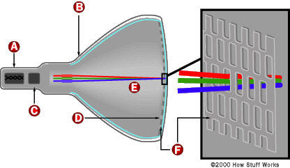

--------------------------------------------------------------------------------
11.1) No color - black and white picture
This means absolutely no color - equivalent to a black and white picture.
Not even a hint of color.
First, confirm that the source is actually in color - try another channel
or input device.
Next, check the settings of the color control - it may have accidentally
been turned down. If your TV has some kind of automatic picture mode,
try turning if off and adjusting the color control. Try adjusting fine
tuning if you have such a control and the problem is with a broadcast
or cable transmission.
At this point with a confirmed color signal source, there is a problem
with the chroma circuitry.
Note that to the average person, the obvious question becomes: is my color
picture tube bad? The answer is a definitive NO. It is virtually impossible
for a defective CRT to cause a total loss of color. A defective CRT can
cause a lack of a primary color - R, G, or, B or a short between two colors
which will mess up the color but is not likely to result in a black and white
picture.
Some possibilities in no particular order:
1. Weak signal or defect in tuner/IF causing loss of signal strength.
2. Coler killer set too high (internal control) if it has one.
3. Defective part around the chroma chip/circuit. Faulty color
oscillator.
4. Bad connections in area of chroma chip/circuit.
5. Defective chroma chip (don't suspect this first just because it
is probably very expensive).
A service manual or Sams', DMM, & scope will help greatly in attempting to
troubleshoot this unless it is an obvious bad connection. Try prodding
the main board around the chroma chip with an insulated tool to see if
you can make the color come and go.
I had one set where a $.02 resistor decided to open up causing just this
problem - perfect BW picture, no color. Another had a coil with a broken wire.
--------------------------------------------------------------------------------
11.2) Saturated color but almost no brightness
This means you have lost the luminance input to the chroma decoder or final
video chip. A failure of the brightness limiter may result in similar
symptoms.
A few common causes are:
* Check the service switch (if any). Its contacts may be dirty and moving it
back and forth a few times or using contact cleaner may be all that is
needed.
* Check for open high value resistors around the chroma decoder IC.
* Check for open high value resistors in the brightness limiter circuit.
With a scope and schematic (or even just a pinout for the chip), you should be
able to trace the luminance signal to see where it is getting lost.
This is also *not* a picture tube problme :-).
--------------------------------------------------------------------------------
11.3) Brightness control has no effect
The following assumes that the picture is fine but the brightness is
fixed - probably at too high a level. However, there could be several
interrelated problems if a common supply voltage were missing, for example.
If it is a knob, then it should be varying the control grid (G1) voltages
relative to the cathodes (K) of the CRT. This is not likely to be a very
complex circuit. If you do not have a schematic, I would start by tracing
from the control, check continuity and solder connections. Check the
control itself for proper operation with an ohmmeter. A power supply going
to one side of the control (negative probably) may be missing. Tbe control
grid voltage will end up on the little board on the neck of the CRT - check
there as well for bad solder connections or open resistors.
If brightness is a digital control, then you will need a schematic unless
there is an obvious bad connection.
--------------------------------------------------------------------------------
11.4) One color is too weak or too strong
If the problem is slight and/or has gradually gotten worse, this may just
require an adjustment of the color brightness/background/bias and/or color
gain/drive controls inside the TV. See the section: "Color balance adjustment".
Note that if it is possible to obtain a good black and white picture with the
user color control set to its minimum, then this is not likely a problem with
one of the primary color channels (red, green, or blue) but with the chroma
decoding circuitry. Or, perhaps, you are just watching MTV!
Even if it appears as though there is an excess, this may actually be a
reduction in one of the primary colors. For example, a magenta tinge is
represents a reduction in the strength of the green signal.
* Too high an intensity for one of the color channels will result in a tint of
one of the primaries: red, green or blue.
* Too low an intensity for one of the color channels will result in a tint of
the complement of one of the primaries: yellow, cyan, or magenta.
* Problems mainly in the shadows or dark areas of the picture usually represent
a fault with brightness/bias/background.
* Problems mainly in the highlights or bright areas of the picture usually
represent a fault with the gain/drive.
A color that that is now suddenly brighter or darker than normal resulting in
incorrect color balance or a tint in the background could be due to a number
of causes:
* Bad connections or bad component in video amplifier or on CRT neck board for
that color.
* Fault in chroma decoder.
* Weak gun in CRT (reduced color).
--------------------------------------------------------------------------------
11.5) Psychodelic color
The means colors that are not normal and that adjustment of the user
controls is not able to correct it so that all colors of the picture
are properly displayed at the same time. For example, you are unable
to get any yellows or blues in scenes that should have these colors..
Make sure the user color and tint controls have not been accidentally
turned while cleaning or purposedly misadjusted by small (or large) kids.
Perform the user setup described in the section: "User picture adjustment".
Confirm that the source is not a weird color video - try another
channel or a tape.
Verify that this is not a missing color problem - one of the primary R, G,
or B, has disappeared. If so, refer to the section: "Intermittent or missing colors".
Once these have been eliminated, you are left with the
following possibilities:
1. Defective part around the chroma chip/circuit. Misadjusted color
oscillator.
2. Bad connections or short circuit in area of chroma chip/circuit.
3. Defective chroma chip (don't suspect this first just because it
is probably very expensive).
4. Bad degauss circuit resulting in lack of degauss or abrupt termination
of degauss current rather than smooth tail off. The CRT is not being
properly demagnetized and color purity is totally messed up.
5. Bad CRT - the shadow mask has been damaged and it is impossible to
properly adjust purity across the screen.
A service manual or Sams', DMM, & scope will help greatly in attempting to
troubleshoot this unless it is an obvious bad connection. For (1)-(3),
try prodding the main board around the chroma chip with an insulated tool
to see if you can restore normal color. For (4) try manually degaussing
(see the section: "Degaussing (demagnetizing) a CRT". If this clears up
the colors until at least when it is power cycled, then a degauss problem
is likely.
Something as simple as a bad resistor or inductor can be the cause - don't
immediately suspect the most expensive and difficult to replace part.
--------------------------------------------------------------------------------
11.6) No picture/dark picture/erratic picture
Remove the picture tube socket (carefully!) and clean the pins with fine
sandpaper and use contact cleaner on the socket. This source of bad
connections can result in a variety of erratic symptoms.
--------------------------------------------------------------------------------
11.7) TV and Monitor Manufacturing Quality and Cold Solder Joints
Any intermittent problems with monitors that cause random sudden changes in
the picture brightness, color, size, or position are often a result of
bad connections.
Bad solder joints are very common in TVs and monitors due both to poor quality
manufacturing as well as to deterioration of the solder bond after numerous
thermal cycles and components running at high temperature. Without knowing
anything about the circuitry, it is usually possible to cure these problems
by locating all bad solder connections and cleaning and reseating internal
connectors. The term 'cold solder joint' strictly refers to a solder
connection that was either not heated enough during manufacturing, was
cooled too quickly, or where part pins were moved before the solder had
a chance to solidify. A similar situation can develop over time with
thermal cycling where parts are not properly fastened and are essentially
being held in by the solder alone. Both situations are most common with
the pins of large components like transformers, power transistors and
power resistors, and large connectors. The pins of the components have
a large thermal mass and may not get hot enough during manufacturing. Also,
they are relatively massive and may flex the connection due to vibration
or thermal expansion and contraction.
To locate cold solder joints, use a strong light and magnifier and examine
the pins of large components for hairline cracks in the solder around the
pin. Gently wiggle the component if possible (with the power off). Any
detectable movement at the joint indicates a problem. With the power on,
gently prod the circuit board and suspect components with an insulated
tool to see if the problem can be effected.
When in doubt, resolder any suspicious connections. Some monitors may
use double sided circuit boards which do not have plated through holes.
In these cases, solder both top and bottom to be sure that the connections
are solid. Use a large enough soldering iron to assure that your solder
connection is solid. Put a bit of new solder with flux on every connection
you touch up even if there was plenty of solder there before.
--------------------------------------------------------------------------------
11.8) Why can't TV manufacturers learn to solder properly?
I can think of several potential reasons - all solvable but at higher
manufacturing cost.
1. Mass of large component leads (like shields) does not get adequately
heated during manufacture leading to latent cold solder joints. While
they may look ok, the solder never actually 'wetted' the heavy pins
and therefore did not form a good mechanical or electrical bond.
2. Thermal cycles and differential thermal coefficients of circuit boards,
traces, and solder. While it is not easy to do anything about the
material properties, using plated through-holes or a similar mechanical
via would greatly increase the surface area of the joint and prevent
the formation of cracks.
3. Vibration. This is also directly related to the single sided circuit
boards without plated through-holes to strengthen the joints.
4. Lack of adquate mechanical support (single sided circuit boards without
plated through-holes (vias).
I believe that the single most significantimprovement would come about
by using plated trhough-holes but this would add to the cost and apparently
the consumer is not willing to pay more for better quality and reliability!
Some designs have used rivlets - mechanical vias instead of plated ones.
While this is good in principle, the execution has often been flawed where
cold solder joints resulted between the rivlets and the circuit board traces
due to lack of adequate process control.
The Sony and RCA/GE tuner shield problem is interesting because this
could have been solved years ago at essentially no additional cost as
other manufacturers - and their own repair procedures - have proven.
--------------------------------------------------------------------------------
11.9) Intermittent or missing colors
This is a catch-all for some of the most common TV and monitor problems.
* If gently whacking the set can make the color(s) come and go suddenly, then
bad connections are probable. The most likely place for these are solder
pads on the little circuit board on the neck of the CRT or even dirty CRT
socket pins that are not making solid contact. Try prodding the CRT neck
board with an insulated stick to see if you can affect the colors.
Although not impossible, this is not likely to be a CRT problem.
* If the color fades in and out with a delay of about 10-15 seconds, it is
probably intermittent power to the CRT filament for that color and probably
means a bad CRT since the three filaments are wired in parallel inside the
CRT. One of the internal connections has come loose.
Look in the neck of the CRT to make sure all three filaments are glowing
orange. If one is out or goes on and off, toss the set. Replacing the CRT
is probably not worth it. However, if they all go on and off together (all
colors would be fading in and out though perhaps not quite in unison), then
bad connections for the CRT filaments on the CRT neck board are indicated.
To narrow down the problem:
* Locate the output for the bad color on the video driver board on the
neck of the CRT. This will probably read a significantly higher
voltage than the corresponding pins for the good colors. A circuit
problem is likely - probably on this board.
* Test components on this board for the good and bad color channels. A
shorted transistor or open resistor can kill one channel. Swap parts
between good and bad colors to confirm.
* Gently pull the CRT neck board off of the CRT and replace it. This will
tend to clean the contacts.
* Connect an output of the video/chroma circuit/chip that is working (i.e.,
a color that appears on the screen) to *all* three color drivers on the CRT
neck board.
- If you now get a more-or-less black and white picture (there may be a
moderate color tint as the relative intensities of R,G,B may not be
balanced), the problem is likely with the chroma decoder or its support
circuitry.
Note: the picture will be the intensity of only one color channel so it
will not be quite *normal* in any case.
- If you still have missing or messed up colors, the problem is on the CRT
neck board or with the CRT.
Most of the causes of intermittent colors boil down to bad connections
of one form or another. For totally dead colors - not intermittent - bad
components are also a possibility.
* Printed circuit board on the CRT neck. This is a common location for
cold solder joints. Check with a bright light and magnifying glass
for hairline cracks around the pins of larger parts. Prod and tap with
an insulated tool to see if the problem is effected. Resolder if necessary.
* Cold solder joints elsewhere in TV or monitor usually around the pins of
large parts such as transformers, power transistors and resistors, and
internal connectors.
* Internal connectors (including CRT socket) that need to be cleaned and
reseated. Remove, clean with contact cleaner, burnish, and replace.
--------------------------------------------------------------------------------
11.10) Some commentary on monitor and TV whacking
Anytime that intermittent symptoms are experienced, I recommend gently
whacking the patient to determine if mechanical shock or vibration affects
the behavior. Here are a couple of responses to this suggestion.
(The following is from Marc Gelfond (71363.1700@CompuServe.COM)):
I just love the bit about "whacking it". It brings to mind an
episode from the old Andy Griffith show, where a new fangled piece
of electronics gear, was broght into Emmets repair shop. After
many long hours of fruitless troubleshooting, out of frustration
Emmet gave the thing a whack, and sure enough it fixed the problem.
As we say in the Telephony business, it "CCWT" or Came Clear While Testing.
Another saying is that it "CCBFM" Came Clear By F------ Magic!!
(To which Gavin Adams (gaa@hopi.com) comments):
In the video industry we had a saying concerning malfunctioning gear:
"If it's broke, hit it with a hammer"
"If that doesn't fix it, paint it and sell it"
My DEC 16" monitor is case in point. Evey once in a while it would lose sync,
and smacking it would bring it back (sometimes a few smacks). Recently it
gave up the ghost completely, and after the local DEC office gave me a quote
of $900 to fix it (Bermuda), I ordered a new Viewsonic 17" for the same price.
I ripped the guts out of the DEC beast, painted it with a marble finish, put
plants in it, and sold it! :>
--------------------------------------------------------------------------------
11.11) Retrace lines in picture
During the time the electron beam is returning from right to left at the end
of a line and bottom to top (over the course of multiple lines), it is supposed
to be result in no visible light on the screen. However, a number of faults
can result in visible retrace lines.
The appearance will likely be a general reduction in contrast from the visible
horizontal retrace on every scan line and two dozen or so diagonal lines lines
(lower left to upper right) resulting from the vertical retrace.
The retrace lines may be either white or gray (possibly with a slight color
tint due to unequal settings of the color adjustments) or a primary color -
red, green, or blue. Anything in between is also possible but less likely.
--------------------------------------------------------------------------------
11.12) White/gray retrace lines
Where all colors are involved - the lines are essentially white or gray (or
with a slight tint due to slight unequal settings of the color adjustments),
look for something common like an incorrectly adjusted screen (G2) or master
brightness/background/bias control or a problem in one of these circuits, a
defective power supply or a problem in the blanking circuitry:
* Screen (G2) or master brightness/background/bias control - mark setting and
then see if a slight adjustment removes the retrace lines. See the chapter:
"TV Adjustments". Of course, if this happened suddenly, the problem is not
due to a misadjusted control though a dirty pot is possible - turn it back
and forth - this might clean it and restore normal operation.
* Power supply or connection to CRT neck board - insufficient voltage will
result in the CRT never totally blanking. Check (usually scan derived)
power supply components (from flyback).
* General power supply - check B+ for correct value and ripple. A main power
supply fault might result in these symptoms (and usually many others).
* Blanking circuit - this may be a part of the video/chroma chip or separate.
Check waveforms to determine if the blanking pulses are making it to the
video output.
--------------------------------------------------------------------------------
11.13) Red, green, or blue retrace lines
Where only one color is showing, suspect an incorrectly adjusted individual
background/bias control or bad part on the CRT neck board for that color.
* Individual brightness/background/bias control(s) - mark setting of pot for
the problem color and then see if a slight adjustment removes the retrace
lines. See the chapter: "TV Adjustments". Of course, if this happened
suddenly, the problem is not due to a misadjusted control though a dirty
pot is possible - turn it back and forth - this might clean it and restore
normal operation.
* Component or connection on CRT neck board - insufficient voltage to or
incorrect biasing of the video driver for this color can result in the
CRT never totally blanking. Compare voltages and signals, and swap
components between good and bad channels to confirm.
* Blanking circuit - this may be a part of the video/chroma chip or separate.
Check and compare waveforms of good and bad colors to determine if the
blanking pulses are making it to the video output.
There is a slight possibility that a bad CRT may result in visible retrace
lines. To eliminate this possibility:
* Disconnect the filament - all evidence of a picture, raster, and retrace
lines should disappear once the filaments/cathodes have cooled (15 seconds
or so. If there are still visible retrace lines, the CRT is suffering
from cold or field emission from someplace (may not even be the cathode).
* Turn down the screen (G2) control on the flyback (usually). If one color
remains no matter how you set the control, again there is some kind of
weird emission from the CRT. However, if white/gray retrace lines remain,
the problem may be in the screen supply.
See the section: "Bad CRT causing retrace lines".
--------------------------------------------------------------------------------
11.14) Bad CRT causing retrace lines
(From: Jeroen H. Stessen (Jeroen.Stessen@ehv.ce.philips.com)).
The TV which I bought last started developing retrace lines after a month or
so of use. I took it back to the lab for warranty (special deal) and had it
examined by the real experts. They found that even with the filament supply
disconnected and VG2 at 0V the screen would still light up. They could even
see that the electrons weren't even coming from the cathode. That was with
only the picture tube in a test rig. So in this case the obvious conclusion
had to be that the tube was bad, and it was replaced (32" 16:9 SF, very $$).
It had something to do with processing problems during manufacturing of the
electron guns.
So even if this was a rare case, it *can* happen that retrace lines are due
to a bad picture tube. It's more usual to suspect the VG2 (screen voltage)
or a defect somewhere in the RGB video path.
--------------------------------------------------------------------------------
11.15) Red, green, or blue full on - fog over picture
This could be a heater-cathode (H-K) short in the CRT or a failure
of a component in the chroma circuits or video output (driver board).
Don't panic - heater-cathode shorts in CRTs can often be worked around.
Note: before proceeding, it is a good idea to make sure that the screen is
degaussed - else you could be attempting to track down problems with the wrong
color!
Some simple tests can confirm or rule out other possibilities.
* Compare the voltages for the video drive signals to the CRT on the little
board on the neck of the CRT with the CRT both connected and unplugged.
A schematic will help greatly in locating these signals.
- If there is a significant difference especially on the bad color, then the
CRT is a likely candidate. Try tapping the neck of the CRT GENTLY (with
it plugged in and while viewing a picture) to see if it is an intermittent
problem.
- If there is no significant difference, you may have a bad driver or a
problem in the chroma circuits.
* Look for bad connection/cold solder joints, probably on the little
board on the neck of the CRT. Use an insulated stick to gently prod
the board and its components in an effort to induce/cure the problem.
Look carefully for hairline cracks around the component leads.
* You can swap components between two colors and/or test with an ohmmeter
on that driver board to determine what is bad. The nice thing about
color monitors and TVs is that there three copies of each of these
components. Swapping and/or comparisons between these is an excellent
diagnostic technique.
* Another simple test: Disconnect the cathode for the full-on color from its
drive. If it is still full-on, there is probably an H-K short in the CRT
since the only way to get each color on the screen is via the cathode
connection to the CRT neck board. If it is removed and there is still that
color, the current must be taking another path inside the CRT.
* Alternatively, interchange the outputs of the bad color with a good one
by jumpering on the video driver board (on the CRT neck). If the bad
color changes, then the problem is in the circuitry and not the CRT.
Here is the procedure in more detail (example for red full on):
(From: J. K. Emerine (jkemerine@aol.com)).
To identify if the fault is in the crt or a control problem try this (WITH
SET OFF):
On the CRT board, lift the output end of the green cathode final resistor.
Do the same with the offending red cathode's resistor. Use short insulated
jumpers to 'swap' drive signals - drive the red cathode with the green
drive and the green cathode with red drive. (Note that if this problem
only occurs after a warmup period, color at turn on will be - well - wierd,
but it is just a test.)
- If the symptom returns = 'goes red' the CRT is shorting. (See the section:
"Providing isolation for a CRT H-K short". --- sam)
- If instead the symptom becomes 'goes green' then the red drive leg has
the fault and the CRT is probably good. (In this case, there may be bad
connections or a bad component on the CRT drive board or further back
in the chroma circuitry. --- sam)
--------------------------------------------------------------------------------
11.16) Shorts in a CRT
Occasionally, small conductive flakes or whiskers present since the day of
manufacture manage to make their way into a location where they short out
adjacent elements in the CRT electron guns. Symptoms may be intermittent or
only show up when the TV or monitor is cold or warm or in-between. Some
possible locations are listed below:
* Heater to cathode (H-K). The cathode for the affected gun will be pulled
to the heater (filament) bias voltage - most often 0 V (signal ground). In
this case, one color will be full on with retrace lines. Where the heater
is biased at some other voltage, other symptoms are possible like reduced
brightness and/or contrast for that color. This is probably the most
common location for a short to occur.
* Cathode to control grid (K-G1). Since the G1 electrodes for all the guns
are connected together, this will affect not only the color of the guilty
cathode but the others as well. The result may be a very bright overloaded
*negative* picture with little, none, or messed up colors.
* Control grid to screen (G1-G2). Depending on circuitry can result in any
degree of washed out or dark picture.
* Screen to focus (G2-F). Screen (G2) and focus voltage will be the same and
the controls on the flyback will interact. Result will be a fuzzy white
raster with retrace lines and little or very low contrast picture. Symptoms
will be similar to those of a flyback with breakdown in the focus/screen
divider network.
* Focus to high voltage (F-HV). High voltage will be pulled down - probably
arcing at the focus spark gaps/other protective devices. Line fuse and/or
HOT may blow.
* Other locations between electron gun elements as feed wires.
Replacing the CRT may be required but there are a variety of 'techniques' that
can often be used to salvage a TV that would otherwise end up in the dump
since replacing a CRT is rarely cost effective:
1. Isolation - this will usually work for H-K shorts as long as only one gun
is involved.
2. Blowing out the short with a capacitor - depending on what is causing the
short, this may be successful but will require some experimentation.
3. Placing the CRT (TV or monitor) face down on a soft blanket and *gently*
tapping the neck to dislodge the contamination. Depending on the location
of the short, one side or the other might be better as well. Sometimes,
this can be done in-place while watching the picture.
A combination of (2) and (3) may be required for intermittent shorts which
don't appear until under power. See the sections below for additional
details. However, for shorts involving the focus and high voltage elements,
even a sharp edge can result in arcing even if there is no actual short.
There is no remedy for these types of faults.
--------------------------------------------------------------------------------
11.17) Providing isolation for a CRT H-K short
This procedure will substitute a winding of your own for the one that is
built in to the flyback to isolate the shorted filament from the ground
or voltage reference. Note that if you have a schematic and can determine
where to disconnect the ground or voltage reference connection to the
filament winding, try this instead.
The flyback is the thing with the fat red wire coming out of it (and perhaps
a couple of others going to the CRT board or it is near this component
if your set has a separate tripler) and may have a couple of controls for
focus and screen. It should have some exposed parts with a ferrite core
about 1/2-3/4" diameter.
The filament of the CRT is the internal heater for each gun - it is what
glows orange when the set is on. What has happened is that a part of the
fine wire of the bad color's filament (assuming this is indeed your problem)
has shorted to the cathode - the part that actually emits the electrons.
Normally, the heater circuit is grounded or tied to a reference voltage
so when it shorts to the cathode, the cathode voltage level is pulled to
ground or this reference.
You will need some well insulated wire, fairly thick (say #18-22). Find a
spot on the flyback where you can stick this around the core. Wrap two
turns around the core and solder to the CRT filament pins after cutting the
connections to the original filament source (scribe the traces on the board
to break them). Make sure you do not accidentally disconnect anything else.
This winding should cause the filaments to glow about the same brightness as
before but now isolated from ground. If they are too dim, put another turn
on the flyback to boost the voltage as this will result in low emission,
blooming, and possible damage to the cathodes after awhile. (Don't go
overboard as you may blow the filament totally if you put too many turns on
the core - you then toss the TV.)
Route the wires so that there is no chance of them getting near the high
voltage or any sharp metal edges etc. Your picture quality may be a tad
lower than it was before because of the added stray capacitance of the
filament wiring being attached to the the (formerly bad) video signal, but
hey, something is better than nothing.
If you are not inclined to build your own isolation transformers, kits are
available:
(From: Alan Harriman (capstv@sprynet.com)).
A company called KDTV/IWE carries kits (core, wire and tie) for $3.30 each.
It takes all of two minutes to wind.
Check out: http://www.seidata.com/~kdtv.
BTW, I am just a satisfied customer.
--------------------------------------------------------------------------------
11.18) Rescuing a shorted CRT
If the short is filament-cathode (H-K), you don't want to use the following
approach since you may blow out the filament in the process. If this is the
case, you may be able to float the filament and live with the short (see the
section on: "Red, green, or blue full on - fog over picture".
Shorts in the CRT that are between directly accessible electrodes can
be dealt with in a more direct way than for H-K shorts. At this point
you have nothing to loose. A shorted CRT is not real useful.
If the short is between two directly accessible electrodes like cathode-grid,
then as a last resort, you might try zapping it with a charged capacitor.
Start with a relatively small capacitor - say a few uF at a couple hundred
volts. Check to see if the short is blown after each zap - few may be needed.
Increase the capacitance if you fell lucky but have had little success with
the small capacitor.
If the fault is intermittent, you will, of course, need to catch the CRT
with the socket disconnected and the short still present. Try some gentle
tapping if necessary. If you do this with the charged capacitor across
the suspect electrode, you **will** know when the short occurs!
--------------------------------------------------------------------------------
11.19) Picture tube replacement
It is possible to replace the picture tube. However, this is likely to
be both expensive and possibly time consuming with respect to adjustments
like purity and convergence. When replacing:
* Discharge both the old and new tubes before you start to be sure you won't
have any unpleasant surprises.
* Take extreme care when handling - at the very least, a slip can result in a
broken neck and a bad and expensive day.
"The 25VCXP22 picture tube of my RCA Accutouch XL-100 CCU-942 TV start fading.
Its 100% transistorized, everything still works perfectly after about 20
years service. but:
* Can I still buy new RCA 25VCXP22 picture tube? What is the approximate cost?
* Any equivalent tube for direct replacement? Cost?
* If no replacement picture tube is available, what is other option?"
(From: Chris Jardine (cjardine@wctc.net)).
What you have here is genericly referred to as the 25V as opposed to the 25A
picture tube. While there are minor differences with respect to the letters
after the V for the most part they are interchangeable. When I worked my way
through engineering college I worked at a TV repair shop and my job was mostly
changing picture tubes. Yeah, we did enough of them to keep a tech busy 4 to 5
hours a day changing them and I got pretty good and could change, color
balance, convergence, etc. the tube in about 45 minutes. We for the most part
used 3 major tubes, 1) 25A, 2) 25V, and 3) 21FJ (a little nostalgic for those
who remember this one). This was back when your TV would have been fairly new
(1981 to 82). These are available from many different sources - RCA, Channel
Master, Wisconsin Tube, etc. The price would vary depending on the quality of
the tube. I remember that we could get a 25A for about $35 at the time due to
our volume - one truck per month. The most expensive I've seen them has been
just over $200. This is quite a range and there are now many other types of
tubes including in-line, trinitron, etc.
I hope this helps and thanks for the trip down memory lane!
(From: Chris Jardine (cjardine@wctc.net)).
The important thing here is that the tube begins with 25V. If it does it should
work in your set. The only thing you have to know is whether the tube has
'ears' attached permanently. The 25V comes both with and without these mounting
ears permanently attached. I know that you can still get one of these from any
of a number of suppliers. I know that Channel Master and RCA (Thompson,
whatever!) still make them available as well as any of a number of local CRT
rebuilders.
--------------------------------------------------------------------------------
11.20) Dark picture
A TV or monitor with a picture that is too dark may have a fault or the CRT may
just be near the end of its useful life.
First, confirm that your video source - computer, camera, etc. - is producing
a proper signal.
Is the brightness at all erratic? Does whacking the monitor have any effect?
If so, then you may have bad connections on the CRT driver card or elsewhere.
If the brightness tends to fade in and out over a 10 to 20 second period,
a bad filament connection is likely. Check for the normal orange glow of
the filaments in the neck of the CRT. There should be 3 orange glows. If
they are excessively reddish, very dim, or fade in and out, you have located
a problem. See the section: "Picture fades in and out".
Common causes of brightness problems:
0. Dirty CRT faceplate or safety glass. Don't laugh. It sounds obvious, but
have you tried cleaning the screen with suitable screen cleaner? It is
amazing how dirty screens can get after a few years - especially around
smokers!
Wipe gently with a slightly dampened cloth - not soaking or you may end
up with real problems when the water drips down inside and hits the
electronics! On TVs with a separate protective faceplate, clean both
the front and rear surfaces of this plate as well as the CRT itself.
1. Old CRT. The brightness of the CRT deteriorates with on-time. It does not
matter much how bright your run your TV. An indication of a weak CRT would
be that turning up the SCREEN (G2) or master brightness control only results
in a not terribly bright gray raster before the retrace lines show up.
There may be indications of poor focus and silvery highlights as well. A
CRT brightener may help. See the section: "Brightening an old CRT".
2. Bad component in filament circuit or bad connection reducing filament
voltage. This should be easy to check - there are only a few parts
involved. If it is erratic, bad connections are likely.
3. Brightness control faulty - bad pot, bad connections, or problem with its
power supply. Depending on specific problem, control may or may not have
any effect. If digitally adjusted, there could be a problem with the
logic or control chip. If the button or menu item has no effect at all,
then a logic or control problem is likely.
4. Improperly set SCREEN (G2) voltage (usually on flyback) or faulty divider
network. See the section: "Adjustment of the internal SCREEN and color controls".
5. Improperly set video bias (background) levels or fault in video drive
circuitry. See the sections starting with: "Optimal procedure for setting brightness/background and screen adjustments".
6. Fault in video amplifiers. With all three color affected equally, this
would most likely be a power supply problem. A video amplifier problem
is likely if turning up the SCREEN (G2) or master brightenss control
results in a very bright raster before the retrace lines appear. Cheack
signals out of the video/chroma(IC.
7. Fault in beam or brightness limiter. Many TVs and monitors measure the
beam current (possibly indirectly) and limit the maximum to a safe value.
The purpose of this may be to protect the CRT phosphors, and/or to assure
that the power supply does not go out of regulation, and/or to limit X-ray
emission. If this circuit screws up, a dark picture may result. Checking
the signals and voltages at the CRT socket should determine if this is the
problem.
8. High voltage is low. However, this would likely result in other symptoms
as well with focus, size, and geometry.
--------------------------------------------------------------------------------
11.21) Brightening an old CRT
If performing adjustments of the internal background and/or screen controls
still results in a dark picture even after a long warmup period, the CRT
may simply be near the end of its useful life. In the old days of TVs
with short lived CRTs, the CRT brightener was a common item (sold in every
corner drugstore, it seemed!).
You can try a similar approach. Caution: this may shorten the life of
the CRT - possibly quite dramatically (like it will blow in a couple of
seconds or minutes). However, if the monitor or TV is otherwise destined
for the scrap heap, it is worth a try.
The approach is simple: you are going to increase the voltage to the
filaments of the electron guns making them run hotter. Hopefully, just
hotter enough to increase the brightness without blowing them out.
Voltage for the CRT filament is usually obtained from a couple of turns
on the flyback transformer. It is usually easy to add an extra turn or two
which will increase the voltage and thus the current making the filaments
run hotter. This will also shorten the CRT life - perhaps rather drastically.
However, if the TV or monitor was headed for the dumpster anyhow, you have
nothing to lose.
--------------------------------------------------------------------------------
11.22) Picture tube brightener
(From: Kevin Carney (carneyke@mhv.net)).
Try a CRT brightener from MCM Electronics about $20. It boosts the
filament voltage a volt or two. I have used them before and they help.
You can also try running a power supply on the filament with the
monitor OFF. Set the supply at the filament voltage and slowly bring
the voltage up. If the filament is 6.3 volt bring it up gradually to
10 -12 volts for about a half hour. This will brighten it up some.
Be careful because too much voltage can open the filament !
Before doing this did you check the screen voltage setting and the
RGB settings for drive and background ?
There are also commercial CRT rejuvenators that supposedly zap the
cathodes of the electron guns. A TV repair shop may be able to
provide this service, though it is, at best, a short term fix.
--------------------------------------------------------------------------------
11.23) More drastic measures to brighten CRT
(From: LEE (leep@mailhub.scf.lmsc.lockheed.com)).
As a start, I crank the brightness control all of the way up. I then turn the
color control all of the way up. I let the set run with a bright screen for
around 15 min. This procedure cleans up the cathode surfaces so that they can
emit more electrons. Now turn the controls back to normal and see if any
improvement took place. If not, Wrap 2 or 3 turns of around 18 gauge insulated
wire around the flyback and add this extra power in series with existing
filament leads from flyback. You can experiment with the number of turns etc.
to get brighter filaments. do not run the filaments white - just a brightened
yellow. This will probably turn out to be around 8-9v in most cases. I had to
do this on two different Sanyo replacement flybacks as they had low filament
voltage from the factory. (flakey replacement parts). I`ve been running one of
these Sanyos for around 4 years now with a nice bright picture (13")
--------------------------------------------------------------------------------
11.24) Left portion of screen is dark or faded
"I've got an old TV where the left 1/3 of the screen is 'faded'. It is
especially noticable when a dark picture is showing (like a night time
scene)."
This is normally caused by a bad filter capacitor on the power supply line
(typically 200 V) that feeds the RGB output transistors. It is usually a scan
derived voltage off of the flyback. Look for an electrolytic capacitor of
around 4.7 to 10 uF, 160 to 250 V fed from a rectifier diode on this supply.
--------------------------------------------------------------------------------
11.25) Color balance changes across screen from left to right
The characteristics are that a solid white screen will tend to be blue tinted
on one side and red tinted on the other. This is usually a subtle effect and
may be unavoidable with some designs.
There are several possibilities:
1. Purity - this means the beams are landing on the wrong phosphor dots.
This is what would be affected by moving from one location to another
or even rotating the TV on its base without degaussing. If the problem
just appeared, degaussing may be needed.
What do you have near the TV or monitor? Loudspeakers or other devices
which generate magnetic fields can easily cause all sorts of color purity
problems. Relocate the offending device(s) or the TV or monitor and then
degauss it.
See the section: "Degaussing (demagnetizing) a CRT".
If the problem still persists, purity adjustment may be needed. However,
this isn't likely to have changed so look for other causes before tackling
these adjustments.
2. Unequal electron gun to shadowmask/screen distance - the electron beams for
the red and blue video travel slightly different distances on the left and
right sides of the screen so their intensity (due to focus not being optimal
and other factors) in each case may differ slightly affecting color balance.
3. Doming - This would only happen in very bright areas and causes the
shadow mask to expand and distort. (Doming should not be a problem with
Trinitron CRTs which use tensioned wires in their aperture grill.) This
would also not really affect left-right color balance in particular.
I don't really know how much of a problem (2) is in practice or whether some
manufacturers compensate for it.
--------------------------------------------------------------------------------
11.26) Bleeding highlights
On very bright areas of the picture, one or more colors may bleed to
the right resulting in a trail of those colors. The difference between
this problem and the section: "Trailing lines in one or more colors" is
that in this case, only highlights are affected.
One cause of this is that the color gain, contrast, or intensity controls
(whatever they are called on your set) are set too high. See the section
on: "Color balance adjustment". Check the settings of any brightness limiter
controls as well.
--------------------------------------------------------------------------------
11.27) Trailing lines in one or more colors
Assuming this is not a form of ghosting resulting from poor reception
conditions, then it could be any of the following:
* Poor decoupling in the power supplies for the video drive circuits - probably
on the CRT neck board. Check for bad (low uF or high ESR) filter capacitors
(electrolytic mostly) on this board or the power supplies feeding it.
* Insufficient CRT filament voltage. This could be a result of bad connections
or a bad component in the filament power supply (probably from the flyback).
Check to see if the filaments are glowing bright orange and check the voltage
if possible (though this can be tricky since it is often fed from a winding
on the flyback and is a pulse waveform, not DC or a sinusoid. The service
manual (or Sams' Photofact) will probably have info and waveforms.
* Bad CRT (more likely if only one color is affected). A weak electron gun can
result in this behavior. Swap it with one that work properly. If the same
color is still bad, that CRT gun is weak. The CRT will need rejuvenation or
need to be replaced (more likely, the entire TV will be tossed into the
dumpster).
--------------------------------------------------------------------------------
11.28) Brightness changes from left-to-right across screen
Slight variations in brightness across the face of the CRT are not unusual.
In fact, if you used a photometer to actually measure the brightness, you
might be amazed at the actual variance even with the best TV - you just
don't notice it. However, a major variation - usually a decay from left to
right but could be the other way indicate a component failure. Of course,
make sure the face of the screen is clean!
* A fault in the power supplies to the video amplifier and/or video output
circuits. Most likely, an electrolytic capacitor has dried up and is not
adequately filtering the power derived from the flyback which then has
ripple at the horizontal scan rate and thus locked to the screen. The
voltage decays from left-to-right between horizontal flyback pulses.
The most likely location for these capacitors is in the vicinity of the
flyback transformer on the mainboard or on the CRT neck board. Check the
capacitors with capacitor tester or ESR meter and/or take a look at the
power right at the video amplifier and video output drivers.
* Horizontal linearity is bad - this may actually be a horizontal geometry
problem and not a brightness problem.
See if objects on left side of the screen are stretched compared to those on
the right (or vice-versa). If they are, the problem is in the horizontal
deflection circuits - possibly a bad S correction capacitor or linearity
coil.
* Inoperative degauss circuit, TV moved or rotated without degaussing, or
magnetic field from some other device (like a permanent magnet) is affecting
CRT - slight amounts of magnetization may reduce brightness (by moving the
beams into the black space between phosphor dots) before affecting color
purity (where the beams land on the wrong phosphor dots).
Try deguassing manually. See the section: "Degaussing (demagnetizing) a CRT".
--------------------------------------------------------------------------------
11.29) Picture fades in and out
If the picture faded away on the order of 10-20 seconds (and if it comes
back, also comes up to full brightness in same time frame - possibly
with the persuasion of some careful whacking) AND with NO other
significant changes such as size, focus, etc., then take a look in the back of
the tube for the filament to be lit - the orange glow near the CRT socket. If
there is none, then you probably have a bad solder connection on the circuit
board on the neck of the CRT. Look for fine cracks around pins on that board.
Try prodding it with an insulating stick to see if the picture comes back.
Resolder if necessary. It is probably not a bad CRT as the filaments
are usually wired in parallel and all would not go bad at the same time.
However, if only a single color fades in and out, then a bad connection
inside the CRT is a distinct possibility - look for only one of the
filament's glow to be coming and going. This is probably not worth fixing.
If the picture faded away with other symptoms, then there is probably
a fault in the video amplifier/output one of its power supplies -
still probably a loose connection if you are able to get it back by
whacking.
--------------------------------------------------------------------------------
11.30) Occasional brightness flashes
These may last only a fraction of a scan line or much much longer.
This could mean an intermittent fault in a variety of places including
the video circuitry and SCREEN power supply:
* Brightness circuitry - SCREEN, master background or its power supply.
Could be in or around flyback or focus/screen divider. Could perhaps
be in the CRT, but probably less likely.
* Video amp before or at chroma demodulator - since after this point, you would
most likely get colored flashes since only one of the RGB signals would
likely be effected.
If you get it from all sources, then tuner/IF is ruled out.
Suppose you just have no signal to a direct video input. What do you
get? If you still get flashes, it should be real easy to monitor either
the video outputs or SCREEN supply (with a HV divider on your scope) for
noise. Then trace back to power or noise source.
--------------------------------------------------------------------------------
11.31) Excessive brightness and/or washed out picture
There are a number of possibilities including incorrect screen (G2) or bias
(G1) voltages, or a problem in the video or blanking circuitry. Any of these
could be the result of bad connections as well. A short in the CRT can also
result in these symptoms.
* Excessive brightness/washed out picture is often an indication of a
problem with the screen (G2) supply to the CRT. May be a bad capacitor
or resistor divider often in the flyback transformer assembly or on
the board on the neck of the CRT.
* If the excessive brightness just developed over time, then a simple
adjustment of the screen or background brightness controls may keep
it (and you) happy for a long time.
When good, a typical value would be in the 200 to 600 VDC at the CRT. The
screen (it may also be called master brightness, bias, or background) control
should vary this voltage. However, it may be difficult to measure as the
resistors in the voltage divider network may be quite large - hundreds of M
ohms. If your unit has an external screen control (less likely these days)
and it has no effect, trace out the circuitry in the immediate vicinity and
check the resistors and potentiometer for opens, look for bad connections,
etc. If it is built into the flyback transformer and is sealed, the entire
flyback will need to be replaced unless the actual problem turns out to be a
bad connection or bad component external to the flyback.
* Where the brightness control has no effect, suspect a missing bias supply to
the G1 (control grid) electrodes of the CRT. This is usually derived from
the flyback with a simple rectifier/filter capacitor power supply. Parts
may have failed (though not likely the flyback itself). Adjusting the user
brightness control should vary this voltage over a typical range of 0 to -50
V with respect to signal ground.
* It could also be a problem with biasing of the video output transistors.
There may individual controls for background brightness on the little board
on the neck of the CRT. However, we are looking for a common problem since
all colors are wrong in the same way. This is likely to be a missing voltage
from a secondary supply from the flyback.
* A short between electrodes inside the CRT can result in brightness problems.
It may be possible to check this with an ohmmeter with the power off and the
CRT socket removed. Test between G1, G2, and F where all colors are
affected though a short between F and G2 will result in the focus control
changing brightness and vice-versa - a classic symptom.
However, in some cases, it only shows up when operating and one must deduce
the presense and location of the short from its affect on voltages and bias
levels.
See the section: "Rescuing a shorted CRT" and other related topics.
First, check for bad connections/cold solder joints by gently prodding
with an insulating stick. Check voltages and bias levels.
--------------------------------------------------------------------------------
11.32) Bad focus (fuzzy picture)
Focus voltage on the CRT is usually in the range of 2-8 KV DC and should
be controllable over a fairly wide range by the focus pot - usually located
on the flyback or a little panel in its vicinity:
* If adjusting the pot results in a position of acceptable focus, you may be
done. It is not unusual for the focus setting to drift a over time.
* If the setting is already as good as possible but not really good enough,
the CRT may be tired. Alternatively, the filament voltage may be too low.
Check for bad connections in the filament circuit.
* If the optimal setting is out of range of the focus pot, the problem is
likely leakage in the focus divider in the flyback or one of the components
on the CRT neck board.
Also see the sections: "Focus adjustment" and "Focus drifts with warmup".
The focus wire usually comes from the flyback or if the general area or from a
terminal on a voltage multiplier module in some cases. It is usually a wire
by itself going to the little board on the neck of the CRT.
If a sparkgap (a little 2 terminal device with a 1/8" gap in the middle)
is arcing with power on, then the resistive divider has shorted inside
the flyback, focus board, or HV multiplier - whatever you TV has - and
the this unit will need to be replaced. Ditto if the SCREEN control affects
focus and/or vice-versa.
Using a suitable high voltage meter (range at least 10 KVDC, 1000 M ohm or
greater input impedance), you should be able to measure it connected and
disconnected. The ground return will be the outside coating of the CRT which
may or may not be the same as the metal chassis parts. If the voltage is very
low (less than 2 KV) and the pot has little effect:
* When measured right off of the source disconnected from the CRT neck board,
then the problem is probably in the focus network in the flyback (or wherever
it originates). Sometimes these can be disassembled and cleaned or repaired
but usually requires replacement of the entire flyback or voltage multiplier.
Note: you may need to add a HV (10 KV) capacitor between the focus wire and
DAG ground to provide filtering so you get a DC level for your meter.
* When measured with the focus wire attached to the CRT neck board with the
CRT connected but reasonable with the CRT unplugged, there is probably a
short between the focus and another electrode inside the CRT. See the
section: "Rescuing a shorted CRT".
* When measured with the focus wire attached to the CRT neck board with the
CRT unplugged, there is likely a component on the CRT neck board that is
leaky or breaking down. Also, check for decayed (tan or brown) glue which
may turn leaky with age.
--------------------------------------------------------------------------------
11.33) Focus drift with warmup
This could be due to a problem with the focus voltage power supply, components
on the CRT neck board, or a tired worn CRT.
Focus is controlled by a voltage of 2-8 KV DC usually derived from the flyback
transformer and includes some resistors and capacitors. One of these could
be changing value as it warms up. (assuming nothing else changes significantly
as the unit warms up - e.g., the brightness does not decrease.)
Focus voltage is derived from a subset of the high voltage winding on the
flyback using a resistive voltage divider which includes the focus pot.
These are extremely high value resistors - 200 M ohm is common - and so
leakage of any kind can reduce or increase the focus voltage. All other
things being ok - i.e., the picture is otherwise fine - I would suspect this
type of failure rather than the CRT.
The connection to the CRT is usually a separate wire running from the flyback
or its neighborhood to the CRT neck board. Look for components in this
general area. Use cold spray or a heat gun to isolate the one that is
drifting. If you have access to a high voltage meter, you should be able
to see the voltage change as the TV or monitor warms up - and when you cool
the faulty part. If it is in the flyback, then sometimes the part with the
adjustments clips off and can be repaired or cleaned. Most often, you will
need to replace the flyback as a unit.
* If the optimal adjustment point of the focus control doesn't change that
much but the best focus is simply not as good as it should be, the CRT is
probably the problem. However, if the optimal point produces acceptable
focus but it changes (and possibly moves off of one end of the adjustment
knob range) as the unit warms up, the flyback or one of the components on
the CRT neck board are likely drifting.
* If you have a high voltage meter, you can measure the focus voltage to
determine if it is being changed by the focus pot and if it is in the
ball park (2-8 KV typical). Sometimes, the part of the flyback with the
focus pot can be snapped off and cleaned or parts replaced but usually you
need to replace the whole unit. There may a capacitor or two on the PCB on
the neck of the CRT that could have increased leakage as well thus reducing
the focus voltage.
* To determine if the CRT is the problem, for sharp focus after the unit has
warmed up. Power-off for an hour or so and carefully pull the CRT neck board
off of the CRT. Then, power up the unit. Let it run long enough such that
there would have been a detectable focus drift. Now, power-down, plug the
CRT neck board back in, and power-up. Watch the image as it appears on the
screen:
- If the focus starts out fuzzy and sharpens up as the image appears and
gradually becomes sharper as the CRT warms up the CRT is likely tired.
The only catch here is that plugging the CRT neck board into the CRT
results in an additional load on the flyback due to the picture beam
current which heats it more as well. Thus, if the problem takes a few
minutes to appear, keep the brightness turned down except to check the
appearance of the picture from time to time.
You can set the focus control for optimum when warmed up and just turn
the TV on in well in advance of your favorite shows or add a user focus
adjustment by drilling a hole in the plastic case for an *insulated*
screwdriver or flyback focus knob extender :-). The CRT may continue
to function for quite a while so this is not impending doom.
- If the focus is relatively stable as the image appears and increases
in brightness *and* is about as sharp as it would be with the TV warmed
up, the problem is most likely in the flyback. However, also check for
bad components or decayed (tan or brown) glue on the CRT neck board. A
drifting flyback will need to be replaced as it will probably get worse
and fail completely. Clean the surface of the circuit board and CRT
socket in the vicinity of the focus and screen terminals and traces.
Contamination or just dirt and grime can easily cause problems especially
on humid days since the resistance of these circuits is extremely high
(100s of M ohms).
- If the focus is relatively stable as the image appears and increases
in brightness *and* is similar to what it would be with the monitor cold,
you have a very strange situation where some load on the high voltage
power supply, perhaps, is causing a thermal problem. This would be rare.
--------------------------------------------------------------------------------
11.34) Bad focus and adjustment changes brightness
This is the classic symptom of a short between the focus and screen
supplies - probably in focus/screen divider which is part of the flyback
or tripler. If you have a high voltage meter, measuring the focus voltage
will show that (1) it is low and (2) it is affected by the SCREEN control
Similarly, the SCREEN voltage will be affected by the FOCUS control (which
is what is changing the brightness.
There is a slight possibility that this may be in the CRT as well. Measure
the FOCUS and SCREEN voltage with a high voltage meter. If they are identical
pull the plug on the CRT. If they are now their normal values, then a
shorted CRT is a distinct possibility - see the section: "Rescuing a shorted CRT".
--------------------------------------------------------------------------------
11.35) Charlie's comments on focus problems
(From: Charles Godard (cgodard@iamerica.net)).
Most true focus problems that I have encountered (when the IHVT is ok) are
related to leaks or resistance on the focus output. The diming of the screen
when the focus pot is adjusted leads me to think in terms of a leaky socket.
I'd remove the ground from the crt socket to the tube dag and see if it
sparks. If so there may be a leak in the socket to ground. It could also be
leaking to another pin, such as the screen grid. A rhetorical question: What
happens to the screen voltage when the focus pot is adjusted?
I have seen sockets that had no arching or other telltale signs, leak through
the plastic housing to ground out the focus voltage.
Look closely at the screen. If the blurring is in the form of small circles,
then you have an open or hi-resistance focus electrode inside the tube. The
circles may vary in visibility with brightness.
If you still haven't found the problem, try to confirm that this is truly a
focus problem. Remove the crt socket and observe the hi-voltage. If it
climbs more than about 1k, say all the way up to 25kv, then you may have a
beam current problem rather than a focus problem. In that case re-check all
crt board voltages.
If you have done all of the above and removing the socket makes no change in
the hi-voltage, then try to determine why the hi-voltage is low.
Watch the screen as the brightness, contrast, or screen control are adjusted.
See if you can observe any signs of blooming. When the IHVT doesn't provide
enough current to satisfy the demands of the tube for current, the the picture
tends to appear to expand like a balloon. i.e., bloom. This can be caused by
not enough drive to the IHVT. Carefully monitor the b+ to the horizontal drive
stages to see that is is stable and correct.
--------------------------------------------------------------------------------
11.36) Blank picture, good channel tuning and sound
Since the tuner and sound are ok, horizontal deflection which usually
generates power for most of the set is also working.
Does 'blank picture' means a totally black screen with the brightness and
contrast controls having no effect whatsoever? Or, is there is no picture
but there is a raster - light on the screen? The direction in which
troubleshooting should proceed differ significantly depending the answer.
Here are some questions:
1. As above, is there any light on the screen at any settings of the brightness
and contrast controls, and/or when switching channels. Can you see any
raster scanning lines?
2. Can you hear the high pitched (15735 Hz) of the horizontal deflection?
3. Looking in the back of the set, can you see the glow of the CRT filament?
4. Do you get that static on the front of the tube that would indicate that
there is high voltage? Any cracking or other normal or abnormal sounds
or smells?
Possible causes of no raster:
* No or low high voltage (low voltage, deflection, or high voltage power
supply failure).
* Fault with other voltages like G1 or screen (G2) to CRT.
* Filament to CRT not getting powered.
* Drive to CRT bad/shut off as a result of fault elsewhere. For example,
failure of the vertical deflection may disable HV or blank the screem to
protect the CRT from burn-in due to the very bright horizontal line that
would result. With some sets, it is possible that the X-ray protection
circuitry will blank the screen without affecting tuning or audio.
Possible causes of no video (but a good raster): Problem in video IF, video
amplifiers, video output, cutoff due to other fault.
It could be as simple as a bad connection - try gently prodding the boards
with an insulated stick while watching the screen. Check for loose connectors
and reseat all internal connectors.
--------------------------------------------------------------------------------
11.37) Purple blob - or worse
Have you tried demagnetizing it? Try powering it off for a half hour, then
on. Repeat a couple of times. This should activate the internal degausser.
See the section: "Degaussing (demagnetizing) a CRT".
Is there any chance that someone waved a magnet hear the tube? Remove it
and/or move any items like monster speakers away from the set.
Was your kid experimenting with nuclear explosives - an EMP would magnetize
the CRT. Nearby lightning strikes may have a similar effect.
If demagnetizing does not help, then it is possible that something shifted
on the CRT - there are a variety of little magnets that are stuck on at the
time of manufacture to adjust purity. There are also service adjustments
but it is unlikely (though not impossible) that these would have shifted
suddenly. This may be a task for a service shop but you can try your
hand at it if you get the Sams' Photofact or service manual - don't attempt
purity adjustments without one.
If the set was dropped, then the internal shadow mask of the CRT may have
become distorted or popped loose and you now have a hundred pound paper
weight. If the discoloration is slight, some carefully placed 'refrigerator'
magnets around the periphery of the tube might help. See the section:
"Magnet fix for purity problems - if duct tape works, use it!"
It is even possible that this is a 'feature' complements of the manufacturer.
If certain components like transformers and loudspeakers are of inferior
design and/or are located too close to the CRT, they could have an effect
on purity. Even if you did not notice the problem when the set was new,
it might always have been marginal and now a discoloration is visible due
to slight changes or movement of components over time.
--------------------------------------------------------------------------------
11.38) Color rings - bullseye pattern
This probably means the degaussing circuitry is terminating suddenly instead
of gradually as it should. The most likely cause is a bad solder connection
to the degauss thermistor or posistor or something feeding it.
You can confirm this by manually degaussing the screen with the TV or monitor
turned on. If the problem disappears, the above diagnosis is probably valid.
Check for bad solder connections in the vicinity of the degauss components
and AC line input.
--------------------------------------------------------------------------------
11.39) Magnet fix for purity problems - if duct tape works, use it!
The approach below will work for slight discoloration that cannot be eliminated
through degaussing. However, following the procedures in the section: "CRT purity adjustment" would be the preferred solution. On the other hand, the
magnets may be quick and easy. And, where CRT has suffered internal distortion
or dislocation of the shadowmask, adjustments may not be enough.
In any case, first, relocate those megablaster loudspeakers and that MRI
scanner with the superconducting magnets.
The addition of some moderate strength magnets carefully placed to reduce or
eliminate purity problems due to a distorted or dislocated shadowmask may be
enough to make the TV usable - if not perfect. The type of magnets you want
are sold as 'refrigerator magnets' and the like for sticking up notes on steel
surfaces. These will be made of ferrite material (without any steel) and will
be disks, rectangles, flexible strips. Experiment with placement using
masking tape to hold them in place temporarily. Degauss periodically to
evaluate the status of your efforts. Then, make the 'repair' permanent using
duct tape or silicone sealer or other household adhesive.
Depending on the severity of the purity problem, you may need quite a few
magnets! However, don't get carried away and use BIG speaker or magnetron
magnets - you will make the problems worse.
Also note that unless the magnets are placed near the front of the CRT, very
significant geometric distortion of the picture will occur - which may be a
cure worse than the disease.
WARNING: Don't get carried away while positioning the magnets - you will be
near some pretty nasty voltages!
(From: Mr. Caldwell (jcaldwel@iquest.net)).
I ended up with the old 'stuck on a desert island trick':
I duck taped 2 Radio Shack magnets on the case, in such a way
as to pull the beam back.!!!!
A $2 solution to a $200 problem. My friend is happy as heck.
RCA sells magnets to correct corner convergence, they are shaped like chevrons
and you stick them in the 'right' spot on the rear of the CRT.
(From: Tom Sedlemyer (wesvid@gte.net)).
First set purity as best you can.
Obtain some pieces of refrigerator door magnet strips from an appliance
repair shop (they usually have some lying around).
Cut the strips into 1 inch pieces. Place a strip as on the bell of the
picture tube as close to the yoke as possible and in line with the corner that
has the purity error. Rotate the magnet until you correct the purity error
and tape it in place. Multiple magnet strips can be used and you may
experiment with the size of the strips for best effect. It is very important
that the strips are positioned close to the yoke or the effect will not hold.
The only drawback to this method is some very slight distortion of the
geometry of the raster, but it beats hell out of paying for a new CRT.
--------------------------------------------------------------------------------
11.40) Color TV only displays one color
I assume that now you have no other colors at all - no picture and no
raster. Let us say it is red - R.
It is probably not the CRT. Do you have a scope? Check for the R, G,
and B video signals at the CRT. You will probably find no signals
for the defective colors.
This is almost certainly a chroma circuit problem as any failure of the
CRT or a video driver would cause it to lose a single color - the other
two would be ok. Therefore, it is probably NOT the CRT or a driver on
the little board on the neck of the CRT.
Try turning up the SCREEN control to see if you can get a G and B raster
just to confirm that the CRT is ok.
Locate the video drive from the mainboard for the good and a bad color.
Interchange them and see if the problem moves. If so, then there is
a video signal problem. If not, it is on the little CRT board.
It could be a defective chroma IC or something else in the chroma decoder.
--------------------------------------------------------------------------------
11.41) Disappearing Red (or other color)
Problem: I have been given an old colour TV. The reception is good, but very
often, when the contrast and brightness of the TV image is low (e.g. when
a night scene is shown), the red colour slowly disappears, leaving behind
the green and blue image and many red lines.
The remaining red retrace are the giveaway that this is most likely not
a CRT problem.
(If there were no red lines, it could be the filament for the red gun
of the CRT going on and off due to a bad connection inside the CRT - bad
news.)
How is a black and white picture? (Turn down the color control).
If B/W picture is good, then the problem is somewhere back in the chroma
decoder circuitry.
Check the video input to the CRT video driver board and signals on that board.
If B/W picture is also bad, then you can compare red and green signals
to determine where they are becoming different. The red lines in your
description sounds like the red video output circuit is drifting and messing
up the background level, blanking, screen, or other setting. Could be a
capacitor or other component.
--------------------------------------------------------------------------------
11.42) The wandering black blob on old Sony
"I had a Sony KV1920 TV (very old) that suddenly started to displayed
a black blob on the screen. The blob was anywhere from 1" around to
almost the size of the entire screen. It had a sharp, not fuzzy,
outline, and it would shrink in size as the TV warmed up, usually
disappearing completely in 30 minutes. It shrank in sudden jumps,
not gradually. Sometimes the blob would be stationary, other times
it would tumble around rapidly all over the screen."
(From: Raymond Carlsen (rrcc@u.washington.edu)).
Measure the regulated +130 volt line... I think you'll find it has drifted
upwards just enough to trigger the "protective" blanking circuit. In those
sets, if the B+ (and consequently the HV) went up, the screen was
automatically blanked so you couldn't use the set. It was before HV
shutdown. Older RCA TV sets used to throw the horizontal out of sync. The
low voltage regulator is an analog type with a pass transistor that is
probably leaky, causing the high B+. Changes in line voltage and loading
(with brightness changes) cause the partially blanked picture to change
(the black blob moves around, sometimes blanking the entire screen). When
you replace the defective component, reset the 130 volts with the pot, and
you're back in business. The pot itself may have a bad spot... just move it
one way or the other to get off that spot.
--------------------------------------------------------------------------------
11.43) Vertical brightness or color bars
These are typically more or less equally spaced possibly more evident at
the left side of the screen. They result only in brightness or color
variations, not deflection speed. Diagonal lines are straight and not
squiggly.
Note that the appearance of these bars differs from those caused by ringing
in the deflection circuits where diagonal lines will show a squiggling
stair-step appearance.
The most likely cause is a dried up electrolytic capacitor in the scan derived
power supply for the video or chroma circuits or video output. Check for this
ripple with a scope or test/replace any suspect capacitors.
--------------------------------------------------------------------------------
Chapter 12) Tuner, AGC, and Sync Problems
--------------------------------------------------------------------------------
12.1) No reception from antenna or cable
Make sure your source is providing a signal and that the cable connectors
are good (center pin not broken or bent). Try another TV if possible.
Make sure you source select switch or mode is set correctly. Someone
may have accidentally set it to direct video or AUX input.
Are all bands affected? If so, the tuner or IF is faulty. If there is
a lot of snow, then it is probably toward the front (circuitry wise) of
the tuner. If it is just a black screen, then it could be in the IF or
video amplifier.
If only certain bands are bad - channels 2-6 for example, then certain
parts of the tuner circuitry are faulty. However, make sure the CATV
mode is set correctly as this affects reception on a band-by-band basis.
The problems may be due to bad solder connections of the tuner shields,
connectors, coils, and other components. Try prodding the tuner to see
if you can make the problem come and go or at least change.
--------------------------------------------------------------------------------
12.2) Picture is overloaded, washed out, or noisy
This indicates an Automatic Gain Control (AGC) problem often caused by
a dried up capacitor. You will probably need a schematic to go much
further. This could be a problem in the tuner, IF, or video amplifiers.
The following assumes you are sure the signal source is strong - try a VCR or
other local one (channel 3/4, not the RCA jacks).
(From: Glenn Watkins (blueribb@mail.comcat.com)).
Substitute a variable voltage source for the tuner's AGC voltage. Most of the
time the range of AGC is from 1 to 7 volts. If you can get a decent snow
free picture with an external AGC source, then the tuner is probably OK.
--------------------------------------------------------------------------------
12.3) Jumping picture on white scenes
This could be an AGC problem if the picture appears overloaded. However, if
the picture is normal except unstable, the sync separate is the place to
look:
(From: Jack Schidt (jack@wintel.net)).
White screens are a worst case video pattern for sync separators, and will
cause an erratic shift in the vertical multivibrator trigger level unless
the horizontal and video information is filtered out [integrated] prior to
driving the vertical sync input of the processor IC.
This will show up with a scope as high frequency noise going into the
vertical sync input.
Look for a small electrolytic [in fact, all of them], around 1-10 uF or so
near the deflection/sync processor IC. Often simply increasing the value of
this cap will help.
--------------------------------------------------------------------------------
12.4) Interference when using VCR RF connection
(Some of these comments also apply to use of LaserDisc players, satellite
receivers, video games, or other sources with RF modulator (Channel 3/4)
outputs).
This may consist of patterns or lines in the picture.
If this only happens on the antenna or cable, it may be a problem
with these sources or the tuner in the VCR rather than the TV.
As a test, try the connecting the TV directly to the antenna or cable.
If it only happens on cable, there may be a (temporary) problem with
cable transmission - contact your cable company.
If it happens on playback of good quality (commercial) recordings, then
it could be a compatibility problem between the VCR and TV.
Make sure your patch cable connections are secure and that the cables
are not damaged - in particular that the center pin is intact.
Try fine tuning if your TV has this capability. If this does not
help, try switching the channel 3/4 selector on the VCR to the opposite
position and try that channel, sometimes one will be better than the other
particularly if one of these or an adjacent channel is active in your area.
If you have RCA baseband video inputs on your TV, try this connection to
the VCR. These should work better in any case.
Confirm that it is not actually a problem with the VCR - try another TV
if possible.
If you just changed your component placement, the VCR or TV may be
picking up interference from another component. Turn off everything but
the VCR and TV and see if that identifies the culprit. Move the TV
away from the VCR so see if they are interfering with each other - the
TV may be introducing interference into the VCR.
Occasionally, the particular patch cable or its length may affect
reception quality - try another one.
If none of this helps, you VCR's RF modulator may be bad or slightly
weak. Alternatively, the tuner in the TV may be faulty. If reception
is generally noisy on all sources, AGC or RF/IF alignment may need
adjusting. However, not all tuners are created equal. Your TV may
simply be making the best of a marginal situation.
A light dimmer on the same circuit as the TV may result in similar
symptoms. If you are tuning up your motorcycle (or automobile) in the
same room, this may be spark ignition interference.
--------------------------------------------------------------------------------
12.5) RF Interference on TV
"I have interference lines on my TV - they are particularly heavy on 2, not so
prominent on 9 - one TV is on Radio Shack Color Supreme 100 (souped up
rabbit ears), other is on a roof top antenna, both have coax from antenna
to TV. I have HAM operator two doors away. Is there an FAQ on
interference - if so where. How do I need to describe the interference
pattern in order to seek help. Thanks."
The FCC has an online interference handbook, with color photos showing how
different types of interference affect a TV's picture:
* http://www.fcc.gov/Bureaus/Compliance/WWW/tvibook.html
(From: Andrew Mitchell (amitchell@sympatico.ca)).
Probably the easiest solution is to visit your ham neighbor and
describe your difficulty. Amateur radio operators are licensed by
federal governments (FCC) and are required as part of their examination
to demonstrate a knowledge of this type of interference. It may well be
that the ham is not the source of the problem and even if this is the
case I'm sure he or she will be of assistance.
(From: Alan N. Alan, WDBJ-TV, KM4IG (alann@intrlink.com)).
OK, as a HAM myself, I can understand this. Channel 2 is the lowest TV channel,
right above the six meter band, 50-54 Mhz. Channel 9 is well into VHF above
175 Mhz. It is possible that your neighbor operates 6 meters.
I would talk to him. First, the chances are it is YOUR equipment, and his
is legal and meets FCC specs. But I would be willing to bet he will be very
cooperative to help you solve your interference.
The thing to do is talk to him, calmly, and tell him about your problem. Then,
schedule a time where he can transmit his gear and see if your problem exists
along with his transmissions.. If it does, you can go from there. Many ham
clubs have many engineers and radio and TV people in their memberships that
will jump in and help you solve your problem. Again, he is probably legal,
and consumer equipment is not known for it's RF resistance. Consumer
manufacturers cut corners wherever they can. This includes filtering and
design.
--------------------------------------------------------------------------------
12.6) Problems with ground loops and video hum bars
"I am having a problem isolating where my ground loop problem is coming
from. The symptoms I see are Bars on my TV which scroll up the screen.
The problem is these bars come and go, and when they are present they
vary in intensity. I have verified that the cable ground is connected
to the earth ground on the outside of the house, but the problem still
remains. This problem is also screwing up any attempts to do video
electronics experimentation. I am really tired of seeing these bars and
any help you could give would be appreciated."
(From: Paul Grohe (grohe@galaxy.nsc.com)).
1. Do these bars show up on other TV's connected to the same cable?
2. Is your TV connected to anything else? A/V receiver? VCR?
If so, unplug *all* the equipment and plug it in one-at-a-time until the
hum appears. If you have an AV receiver in the system, try running a jumper
wire from the incoming CATV ground at the TV to the receivers chassis
ground (usually the "phono ground screw").
If you have any devices with un-polarized plugs, unplug them and rotate
them 180 degrees, and plug them back in.
3. If you connect a temporary antenna and view "off-the-air" signals, are the
bars still there?
If you still cannot eliminate the hum, try building a simple "ground isolator"
out of two 75-300 ohm baluns, as described in the link below:
* http://www.hut.fi/Misc/Electronics/docs/groundloop/antenna_isolator_building.html
Place it as close to the TV as possible.
(From: Charles Godard (cgodard@iamerica.net)).
This seems like a cable company problem, but you need to prove it to the cable
guy before he will start climbing pole's and changing amps and couplers
looking for an intermittent amp. (And I don't blame him.)
At the main cable line to the house and remove all couplers and put a single
line from the cable direct to the rf input on a single tv, then watch it for a
few of days. If the problem re-occurs call the cable guy and show him what
you have done and explain the problem again.
Put yourself in the shoes of the cable guy. He comes into a house with VCR's
and all the gadgets we all have hooked up to our TV's with lines running all
over the house, and can't get to the back of the TV to see what's there, and
he's not a TV repair guy anyway and nobody else in the neighborhood is
complaining and this problem may happen when it rains but it may not. mmmhhh
If it does not show up on the single TV, then the problem is probably yours.
Add one device at a time until you find the trouble maker. Start with the
your Cable AMPLIFIER.
(From: 4real (alan69@iname.com)).
You eliminate all of the other junk attached between your main cable input to
your house and your TV to be sure it isn't the cause.
You will definitely want to suspect a problem with the amplifier you have
installed. Especially if it is one of those cheap ones. Usually when the
filter capacitor in an amplifier goes bad it will cause the hum bars you are
describing, and they can be intermittent. Another problem may be that you
have too much signal going into the amplifier. Amps are rated to handle a
certain amount of input signal (measured in db) depending on the number of
channels you wish to amplify, and the gain provided by the amp. If you try to
feed an amplifier with too much signal it will overdrive it and cause a
venetian blind, or herringbone effect. It could also be possible that the
cable company is supplying a signal with reverse tilt. That means more signal
on the lower channels and less on the higher ones. The lower channels might
be the ones overdriving the amplifier. The only way to tell for sure is to
measure it with a signal level meter. (very expensive unless you happen to be
in the business and have one handy) If this is the case (too much signal going
in) you probably don't need the amplifier to feed only 2 TVs.
The last thing I can think of and the cable guy should have checked this: They
use 60 VAC on their main trunk lines to power their line amplifiers. The taps
which feed the individual houses are supposed to prevent this ac from going to
the individual lines. Occasionally one of these devices fails or a line guy
forgets to pull a fuse and hence the ac gets sent to your tv. It won't
necessarily fry your tv but can cause problems. It may even damage the tv
tuners that are connected to that feed. In most cases if you touch the center
conductor of the cable and a good ground you can feel the ac. It isn't enough
to hurt you but you will definitely know it's there. To be on the safe side
you should test it with a volt meter.
(From: Cliff R. (craeihl1@nycap.rr.com)).
My guess would be your cable amplifier. The fact that you see TWO bars on your
screen tells me that it's 120 Hz interference - the frequency caused by ailing
full wave power supplies used in these amps. Take the amp out of the line for
a few days. If you don't have "snow" in the picture with it out, s...can it!
If you find it was bad and can't live without it, you might try making sure
all your internal cable, splitters, and connections are good quality & in good
shape. Radio Shack stuff......well, it stinks! You can purchase primo
splitters & cable from your cable company and its not that
expensive. Certainly cheaper than an amp (which you might not need if the
cabling were up to snuff).
You could also cry to the cable company for more signal into your house. This
may or may not work but it's worth a shot.
I would put an amp in line only as a LAST resort. Most of the inexpensive
amps sold are......cheap. They can easily cause more trouble than they cure.
If you must, go with a primo unit from Blonder-Tongue or Jerrold.
(From: Charles Hope (charles.hope@argonet.co.uk)).
It sounds very like a problem that I had and solved.
Cause: Modern tv sets antenna connector does not have true earth on the
screen but is at a potential of half mains supply. It is possible to draw
about 30 micro-amps from this.
Hum bars are induced in the amplifier because there is a small resistance in
the earth path between output and input giving about 1 volt drop of this
stray mains signal. Worse when raining because the cable ground is better
then.
Solution: Either ground the antenna screen or fit a "braid breaker" in the
screen.
--------------------------------------------------------------------------------
12.7) Missing or noisy channel or block of channels
If you are unable to receive certain channels or blocks of channels,
this is a tuner problem - could be as simple as bad connections - or
even simpler:.
First, check to see that the tuning mode is correct - TV, CATV, as
this is the most common cause of channels 'disappearing'.
TV channels are assigned frequencies ranging from 72 to almost 800 MHz
depending on broadcast or cable channel assignment. To tune over such a
wide range requires splitting it up into various bands even if these are
not actually defined. If you have a varactor tuned set, then you already
know about the Vl, Vh, and U bands which may use separate front-end
components. Even modern quartz PLL synthesized tuners need to allocate
circuitry depending on frequency range. Therefore, if a block channels is
not working, it could be due to a failure of some component related to that
frequency range. Aside from looking for bad connections, resoldering the
shields and connector pins, prodding, pressing, praying, etc. you will need
a schematic to have any chance of finding such a fault.
There is another slight possibility. Some TVs have a parental lockout
capability (pre V-chip) to prevent kids or other unauthorized access to
selected channels. The channel selections may have been accidentally
altered. Check your user manual for instructions on programming this
feature. Even on models without this option, the same internal circuitry
could be present but not normally accessible. A power surge or stray cosmic
ray could have put the set in a screwy mode. Unplugging power for a minute or
probably a much longer time might possibly reset such an anomaly.
--------------------------------------------------------------------------------
12.8) Loss of Channel after Warmup
If there is a general loss of picture and sound but there is light on the
screen, then most likely the tuner or IF stage is pooping out.
With both no sound and no picture but a raster and static, it is most
likely a problem in the tuner, power to the tuner, or its controller
(if non-knob type).
If it recovers after being off for a while, then you need to try a cold
spray in the tuner/controller to identify the component that is failing.
Take appropriate safety precautions while working in there!
If it stays broken, then most likely some component in the tuner, its
controller, or its power supply as failed. There is a slight chance that
it could be a bad solder connection - I have seen these in the tuner modules
of RCAs on several occasions (and many other manufacturers - apparently
not a solved manufacturing problem even after 40+ years!
--------------------------------------------------------------------------------
12.9) Channel tuning drifts as set warms up
This may be a slight drift - like someone is messing with the fine tuning
or such a substantial change in tuning frequency that the channels go by
as though you are surfing.
Possible causes depend on tuner type:
1. Quartz tuner (10 button direct access digital synthesizer) - For a
slight drift, a component is probably changing value, possibly the
crystal in the reference oscillator. For gross changes - flipping
through channels - it is more likely to be a digital control problem -
the microcontroller is misdirecting the synthesizer to change frequency.
2. Varactor tuner (buttons but not direct channel access) - If only a
single pushbutton selection is the problem, the the varactor tuning diode
for that button is probably changing capacitance. If all channels in
a band (Vl, Vh, U) are having a problem, it is more likely to be a
drifting D/A or faulty AFT (Automatic Fine Tuning) circuit or power supply.
3. Turret or switch tuner (Knobs) - A component like a capacitor is changing
value.
You will have to get in there with a heat gun or cold spray and track it down
the old fashioned way. At least, the problem is almost certainly localized
to the tuner box (and possibly the controller if applicable).
As noted, gradual slight changes in tuning are likely due to frequency
determining components drifting.
Uncontrolled channel surfing is probably a logic problem. For the
quartz tuner, this could still be marginal connections causing the
microprocessor to misdirect the synthesizer to change channels.
For the latter case, particularly, the cause may still be bad connections
resulting in loss of channel memory and/or erratic behavior.
--------------------------------------------------------------------------------
12.10) Noise in picture and sound due to bright scene
When a bright scene comes, the screen flashes and there is a lot
of noise in the sound. When a dark scene comes, there is no
flash or noise. Changing channel does not help. The noise
persists even when the sound is muted.
(The following is from: Lattuca@Midwest.net (Sam Lattuca))
When the video detector level is adjusted too high, you will get noise in
the sound while screen contains a lot of white information (i.e. letters) but
won't when only dark scenes are present. The video level adjust is usually a
small coil normally located near the IF section. Since your set is several
years old, this wouldn't be uncommon. It can be adjusted while watching the
picture and listening to the sound.
--------------------------------------------------------------------------------
12.11) Internal interference - switchmode power supplies and digital circuitry
(From: Mr. Caldwell (jcaldwel@iquest.net)).
On virtually all newer televisions and in particular Mitsubishi televisions
there is a problem with interference being emitted by the switched mode power
supply.
The common symptom of this 'fault' is snake like dotted 'S' lines on channels
2-6. It doesn't matter if it's cable, antenna or satellite(channel 3/4), this
symptom can occur.
The common cause of this interference being allowed into the tuner is cabling.
The super cheap 'suitable for garbage tie' cable that comes with even the most
expensive VCR's is the culprit in most cases. The second is a set of rabbit
ears the least common is an open or high resistance to ground connection
(usually at a connector) on the incoming cable line.
To fix this there is only one reliable solution. All cabling must be hand made
RG-6 cable. Make as follows:
* Strip the outer sheath of the cable to expose the braid and *fold the braid*
away from the end so that it covers the unstripped outer braid.
* Strip the inner conductor to it's proper length.
* Install a good quality RG-6 connector *over the folded* braid.
* Crimp with the proper RG-6 attachment to the cable crimpers, don't use a
set of pliers or other -crushing- device.
If the cable company doesn't water proof the outside connectors, Radio Shack
sells a 'sealing tape' just for this purpose. Most cable companies use self
sealing 'o-ring' connectors.
(From: Jeroen H. Stessen (Jeroen.Stessen@ehv.ce.philips.com)).
There is also interference from internal microprocessors and digital
text generators (on-screen display, close captioning, teletext).
And with 100 Hz digital television there is a wealth of sources ...
Using only high quality shielded cable as described above seems like really
good advise, FWIW I'd like to second that. I wish that everyone would take
antenna cables as seriously as you.
Generally, double-braided cable (using copper foil for second shield) and
coaxially constructed connectors are recommended. But I think that the
hand-mountable F-type connectors (Radio Shack) would be equally good, though
less robust, if mounted properly.
As far as antennas go, a decent rooftop antenna should always be better than
whatever rabbit ear construction you might think of. In this case, distance
counts too, the antenna WILL pick up interference.
--------------------------------------------------------------------------------
12.12) Those darn rabbit ears
So you bought a high performance TV and a set of $20.00 rabbit ears and there
are lines on channels 2-6. Go buy a set of rabbit ears that has *only* a coax
connector on the back, throw the cable supplied with it in the bin for 'twist
ties'. Also buy an inexpensive surge suppressor that has a cable protector,
enough RG-6 cable and connectors for two cables.
* Make one cable long enough to get the antenna away from the set (12ft) and
the other to connect the antenna to the surge suppressor.
* Connect the long cable to the set and the other end to the surge suppressor.
* Find an outlet away from the set and plug the surge suppressor in (pick the
most sane order for all of this.)
* Connect the shorter cable to the surge suppressor and connect the other end
to the antenna.
You're done and if you thought carefully you would have put the antenna near
your easy chair so you can adjust the picture or put the antenna where you'll
get the best reception and prevent interference. The surge suppressor was
needed to ground the other end of the coax so as not to make the outer shield
an antenna for the interference from the TV's power supply. This method can
also help allevate 'dead spots' when using rabbit ears.
--------------------------------------------------------------------------------
12.13) Herringbone lines in picture
(From: Isaac Bergen (isaac.bergen@sympatico.ca)).
Could be interference. If the pattern slowly moves up the screen, the
problem is from the 60 Hz power. A line of dots or thin lines usually
means corona discharge (arcing) from a nearby power line (especially on
humid days). Could also be from a bad filter capacitor in the TV's power
supply. A "checkered" pattern could be from a digital type noise source
like a computer, etc. If you move the TV to another room and the
interference changes, that's probably it.
EM or RFI hell?
--------------
"About a mile from my home there are four TV (channels 2, 4, 9 and 14) and
several broadcast FM transmitters, all working with powers in the 100+ Kw
ERP class.
Radio reception is a nightmare, mostly (I think) because of IM products
in overloaded front end stages. In most bands there are several regions
at a spacing of about 100 Khz, each 30 to 40 Khz wide with a harsh buzz
stronger than anything else."
(From: Don Klipstein (don@Misty.com)).
If the buzz is of a frequency like the power line frequency or a
harmonic thereof, then the nearby transmitters may not be the culprit.
Instead, nearby corona on a high voltage power line, a nearby neon sign,
or a nearby light dimmer may be the offender. Although the noise from
these is usually broad-band, the noise could get concentrated into bands
spaced 100 KHz apart if something resonant around 100 KHz is involved in
the noise production.
I would try temporarily turning off all fluorescent lights, neon signs,
lights with dimmers, etc. and asking your neighbors to do the same to see
if any of these is the offender. I have often found light dimmers to be
major RF noise sources.
Possibly, an RF noise filter for the AC power for your receiver may help
things. If you isolate a single offending appliance, it may help to plug
it into an RF noise filter. If you use any filters with either the
offending appliance or the receiver, try all combinations of plug reversal
to see what works best. Both leads of any offending appliance may not
equally spew noise, and both lines in the filter may not equally block
noise. Both lines of the receiver's power cord may not equally bring
noise into the receiver, if this is the route the noise takes.
--------------------------------------------------------------------------------
Chapter 13) Audio Problems
--------------------------------------------------------------------------------
13.1) Picture fine, no audio
First check that any muting control is not activated. This might be
a button on the remote or set itself. If you have a headphone jack, it
may have dirty contacts as plugging in a headphone usually mutes
the speaker.
If the set is mono or only one channel of a stereo set is out, then
check for bad connections to the loudspeaker. Test the loudspeaker by
disconnecting one of the wires (with the power off!) and measuring its
resistance with an ohmmeter (it should be less than 100 ohms - probably
less than 8 ohms). Or momentarily touch a 1.5 volt battery to the speaker
terminals - you should get a click or pop from the speaker.
Next, trace back from the speaker output terminals to the circuit board
and look for bad solder connections or a loose or dirty connector.
If these tests do not reveal anything, you probably need a scope (or
audio signal tracer) and schematic. Or at least the part number off of
the chip. Is the final amp a chip also or just a transistor? Have you
tested the transistor? If there is little or no buzz from the speaker,
that would indicate a problem fairly near the output. If the tuner/if were
bad, I would expect some noise/humm pickup from the low level audio stages.
Get the part number off of the chip. If it is in a socket, check the
contacts for corrosion or looseness.
--------------------------------------------------------------------------------
13.2) Weak or distorted audio
Assuming you are not attempting to play it at ear shattering levels,
this may be due to an alignment problem in the IF/audio demodulator,
a bad audio IC or other circuitry, bad connection, or a defective speaker.
If your TV has an earphone or audio line out jack, try this to see if it
is clear. If so, then your problem is in the final audio amp or speaker(s).
If only one channel of a stereo TV is affected, it is almost certainly the
audio amp or speaker for that channel. Interchange connection to the two
speakers temporarily and see if the problem moves.
If the problem is at all intermittent - try gently whacking the TV - then
it is likely a bad connection - either a cold solder joint or a dirty
or tired IC socket.
The audio amplifiers in newer TVs are almost always ICs and replacements
are usually readily available. If the IC is in a socket, remove the IC,
clean the pins and socket contacts and reinstall it. Sometimes, the contacts
on old socket lose their springiness and do not provide solid connections.
Such a socket will need to be replaced.
If the set uses discrete transistors, it s also possible for one of these
to become noisy.
If your TV is fairly old - 10 years or so - this may be an alignment problem
requiring tweaking of a coil in the sound IF. See your service manual.
It may be possible to have similar problems with newer TVs but this is
relatively rare.
--------------------------------------------------------------------------------
13.3) Buzzing TV
Do you actually mean buzz - low frequency as in 60 Hz? Or, do you really mean
high pitched whine. If the latter, see the section: "High pitched whine or squeal from TV with no other symptoms". Or, it may be a combination of both
effects. Is the buzz through the speaker or from the inside of the set?
* If it is the speaker, then it is a problem with the audio circuitry. This
could be a design issue - very common or an actual fault (if it wasn't there
before). It could also be interference caused by fluorescent lights or
appliances like vacuum cleaners with universal motors or body massagers with
vibrator interrupters (which generate sparks).
Where the source of the problem cannot be located or eliminated, consider
using a (HiFi) VCR for the tuner with an external stereo amplifier and the
disable the internal speaker.
* There is a slight possibility that the AC power in your house has some
harmonic content - the waveform is not sinusoidal. This might be the case
if you try to run on the same circuit as an active dimmer or something else
with thyristor control. Proximity to heavy industry could also cause this.
Relocating the offending device to another branch circuit may help. You
could also try a line conditioner (not just surge suppressor) which includes
filtering. Or, use a HiFi VCR as your audio source (see above). Else,
petition to have that metal foundry move out of the neighborhood :-).
* However, a buzzing that only occurs when the picture has sharply defined
text or graphics, may be an overload problem at the source - some TVs
simply handle it better than others.
If it is a fault in the TV, an adjustment to the tuner or IF may be needed.
(From: Paul Weber (webpa@aol.com)).
Not to disparage proponents of the evil demon theory, but the phenomenon is
more commonly known as "sync buzz". It is caused by poor performance in the
TV's audio circuitry. It can usually be fixed by (1) reducing the signal
strength and/or (2) tweaking the sound IF coil. Unfortunately, some of the
latest TV receivers have no sound IF coil to adjust. If your TV has a sound
IF coil, it can be done by ear, if you don't care about sound quality.
However,I'd recommend taking it so a competent shop and describing the
symptoms. Use the term "sync buzz in the audio," and they'll know what you
mean. Be advised that it can't be cured in some TVs due to poor design.
* If it is from inside the set (and not from the speaker), it is in the
deflection (probably vertical) or power supply. Either of these can vary
in severity with picture content due to the differing current requirements
based on brightness. It could be a power supply transformer, deflection
yoke, or other magnetic component. Even ferrite beads have been caught
buzzing when no one was looking :-). Any of these parts could vibrate if
not anchored securely or as they loosen up with age.
Some hot-melt glue, RTV silicone, or even a strategically wedged toothpick
may help. A new part may or may not quiet it down - the replacement could
be worse!
See the section: "Reducing/eliminating yoke noise".
* Some TVs are simply poorly designed. You cannot infer the severity of this
annoyance from any specifications available to the consumer. It is strictly
a design (e.g. cost) issue. The size of the TV is not a strong indicator of
the severity of the problem but there will be some relationship as the power
levels are higher for larger sets. The best you can do is audition various
TVs very carefully to find one that you are satisfied with.
BTW, when I got my new super-duper RCA Colortrak in 1980, it had a similar
annoying buzz - even had a repair guy out who behaved as though this was to
be expected. I did get used to it and am not even aware of it today - and
still use that set.
Additional comments:
(From: Karen (kclark9835@aol.com)).
Also for some audio buzz problems especially in the older units don't overlook
the possibility of a misaligned trap. or a touch-up of the sound discriminator
may prove helpful.
(From: Alan (algba@ix.netcom.com)).
If the buzz is coming from the speaker suspect a bad saw filter in the if
circuit (very common).
If it is coming from elsewhere in the set it could be the flyback transformer,
line input choke, or most common on those sets - the deflection yoke. I have
repaired many of these yoke by using a wooden shim and some silicone rubber.
In the collar of the yoke just ahead of the lock down clamp, there are some
metal strips under the plastic. These are magnet that are used for convergence
correction at the top and bottom of the picture. If you disturb them too much
it will throw off the convergence.
--------------------------------------------------------------------------------
13.4) High pitched whine or squeal from TV with no other symptoms
First, make sure it is not coming from the loudspeaker itself. If it is,
then we are looking at an unusual electronic interference problem rather
than simply mechanical vibration.
If it is a new set and think the sounds will drive you insane, returning it
for a refund or replacement may be best alternative. However, you may get
used to it in time. I don't know about returning a set to a store that
doesn't take refunds (I won't even ask about that!).
In most cases, this sound, while annoying, does not indicate an impending
failure (at least not to the set - perhaps to your mental health) or signify
anything about the expected reliability of the set though this is not always
the case. Intermittent or poor connections in the deflection or power supply
subsystems can also result in similar sounds. However, it is more likely that
some part is just vibrating in response to a high frequency electric current.
There are several parts inside the TV that can potentially make this noise.
These include the horizontal flyback transformer, deflection yoke, other
transformers, even ferrite beads in the horizontal deflection circuits. In
addition, transformers or chokes in the switching power supply if this is
distinct from the horizontal deflection circuitry.
You have several options before resorting to a 12 pound hammer:
* As much as you would like to dunk the TV in sound deadening insulation,
this should be avoided as it will interfere with with proper cooling.
However, the interior of the entertainment center cabinet can be lined with
a non-flammable sound absorbing material, perhaps acoustic ceiling tiles.
Hopefully, not a lot of sound energy is coming from the front of the set.
* Move the TV out of a corner if that is where it is located - the corner
will focus sound energy into the room.
* Anything soft like carpeting, drapes, etc. will do a good job of absorbing
sound energy in this band. Here is your justification for purchasing those
antique Persian rugs you always wanted :-).
If you are desperate and want to check the inside of the set:
* Using appropriate safety precautions, you can try prodding the various
suspect parts (flyback, deflection yoke, other transformers), even lowly
ferrite beads, with an insulated tool such as a dry wooden stick. Listen
through a cardboard tube to try to localizing the source. If the sounds
changes, you know what part to go after.
* Once you have located the guilty party, some careful repositioning, a
strategically wedged wooden toothpick, or a dab of RTV silicone or hot-melt
glue may keep it quiet. Where the yoke is the guilty party, see the
section: "Reducing/eliminating yoke noise".
* It is possible to coat the flyback transformer, but this is used mostly
when there a loose core or windings and you are getting not only the
15,735 Hz horizontal (NTSC) but also various subharmonics of this. This is
probably acceptable but may increase the temperature of the flyback.
* A replacement flyback (or whatever part) may cure the problem unless it is a
design flaw or manufacturing quality problem. However, the replacement part
could be noisier. You really do not want to replace the yoke (aside from the
cost) as convergence and other service adjustments would need to be
performed. Other transformers can be replaced.
Note that the deflection frequency - just over 15 KHz for NTSC and PAL - is
on the border of audible for adults but will likely be loud to younger people
possibly to the point of being terribly annoying - or worse. If you are
over 40 (men more so than women), you may not be able to hear the fundamental
at all (at least you can look forward to silence in the future!). So, even
sending the TV back for repair may be hopeless if the technician cannot
hear what you are complaining about!
BTW, if you have a really old tube type TV, the power tubes (damper and
horizontal output) can also whine but these sets are few and far between
these days :-).
--------------------------------------------------------------------------------
13.5) Reducing/eliminating yoke noise
(From: Terry DeWick (dewickt@esper.com)).
Carefully look under vertical core next to plastic liner, on top and bottom is
a plate called the astigmatism shunt, it has come loose. Work RTV, epoxy, or
service cement onto it to glue it down and noise should quit.
(From: TVman (tvman@newwave.net)).
I have fixed a total of 27 of these sets with noisy yokes by removing the
yokes and using motor armature spray sealant.
If you carefully mark the EXACT position of everything (yoke, purity magnets),
and slide the yoke off the CRT, then once the yoke has been sealed with motor
armature spray sealant and has dried thoroughly, put the yoke back EXACTLY
where it was, there should be no problems.
The only thing I have had to do was set the purity on one set, but it
was off a little to begin with.
--------------------------------------------------------------------------------
13.6) Whining when off?
Many TVs actually run their switchmode power supplies even when off to power
the standby stuff like the remote control receiver, real time clock or timer,
and channel memory. Depending on the design of the regulator, the power supply
may be running at a low chopper frequency due to the light load. Some people,
dogs, and rodents are then annoyed. It could also be an indication of a
fault like a bad capacitor or loosened transformer core if this symptom just
developed - your hearing isn't likely improving :-(.
There is so much running nowadays in 'off' electronics!
--------------------------------------------------------------------------------
Chapter 14) Miscellaneous Problems
--------------------------------------------------------------------------------
14.1) General erratic behavior
You press VOLUME UP and the channel changes or a setup menu appears all by
itself just at the climax of your mystery story.
Before you break out the screwdriver (or 12 pound hammer), cover up the
IR remote sensor. Some types of electronic ballasted fluorescent lights
may confuse the remote control receiver. Someone or something may be
sitting on the remote hand unit or it may be defective and continuously
issuing a bad command. Or, the kids across the street may have nothing
better to do than to drive your TV (and you) nuts with their remote!
There is also a slight chance power line interference (from a light dimmer
or external sources) may result in similar symptoms. See the section: "Wiring transmitted interference".
Assuming this is not the source of the problem:
Check for bad connections - see if gently whacking the TV makes any
difference or triggers the errant behavior. Bad connections in the power
supply, system controller, or tuner, may result in this sort of behavior.
See the section: "TV and Monitor Manufacturing Quality and Cold Solder Joints". See the sections and separate documents on problems with
RCA/GE/Proscan and Sony TVs if yours is made by one of these companies.
A microcontroller or other electronic problem is also possible. If the
symptoms only develop after the set warms up, it may be heat related (though
simple bad connections are more likely). Use 'circuit chiller' or a heat gun
to identify the bad part.
--------------------------------------------------------------------------------
14.2) Wiring transmitted interference
The power that comes from the wall outlet is supposed to be a nice sinusoid
at 60 Hz (in the U.S.) and it probably is coming out of the power plant.
However, equipment using electric motors (e.g., vacuum cleaners), fluorescent
lamps, lamp dimmers or motor speed controls (shop tools), and other high power
devices, may result in a variety of effects.
While TVs normally include some line filtering, the noise immunity varies.
Therefore, if the waveform is distorted enough, some effects may show up even
on a high quality TV.
Symptoms will usually be one or two areas of noise moving slowly up the screen.
The source is probably local - in your house and probably on the same branch
circuit - but could also be several miles away.
* The rate will be the difference between the power line frequency (60 Hz in
the U.S.) and the scan rate (59.94 Hz for NTSC). This results in a drift of
about 16 seconds for a complete cycle (8 seconds if the inteference is at
120 Hz).
- A single bar would indicate interference at the power line frequency.
- A pair of bars would indicate interference at twice the power line
frequency.
Either of these are possible.
* Try to locate the problem device by turning off all suspect equipment to see
if the problem disappears.
* The best solution is to replace or repair the offending device. In the
case of a light dimmer, for example, models are available that do a better
job of suppressing interference than the typical $3 home center special.
Appliances are supposed to include adequate noise suppression but this is
not always the case.
If the source is in the next county, this option presents some significant
difficulties :-).
* Plugging the TV into another outlet may isolate it from the offending device
enough to eliminate or greatly reduce the interference.
* The use of a line filter may help. A surge suppressor is NOT a line filter.
* Similar symptoms could also be produced by a defective power supply in the
TV or other fault. The surest way of eliminating this possibility is to try
the TV at another location.
--------------------------------------------------------------------------------
14.3) Jittering or flickering due to problems with AC power
If you have eliminated other possibilities such as electromagnetic
interference from nearby equipment or a faulty video cable or problems
with the video input (e.g., cable or VCR) - then noisy or fluctuating AC
power may be a possibility. However, most modern TVs usually have well
regulated power supplies so this is less common than it used to be. Then
again, your TV may just be overly sensitive. It is also possible that
some fault in its power supply regulator has resulted in it becoming more
sensitive to small power fluctuations that are unavoidable.
One way to determine if the problem is likely to be related to AC power
is to run the TV on clean power in the same location connected to the
same video input. For example, running it on an Uninterruptible Power Source
(UPS) with the line cord pulled from the wall socket would be an excellent
test. The output of the UPS's inverter should be free of any power line
noise. If the TV's image has now settled down:
1. Large appliances like air conditioners, refrigerator, or washing machines
on the same circuit might cause significant power dips and spikes as they
cycle.
Plugging a table lamp into the same outlet may permit you to see any obvious
fluctuations in power. What else is on the same circuit? Depending on
how your house or apartment is wired, the same feed from the service panel
may be supplying power to widely separated areas.
2. For some unfathomable reason, your TV may just be more sensitive to
something about the power from the circuit in that room. There may be
nothing actually wrong, just different. While unlikely, a light dimmer
on the same circuit could be producing line-conducted interference.
If you have a multimeter, you could at least compare the voltages
between the location where it has problems and the one where it is
happy. Perhaps, the TV is sensitive to being on a slightly
different voltage. This might only be a problem if some circuitry
in the the TV is marginal in some respect to begin with, however.
3. There could be a bad connection somewhere on the circuit. If your house
has aluminum wiring, this is a definite possibility.
Try a table lamp since its brightness should fluctuate as well. This
should be checked out by a competent electrician as it represents a real
fire hazard.
An electrician may be able to pinpoint the cause but many do not have
the training or experience to deal with problems of this sort. Certainly,
if you find any power line fluctuations not accounted for by major
appliances, on the same circuit this should be checked by an electrician.
--------------------------------------------------------------------------------
14.4) TV blows fuses or trips breakers or worse when A/V connections are made
You have sent the TV for repair and now three times, it blows something
the instant anything is connected to it in your house. Other A/V equipment
operates fine.
Assuming all the other stuff is plugged into the same outlet asn is 115 VAC
equipment and that thsi happens instantly when the TV is connected:
Next time they bring it back, measure the voltage between the A/V connector
shields and the shields on your cables - I wouldn't be surprised to find some
substantial fraction of 115 VAC between them. This would mean that there is
an internal short in the TV (their problem - any competent service center will
routinely check for signal-AC ground shorts) resulting in a connection between
the non-isolated AC ground and the signal ground. When you connect your
equipment, you complete a path which results in a short circuit. Depending
on the design of the TV and where the fault lies, much more than a simple
fuse may be destroyed. This is similar to connecting a scope probe ground
to a live chassis TV - see the section: "Safety guidelines".
--------------------------------------------------------------------------------
14.5) My TV has the shakes
You turn on your TV and 5-10 seconds later, the display is shaking or
vibrating for a second or so. It used to only occur when first turned on,
but now, the problem occurs 3 times in 30 seconds. Of course, many
variations on this general theme are possible.
Some possibilities:
1. External interference - did you change anything or move your A/V setup
recently? Do you have a computer monitor nearby?
2. Defective circuitry in TV - power supply regulation, deflection,
or bad internal connections are possible.
3. Defective video cable (unlikely) - wiggle the cables to be see if
you can induce the problem.
Note that many of the sources of electromagnetic interference that are
problems with computer monitors like transformers and power lines will
not cause noticeable shaking, wiggling, or jiggling on a TV because the
power line and vertical scan are at almost exactly the same frequency
and any such movement would be very slow.
--------------------------------------------------------------------------------
14.6) TV displays black box with normal picture border
When the set is first turned on, it works fine for about 20-30 seconds, then
the picture goes away - all but about 1 inch of picture all around the outer
edge of the screen. The square ring of picture that is left, is dim but
otherwise normal.
(The following from: (jack haney) jhaney@pacifier.com))
If this is a newer set, this sounds very much like a "closed
caption" box for a captioning system not being used in your area.
Newer Mitsubishis do much the same thing. If the wrong caption type
is selected inadvertantly, all you'll see is a large black box
on screen taking up about all but an inch each way.Try turning off
all closed caption. The first time I saw this I looked like a damn
fool in front of a customer, took me 30 minutes to figure it out.
--------------------------------------------------------------------------------
14.7) Advertising overload
"I noted the advertsing programs put in bright several frames of overshooting
white signals in purpose of attracting attention which I do not want also it
gets on my nerves sometimes. *flash* *flash* Ughhh! Is there a way to
cutoff the "overload" or tone down that?"
(From: Jeroen H. Stessen (Jeroen.Stessen@ehv.ce.philips.com)).
Technically, the TV takes care of its own overload protection. Or at least it
*should*, on some TV's you will certainly observe the line transformer going
into saturation for a while. Other than that there is not much you can do,
each TV should represent its input signals with as much fidelity as possible.
Change channels?
(I already suggested not watching :-). --- sam).
--------------------------------------------------------------------------------
14.8) Strange codes appearing on TV screen
"I've seen this sort of thing on a TV I bought a couple of years ago. I
only see it when Proctor & Gamble ads are on.
The newer TVs are required to have Closed Caption decoding (CCD). My TV
has an OFF-ON button for CCD. It also has a button labeled CH1-CH2. When
pushed in I get the verbal text on the screen like I should. When the
button is out, I get the funny codes from Proctor & Gamble."
(From: Tim (jollyrgr@mc.net)).
The code you are seeing is Closed Caption 2. My Zenith has CC 1, 2, 3, 4,
as well as Text 1, 2, 3, and 4. I have seen CC 1 which is the normal closed
captions. CC 2 is used for commercial logging/identification. There should
be a way to completely turn off the captions. The TV, as you state, has a
switch for turning off the captions and should solve your problem.
--------------------------------------------------------------------------------
14.9) Releasing 'demo' mode
You really want to watch CNN but the TV insists on promoting itself:
* For Fisher TVs:
(From: Alan (algba@ix.netcom.com)).
Hold down the menu key on the remote for 8 seconds to switch it out of that
mode or back in again.
* For Magnavox TVs:
(From: L. Tankersley (boat39@mail.idt.net)).
Try pressing both volume control buttons on the TV at the same time and
releasing. The demo mode should go off and the set turn off by itself.
Turn the set back on and it should be back to normal.
* For Sanyo TVs:
(From: Bill A. (Lucy27@ix.netcom.com)).
Try pressing the "menu" button on the unit and keep it depressed for about
15 to 20 seconds. This should release the demo mode.
--------------------------------------------------------------------------------
14.10) TV was rained on
Was the set plugged in when the leak started? Any piece of equipment with
remote power-on capability has some portions live at all times when plugged
in and so there may have been damage due to short circuits etc. Substantial
damage could be done due to short circuits.
Otherwise, you may just need to give it more time to dry out. I have
had devices with keypads getting wet that required more than a week but
then were fine. There are all kinds of places for water to be trapped and
take a long time to evaporate.
If the set got wet while unplugged (in a leaky attic or wet basement), for
example, or it has a pull or click knob on/off switch, then give it time
to dry out - completely. Assuming all visible water is drained, a week
represents a minimum safe time to wait. Don't rush it.
Generally, some moisture will not do any permanent damage unless the
set was on in which case you will simply have to troubleshoot it the
old-fashioned way - one problem at a time.
--------------------------------------------------------------------------------
14.11) TV was dropped
You have probably seen the TV advertisements - I don't recall what they
were for - where a late model TV is dropped out a many story window
on a bunjie cord to rebound once undamaged and without hitting a baby in
a stroller but then smash to smithereens on the sidewalk once the stroller
had moved. Needless to say, this is generally not a recommended way to
treat a TV set!
However, mishaps do happen.
Assuming it survived mostly intact - the CRT didn't implode, you could still
have a variety of problems. Immediately unplug the set!
If you take it in for service, the estimate you get may make the national debt
look like pocket change in comparison. Attempting to repair anything that has
been dropped is a very uncertain challenge - and since time is money for a
professional, spending an unknown amount of time on a single repair is very
risky. There is no harm is getting an estimate (though many shops charge for
just agreeing that what you are holding was once - say - a TV, or was it a
fishtank?)
This doesn't mean you should not tackle it yourself. There may be
nothing wrong or very minor problems that can easily be remedied. The
following are likely possibilities:
1. Cracked circuit boards. These can be repaired since TVs usually have
fairly wide open single or two sided boards.
2. Broken circuit components. These will need to be replaced.
3. Broken solder connections particularly to large heavy components
on single sided boards. Reflow the solder. If the trace is cracked
or lifted, repair as in (1).
4. Broken mounting brackets. These are usually made of cheap plastic
and often don't survive very well. Be creative. Obtaining an
exact replacement is probably not worth the trouble and expense.
5. Components knocked out of line on the CRT envelope or neck - deflection
yoke, purity magnets, convergence magnets and coils, geometry correction
magnets. These will need to be reattached and/or realigned. Some CRTs use
little magnets glued to the funnel portion of the CRT envelope. If any
of these have come loose, it could be quite a treat to figure out where
they went and in what orientation.
6. Internal damage to the CRT - popped or distorted shadow mask, misaligned
electron guns. Unfortunately, you will probably have no way of
identifying these since you cannot see inside the CRT. They will not
be apparent until all other faults have been remedied and the TV set
is completely realigned. At that point, extremely severe purity or
convergence problems that do not respond to the normal adjustment
procedure would be one indication of internal damage. Give the TV a
nice funeral.
To test to see if it is a chroma problem - disconnect (or disable) two
of the 3 primary colors with a B/W picture or solid raster displayed. If
the raster is not now a pure color, you have a CRT or CRT purity adjustment
problem.
If you still want to tackle a restoration:
As noted, unplug the TV even if it looks fine. Until you do a thorough
internal inspection, there is no telling what may have been knocked
out of whack or broken. Electrical parts may be shorting due to a broken
circuit board or one that has just popped free. Don't be tempted
to apply power even if there are no obvious signs of damage - turning
it on may blow something due to a shorting circuit board. If it is a
portable, remove the batteries.
Then, inspect the exterior for cracking, chipping, or dents. In addition
to identifying cosmetic problems, this will help to locate possible areas to
check for internal damage once the covers are removed.
Next, remove the cover. Confirm that the main filter capacitors are
fully discharged before touching anything. Check for mechanical problems
like a bent or deformed brackets, cracked plastic parts, and anything that
may have shifted position or jumped from its mountings. Inspect for loose
parts or pieces of parts - save them all as some critical magnets, for
example, are just glued to the CRT and may have popped off.
Carefully straighten any bent metal parts. Replace parts that were
knocked loose, glue and possibly reinforce cracked or broken plastic.
Plastics, in particular, are troublesome because most glues - even plastic
cement - do not work very well. Using a splint (medical term) or sistering
(construction term) to reinforce a broken plastic part is often a good
idea. Use multiple layers of Duco Cement or clear windshield sealer
and screws (sheetmetal or machine screws may be best depending on the
thickness and type of plastic). Wood glue and Epoxy do not work well
on plastic. Some brands of superglue, PVC pipe cement, or plastic hobby
cement may work depending on the type of plastic.
Inspect for any broken electronic components - these will need to be replaced.
Check for blown fuses - the initial impact may have shorted something
momentarily which then blew a fuse.
There is always a risk that the initial impact has already fried electronic
parts as a result of a momentary short or from broken circuit traces and
there will still be problems even after repairing the visible damage and/or
replacing the broken components. This is most likely if the set was actually
on but most modern TVs have some circuitry energized at all times.
Examine the circuit boards for any visible breaks or cracks. These will
be especially likely at the corners where the stress may have been greatest.
If you find **any** cracks, no matter how small in the circuit board, you
will need to carefully inspect to determine if any circuit traces run
across these cracks. If they do, then there are certainly breaks in
the circuitry which will need to be repaired. Circuit boards in consumer
equipment are almost never more than two layers so repair is possible but
if any substantial number of traces are broken, it will take time and patience.
Do not just run over them with solder as this will not last. Use a fine
tipped low wattage soldering iron and run #22-26 gauge insulated wires
between convenient endpoints - these don't need to be directly on either
side of the break. Double check each connection after soldering for correct
wiring and that there are no shorts before proceeding to the next.
If the circuit board is beyond hope or you do not feel you would be able
to repair it in finite time, replacements may be available but their cost
is likely to be more than the equipment is worth. Locating a junk unit of the
same model to cannibalize for parts may be a more realistic option.
Degauss the set as any impact may magnetize the CRT. Power cycling may
work but a manual degaussing is best.
Once all visible damage has been repaired and broken parts have been replaced,
power it up and see what happens. Be prepared to pull the plug if there
are serious problems (billowing smoke or fireworks would qualify).
Perform any purity, convergence, or other realignment as needed.
Then proceed to address any remaining problems one at a time.
--------------------------------------------------------------------------------
14.12) Really cleaning a TV inside and out
(This was written for computer monitors but applies equally well to modern
TV sets.)
(From: Dr. Ludwig Steininger (drsteininger@t-online.de)).
Often I get defective monitors, which are more than 5 years old, and have been
run in offices for 8 to 10 hours/day. So, their case and pcbs usually are very
dirty and dusty.
What do I do (it's no joke!): After removing the case I carefully put them in
a bath (on a flexible layer) and let them have a intensive shower of pure cold
water (for 1 to 2 minutes). Additionally, the case is cleaned with soap or a
detergent containing liquid (being careful, not to spill to much of it onto
the PCBs). After rinsing with fresh clear water, dust and other kinds of dirt
are removed and the monitors look new again. Then I allow all drops of water
to run off. This can effectively be supported by turning the monitor on
another side from time to time (duration: approximately 1 hour). Before
turning on AC again, I let the wet monitor dry in ambient air for about 2 days
(in the sunshine this can be finished in 1 day only).
This procedure has been applied for many monitors. I've never had any bad
experiences (it's very important to wait, until the pcbs are really dry!).
Considering this experience, I just can't imagine, that it might not be
possible, to "save" a TV set or computer monitor, which has been drowned or
some liquid has been spilled, and AC has been plugged off ASAP (although I've
never had such a case). I think, that in such a case, it's important to have a
rapid shower in order to prevent corrosion and deposits.
By the way: I know a German company, which uses water from cleaning PCBs of
computer hardware for cleaning them after being contaminated by smoke from
a fire.
So, in case of spillage, one has nothing to loose. Just try to shower your
monitor or TV set!
--------------------------------------------------------------------------------
14.13) Setup menus will not go away or hieroglyphics on screen
Both these problems could be caused by a faulty microcontroller or
its associated circuitry. However, bad connections in the vicinity
of the controller logic could also be at fault.
Unless you see something obvious, you will need schematics.
--------------------------------------------------------------------------------
14.14) Setup adjustments lost - TV service codes
Many modern TVs have RAM, somewhat like the CMOS SETUP memory in your PC,
that store all factory adjustments. When power is lost, there is power
surge, lightning strike nearby, nuclear detonation or EMP, it may
have put bad information into the ram and thrown it out of adjustment. There
is a way to get into the service mode (depress and hold a secret button
down and turn set on, special combination of buttons on the remote, etc.)
and then use the remote to reinitialize and adjust the problems out.
HOWEVER, IF YOU DON'T KNOW WHAT YOU DOING YOU COULD GIVE YOURSELF WORSE
PROBLEMS. YOU COULD EVEN BLOW VERY EXPENSIVE PARTS WITH SOME SETS!
Try not to make any unnecessary changes and document every change you make!!!
That way you can go back if you do anything wrong (hopefully). However, some
changes - even if nothing fails - will result in an unviewable picture thus
making it extremely difficult to see what you are doing.
The Sams' Photofact manual describes this process - you may be able to get
Photofacts from a local library, or you can buy them from Radio Shack or
a place like MCM Electronics or an electronics distributor.
Some examples follow. You would need to check the service information for
your specific model to be sure. However, trying the procedures described
below probably will not hurt. The TV will just ignore you if it doesn't
like your codes!
* Ferguson/Thomson Technology T49F television (TX91 chassis and probably
others as well).
(From: Peter Radlberger (peter.radlberger@blackbox.at)).
- Unplug SCART cable.
- Switch to Standby, then switch mains off.
- Hold blue button on remote, power up.
- Repress blue button, service screen appears.
- Select function with blue, adjust with Vol+/-, store new value with
highlighted Memo and Vol+. Restore jumps to original value, ROM are
production defaults.
- Leave with Standby.
* Some JVC models (JA chassis):
(From: Roger Dowling (rogerd@globalnet.co.uk)).
Press the DISPLAY key and the CINEMA/GAME key of the remote control
simultaneously.
* Some JVC models:
(From: Andy Cuffe (baltimora@psu.edu)).
I have used this on JVCs from 1995:
- Set the clock to 3:21 AM.
- Start the clock as you normally would but press MUTE while "Thank you" is
flashing.
- Press menu up or down just after MUTE.
- Use up/down to select options and left/right to adjust. The settings are
automatically saved when you exit.
* Some Magnavox models: Enter 062596 then MENU. The channels will change but
when MENU is pressed, the TV will enter the service menu.
(From: Gscivi (gscivi@aol.com)).
Hit MENU on the remote, while the menu is still up press the numbers 061596
or 061597. One of these will bring up the service menu. Now, your right/left
arrows on remote will switch between the numbers across the bottom of the
screen, highlight the number set right after the 'setup or service' option.
The arrow up/down will change to the next service position.
* Some Mitsubishi models: Use your remote and press MENU then 2357 use VIDEO
to select service menu and ADJUST to set values.
* Some Nokia (ITT) models:
(From: Stefan Huebner (Stefan.Huebner@rookie.antar.com)).
Press mono/stereo - Channel C - Hypersonic within 1 second, The display
now shows SE. Leave the service mode with the standby button.
* Nokia model 6363:
(From: Ian Abel G3ZHI (bert@skypilot.demon.co.uk)).
Nokia model 6363 (and probably other late model TVs) - On the remote press
-/-- then menu then TV all within 1 second. When in setup mode you use
channel up or down buttons on the TV set to change to whatever you need to
set up. Adjustments are made with volume + and - buttons on the remote
control. My advice is to make a note of all the settings before making
changes then you can always go back to them.
* Some Panasonic models: A very detailed document on Panasonic Service(man)
mode for some models in the GL10C family (may apply to others as well) is
provided at:
- http://www.colpetzer.com/calanan/Panasonic/
Includes entering/saving/leaving, register contents and range, etc.
* Panasonic TX-W28R3 (and similar models):
(From: Arpad Kothai (arpadk@EUnet.yu)).
The remote control is used for entering and storing adjustments, with the
exception of cut-off adjustments which must always be done prior to service
adjustment. Perform adjustments in accordance with screen display. The
display on the screen also specifies the CCU variants as well as the
approximate setting values. The adjustment sequence for the service mode is
indicated below.
1. Set the Bass to maximum position, set the Treble to minimum position,
press the Reveal on the remote control and at the same time press the
Volume on the customer controls at the front of the TV, this will place
the TV into the Service mode.
2. Press the RED/GREEN buttons to step down / up through the functions.
3. Press the YELLOW/BLUE buttons to alter the function values.
4. Press the STORE button on the preset panel after each adjustment has been
made to store the required values.
5. To exit the Service Mode press the Normalization button.
* Some RCA models: The codes can be found pasted to the inside of the
back cover. To get into the SETUP MENU, "Press and hold MENU, hit POWER and
then VOL+. DO NOT set H Freq too low or you will wipe the EEPROM. Bummer.
For more information, see the document: "RCA/GE TV (CTC175/176/177) Solder
Connection and EEPROM Problems"
* Some Samsung models:
(From: Livio Belac (lbelac@efpu.hr)).
- CHASSIS: SCT51A: PICTURE OFF (ST. BY) -> SLEEP -> P.STD -> MUTE -> PICTURE
ON (PWR ON).
- CHASSIS: SCT11A, SCT11B, SCV11A, SCV11B ST. BY -> P.STD -> MENU -> SLEEP ->
POWER ON.
Perform adjustments with VOL +/-
Select between adjustments with CH +/-
* Various Sony models: Service mode adjustments can be found at:
- http://www.repairfaq.org/REPAIR/F_SonySet.html.
* Another Sony:
(From: Trygve Pedersen (trygve-p@netpower.no)).
To enter service mode turn off power push both + and - buttons on front of
TV while you powers up you get TT on screen, and then you enter 34 (TT34 on
screen), press the left arrow twice on remote, and you are in service mode.
* Some Sony UK models: Fast text buttons operate service mode.
* Sony KV-X2571 and similar models:
(From: Peter & Jolanda Faber (pfaber@worldonline.nl)).
Switch TV off. Press and hold two switches (center & right) under front
panel. Switch set on with main switch. Wait a few seconds. Release two
switches again.
* Some Toshibas:
(From: Bill A. (Lucy27@ix.netcom.com)).:
1. Press the mute button on your remote and release (put unit in mute).
2. Press and hold mute button on remote.
3. At the same time while holding mute button on remote, press the menu
button on the TV itself.
If done correctly an "s" should show up on the screen to determine that you
have successfully entered the service mode.
5. Now, I believe if you press the menu button again on the unit some
microprocessor data should be showing up on screen i.e. current micro
part# etc.
6. Press #9 on remote to enter various modes of operation. Here is where you
really need the service manual, too much info to show here.
Once in Service mode be very careful!!!
* Zenith System 3:
(From: Raymond Carlsen (rrcc@u.washington.edu) and jollyrgr@mc.net).
Hold the MENU button down for about 5 seconds... until the currently
displayed menu disappears. Then press 9 8 7 6, then ENTER. There are two
menus in the service mode. Use the MENU to toggle between them. Press
SELect until the item you want is highlighted, then the ADJ button (left
or right) for the submenu or the adjustment. Press SELect for the next item
and MENU for the alternate menu. Press ENTer to exit the service mode.
--------------------------------------------------------------------------------
14.15) Service menu caution
Even changing a parameter which results in the loss of the picture could
require replacing the EEPROM if you cannot get the set to come on and view
the service menu to reset!
However, it may be possible to drive the HOT with an external source
so you can see the menus for setup.
CAUTION: there is some risk. Should drive the HOT with too low a frequency,
it may blow due to flyback core saturation. Use a series light bulb to
minimize this possibility.
--------------------------------------------------------------------------------
14.16) Strange number in upper left corner in Magnavox service mode
"When I put my Magnavox in service mode a number comes up on the top left
of the screen. I see no description of it in the service manual. Is this
an hours used timer? Is it actually in hours?"
(From: Mister M. (mister-m@ix.netcom.com) and zapper (zap@mhv.net)).
This is actually a usege timer in hexidecimal.
Hey, at least it is not binary --- sam :-).
--------------------------------------------------------------------------------
14.17) TV doesn't work after being in storage
So the TV you carefully stuffed in a corner of the garages is now totally
dead. You swear it was working perfectly a year ago.
Assuming there was absolutely no action when you turned it on, this has
all the classic symptoms of a bad connection. These could be cold/cracked
solder joints at large components like transformers, power resistors, or
connectors and connectors that need to be cleaned or reseated. By 'no action'
I mean not even a tweet, bleep, or crackle from anything.
To narrow it down further, if careful prodding with a well insulated stick
does not induce the set to come on, check the following:
1. Locate the horizontal output transistor. It will be in a TO3 metal
(most likely on an older set) or TOP3 plastic package on a heat sink.
With power off, measure collector to emitter with an ohmmeter - in at least
one direction it should be fairly high - 1K or more. Then clip a voltmeter
on the 250 V DC or higher scale across C-E and plug in and turn on the set.
Make sure it is well insulated.
* If the problem is in the low voltage (line) power supply, there will
be no substantial voltage across C-E.
You should be able to trace from the power line forward to find the bad
part though a schematic will help greatly.
* If the problem is in the startup circuit or horizontal oscillator/driver,
then there will be something on the order of 100-160 V across C-E.
In this case, a schematic may be essential.
Note: don't assume that the metal parts of the chassis are ground - they
may be floating at some line potential.
There is also a slight chance that there is a low voltage regulator
in addition to the horizontal output, so don't get them confused. The
horizontal output transistor will be near the flyback transformer and
yoke connector.
--------------------------------------------------------------------------------
14.18) Older TVs with multiple intermittent problems
If the set is say, a GE, with a manufacturing date around 1980, it is possible
you have one of those circuit boards best described as bad solder joints
held together with a little copper. In this case, prodding may get the set
started. The circuit boards in these sets were double sided using what
were called 'rivlets' for vias. The rivlets were relatively massive -
literally little copper rivets - and they were not adequately
heated during assembly so there were bucketloads of cold solder joints
that showed up during middle age. I repaired one of these by literally
resoldering top and bottom of every one of the darn things with a high
wattage iron.
--------------------------------------------------------------------------------
14.19) TV has burning smell
Assuming there are no other symptoms:
If this appears after extended operation - an hour or more - it may
just be a build up of dust, dirt, and grime over the years. After
understanding the safety info, some careful vacuuming inside may help.
Just don't be tempted to turn any screws or adjustments!
Dust is attracted to the high voltage section in particular - even the
front faceplate of the CRT collects a lot and should be wiped with a damp
cloth from time to time.
If the symptoms develop quickly - in a few minutes or less, then there
could still be a dust problem - a power resistor may be heating a wad of
it but other possibilities need to be considered.
If not dust, then probably in the power supply but realize that TVs don't
have a nice metal case labeled 'power supply'. It is just a bunch of stuff
scattered around the main board. Without identifying the part that is
heating, a diagnosis is tough especially if the set really does
work fine otherwise. However, if a series regulator were faulty and putting
out too much voltage, the set could appear to work properly but in fact
have excessive power dissipation in certain components. If cleaning the dust
does not solve the problem, you will probably need a schematic to identify
the correct voltages.
--------------------------------------------------------------------------------
14.20) Static discharge noise and picture tube quality
"I bought a 29" TV a couple of weeks ago and I have noticed that after being
switched on for > about 15/20 minutes, whenever the picture changes from a
"light" scene to a darker scene, the set makes a crackling noise. It sounds
as though there has been a build-up of static and it is being discharged. I
have never noticed this in a TV before and I was wondering if this is normal
and acceptable behaviour for a large-screen TV?"
(From: Jeroen H. Stessen (Jeroen.Stessen@ehv.ce.philips.com)).
It probably is normal. Whether it is acceptable is a personal matter. In
some geographic areas no countermeasures are taken at all...
When the scene changes from bright to dark, the beam current is reduced to
practically zero. As a result, the high voltage rises. (The high voltage
supply has a relatively high internal impedance.) The high voltage is
connected to the inside layer of the picture tube. A voltage change on the
inside will also cause a voltage change on uncovered parts of the outside,
especially on the part of the picture tube that is hidden under the deflection
coils. This causes little sparks between the picture tube surface and the
inside of the deflection coils and this is accompanied by a crackling sound.
On the better picture tubes, a dark "anti-crackle coating" is painted on the
picture tube near the deflection coil. This is a very high impedance coating,
dark black, much darker than the usual aquadag coating over the rest of the
picture tube. You should be able to see the difference.
If, on the other hand, the outside of the picture tube near the deflection
coil is not coated then you have a problem. Then you will hear strong
crackling also at switch-on and switch-off. Normally you shouldn't see such a
'cheap' picture tube on the European market...
The area of the picture tube around the anode connector is also not coated,
for obvious reasons. Normally that should not cause any significant
sound. Same goes for the front of the screen and neither should the anode
cable crackle.
In a dark room you should be able to see from the tiny blue flashes where the
sound comes from. This is perhaps best observed at switch-on and switch-off
(with a black picture on the screen). Try and keep the back cover mounted !
--------------------------------------------------------------------------------
14.21) Revival of dead or tired remote control units
There are two types of problems with hand held remote controls: they
have legs of their own and they get abused or forgotten. I cannot
help you with walking remotes.
Where response is intermittent or the reliable operating distance is
reduced, first check the batteries and battery contacts. If some buttons
are intermittent or dead, than the most likely cause is dirty or worn
contacts under the rubber buttons or on the circuit board.
If there is no response to any functions by the TV or VCR, verify that any
mode switches are set correctly (on both the remote and the TV or VCR).
Unplug the TV or VCR for 30 seconds (not just power off, unplug). This
sometimes resets a microcontroller that may have been confused by a
power surge. Confirm that the remote has not accidentally been set to
an incorrect mode (VCR instead of TV, for example). If it a universal
type, it may have lost its programming - reset it. Make sure you are
using the proper remote if have multiple similar models.
Test the remote with an IR detector. An IR detector card can be purchased
for about $6. Alternatively, build the circuit at the end of this document.
If the remote is putting out an IR signal, then the remote or the TV or VCR may
have forgotten its settings or the problem may be in the TV or VCR and not
the hand unit. The following is just a summary - more detailed information
is available in the companion document: "Notes on the Diagnosis and Repair of
Hand Held Remote Controls".
Problems with remote hand units:
All except (1) and (2) require disassembly - there may be a screw or two and
then the case will simply 'crack' in half by gently prying with a knife or
screwdriver. Look for hidden snap interlocks.
1. Dead batteries - solution obvious.
2. Corroded battery contacts, Thoroughly remove chemical deposits. Clean
contacts with pencil eraser and/or sandpaper or nailfile.
3. Broken connections often between battery contacts and circuit board,
possibly on the circuit board - resolder.
4. Bad resonator or crystal - replace, but diagnosing this without
an oscilloscope may be tough. Broken connections on resonator legs
are common.
5. Dirt/spills/gunk preventing keys from operating reliably. Disassemble
and wash rubber membrane and circuit board with water and mild detergent
and/or then alcohol - dry completely.
6. Worn or corroded contact pads on circuit board. Clean and then use
conductive Epoxy or paint or metal foil to restore.
7. Worn or dirty pads on rubber keypad. Clean. If worn, use conductive
paint or metal foil to restore.
8. Cracked circuit board - can usually be repaired as these are usually single
sided with big traces. Scrape off insulating coating and jumper breaks
with fine wire and solder.
9. Bad LED. If IR tester shows no output, remove LED and power it from
a 9V battery in series with a 500 ohm resistor. If still no output,
replace with readily available high power IR LED. Otherwise, check
driver circuits.
10. Bad IC - if it is a custom chip, forget it! Failure of the IC
is usually quite unlikely.
(The following is from Duane P Mantick:)
An awful lot of IR remotes use IC's from the same or similar series. A
common series comes from NEC and is the uPD1986C which, incidentally is
called out in the NTE replacements book as an NTE1758. A lot of these
chips are cheap and not too difficult to find, and are made in
easy-to-work-with 14 or 16 pin DIP packages. Unless you have no soldering
or desoldering skills, replacement isn't difficult.
There are a large variety of universal remotes available from $10-$100. For
general TV/VCR/cable use, the $10 variety are fine. However, the preprogrammed
variety will not provide special functions like programming of a TV or VCR.
Don't even think about going to the original manufacturer - they will charge
an arm and a leg (or more). However, places like MCM Electronics do stock a
variety of original remotes - prices range from $9 - $143 (Wow $143, for just
a stupid remote! It doesn't even have high definition sound or anything
exotic). The average price is around $40.
--------------------------------------------------------------------------------
14.22) Problems with the IR remote receiver
Although the hand unit is most likely to be the cause of any problems
with the remote control, it is also possible for the IR receive module
to fail or for power to it to be missing. Microcontroller problems as
well can result in similar symptoms.
First confirm that the hand unit is putting out the correct code. If it
is a programmable type, try re-entering the settings for your TV. Install
a set of fresh batteries. Try a different remote if possible. Use an IR
detector to verify IR emissions (see the section: "Revival of dead or tired remote control units").
The IR receiver is often a self contained module connected to the rest of
the TV's circuitry by 3 wires: Power (+12 V typical), Ground, and Signal Out.
The IR receiver module will be located directly behind the IR window. Test
by confirming that DC power is present. A schematic will tell you exactly
what it should be but figure on 6 to 12 V if you do not have one. If this
is present and you have an oscilloscope, put is on the Signal Out. You should
see the demodulated data stream corresponding to whatever key is pressed on
the hand unit. It should be a logic level signal swinging between 0 and
the supply or +5 volts.
If there is no power, then a bad cable connection or blown fusable resistor
may be the cause. If there is correct power but no signal, a fault internal
to the IR module is likely. The internal circuitry may be a combination
of special ICs and discrete components. The Sams'' or service manual may or
may not provide the details. There may be an adjustment for the carrier
frequency but don't be tempted to touch this unless you have exhasuted
other possibilities - and them mark it first!
If the signal is present, then there may be a problem in the microcontroller
or other logic on the mainboard. This will require a schematic to proceed
further.
--------------------------------------------------------------------------------
14.23) So you lost your original remote (or it fell in the toilet)
An exact replacement remote will be easiest to use but may do significant
harm to your bank account.
For example, you cannot add or remove channels from a typical Sony TV using
the common universal remotes.
(From: Ed Ellers (edellers@delphi.com)).
Universal Electronics' "One For All" remote controls can reproduce these
codes, and any others on any Sony TV (among others). Typically you'd press
[MAGIC] and then 1-9-4 to add a channel or 1-9-0 to erase one; to start the
auto program mode you'd press [MAGIC] and then 1-2-4.
--------------------------------------------------------------------------------
14.24) Loudspeakers and TVs
Loudspeakers incorporate powerful magnets - the larger the speaker, the
larger the magnet. However, anyone who goes ballistic when the mention
is made of a loudspeaker near a TV or monitor, should take their Vallium.
The fringe fields outside the speaker box will not be that great. They
may affect the picture perhaps to the point of requiring degauss. The
normal degauss activated at power-on will usually clear up any color purity
problems (assuming the loudspeakers have been moved away). At worst, manual
degauss will be needed. The CRT will not be damaged. The maximum
field - inaccessible at the voice coil - is quite strong. However, even
for non-shielded loudspeakers, the magnetic field decays rapidly with
distance especially since the core structure is designed to concentrate
as much of the field as possible in the gap where the voice coil travels.
However, keeping speakers away from CRTs is a good idea.
Now, you really should keep your superconducting magnetic resonance imager
magnet at least in the next room.....
--------------------------------------------------------------------------------
14.25) Should I replace all the electrolytic capacitors if I find a bad one?
When a bad capacitor is found in a TV, the question of course arises
as to the likelihood of other capacitors going bad in short order.
It might be worth checking (other) caps in the power supply or hot
(temperature) areas but you could spend you whole life replacing **all**
the electrolytics in your older equipment!
--------------------------------------------------------------------------------
14.26) Sweet little old ladies and TVs from attic
Always confirm the customer's complaints first!! Then verify that
everything else works or you will never know if your efforts have
affected something unrelated.
(Original request from rogerj@apex.com):
>A sweet little old lady has duped me into repairing her old G.E. 13" color
>TV. Wanted me fix bad volume pot..... "oh it has such a good picture"...
>she says.
>Stupidly w/o even turning it on, (big mistake) I begin to open the set.
>After 15-20 min. of travail, I discover that a previous "repairman" has glued
>the case shut!
>Now w/ set open, I turn it on and this picture is LOUSY. Bad color, and very
>poor convergence. But I don't know if I'm to blame for banging it around
>trying to open it up. Also, no horizontal or vertical hold. (fixed that
>wiht a few caps). This thing has probably been sitting around for a few
>years.
Well, you certainly did not kill the caps. Anything that sits for a few
years - probably in a damp unheated attic - is suspect.
Did you find the adjustments on the yoke assembly tight? If so, you probably
did not move anything very much either. She may remember the good picture
it produced before being stuffed away in the attic.
> Anyway after going through all the adjustments, the convergence at the sides
> is still bad and the horizontal size is a tad insufficient (w/no adjustment
> available)
Could be that the convergence (including pincushion) circuits are still
faulty - not just misadjusted.
Other things that can effect horizontal size while still giving you a complete
picture:
1. Voltage to horizontal output transistor low. Is there a voltage regulator
in your set? The one I have has none. I assume your line voltage is ok.
2. Increased resistance or inductance of the yoke windings. For all
you know, the yoke may have been replaced with the wrong part.
3. Yoke improperly positioned on tube neck.
4. Excessive high Voltage. This is usually not adjustable.
I bet the thing hasn't worked properly in 10 years.
--------------------------------------------------------------------------------
14.27) Phantom spot or blob on CRT after set is shut off
(Portions of the following from a video engineer at Philips.)
Why is there a splotch of colored light at the center of the CRT after
I kill power to my TV? Why does this not happen if the plug is pulled
instead? It seems to last for hours (well maybe minutes at least).
A broad diffused glow (not a distinct spot in the middle of the screen)
that lasts for a few seconds to minutes is called 'afterglow' and may be
considered 'normal' for your model. The warm CRT cathodes continue to
emit electrons due to the high voltage that is still present even though
the signal circuits may have ceased to operate.
For more sharply defined spots there are two phenomena:
1. Thermal emission from a cathode that has not yet cooled off (and this
could take several minutes) gives a more or less circular spot near the
centre. It is actually 3 spots from the 3 cathodes, we at Philips call
them 'Christmas balls'.
2. Field emission from sharp whiskers on any electron gun part gives a much
sharper spot, sometimes with a moon-shaped halo around it. Even with the
filament off, there may be some electron emission from these sharp points
on the cold cathode(s) due to the strong high voltage (HV) electric fields
in the electron gun. I do not know how likely this is or why this is so.
The shape of the spot is an inverted image of the shape of the emitting
area(s) on the electron guns cathodes.
The visibility of both effects depends in the same way on the decay time of
the high voltage (HV/EHT) on the anode.
When turned off with the remote or front panel button, you are not actually
killing AC power but are probably switching off the deflection and signal
circuits. This leaves the HV to decay over a few minutes or longer as it
is drained by the current needed to feed the phantom spot or blob.
When you pull the plug, however, you are killing AC input and all the
voltages decay together and in particular, the video signal may be present
for long enough to keep the brightness (and beam current) up and drain the
HV quickly. Whether this actually happens depends on many factors - often
not dealt with by the designers of the set.
A proper design (who knows, yours may simply have been broken from day 1 or
simply be typical of your model) would ensure that the HV is drained quickly
or that the other bias voltages on the CRT are clamped to values that would
blank the CRT once the set is off. If the problem developed suddenly, then
this circuitry may have failed. On the other hand, if it has been gradually
getting more pronounced, then the characteristics of the CRT or other
circuitry may have changed with age.
In most sets it is left to chance whether the picture tube capacitance will
be discharged by beam current at switch-off. It may simply be due to the
behaviour of the video control IC when its supply voltage drops that causes
the cathodes to be driven to white and this may not be formally specified by
the manufacturer of the IC. Some of of the latest sets have an explicit
circuit to discharge the EHT at shutdown.
As noted in the section: "Safety guildelines" the HV charge on the CRT
capacitance can be present for a long time. A service technician should
be very aware of that before touching HV parts!
Interestingly, most sets for the Asian Pacific market have a bleeder resistor
built in that will discharge the EHT without the need for a white flash at
switch-off. These will in fact drive the beam to black at switch-off via a
negative voltage to the CRT G1 electrode. The AP market is very sensitive
to proper set behaviour, they don't like a white flash.
In short, it all depends on the demands of the particular market, the chance
of the picture tube producing a spot/blob, and the mood of the designer.
So, it may not be worth doing anything to 'fix' this unless the splotch is
so bright (more so than normal video and for an extended time) that
CRT phosphor damage could result. This is usually not a problem with
direct view TVs but would definitely be a concern with high intensity
projection tubes.
On the other hand, your phantom blob may provide for some interesting
conversation at your next party!
--------------------------------------------------------------------------------
14.28) Disposing of dead TVs (CRTs and charged HV capacitors)
I don't know what the law says, but for safety, here is my recommendation:
Treat the CRT with respect - the implosion hazard should not be minimized.
A large CRT will have over 10 tons of air pressure attempting to crush it.
Wear eye protection whenever dealing with the CRT. Handle the CRT by the
front - not the neck or thin funnel shaped envelope. Don't just toss it
in the garbage - it is a significant hazard. The vacuum can be safely
released (Let out? Sucked in? What does one do with an unwanted vacuum?)
without spectacular effects by breaking the glass seal in the center of the
CRT socket (may be hidden by the indexing plastic of the socket). Cover the
entire CRT with a heavy blanket when doing this for additional protection.
Once the vacuum is gone, it is just a big glass bottle though there may be
some moderately hazardous materials in the phosphor coatings and of course,
the glass and shadow mask will have many sharp edges if it is broken.
In addition, there could be a nice surprise awaiting anyone disconnecting the
high voltage wire - that CRT capacitance can hold a charge for quite a while.
Since it is being scrapped, a screwdriver under the suction cap HV connector
should suffice.
The main power supply filter caps should have discharged on their own
after any reasonable length of time (measured in terms of minutes, not
days or years).
Of course around here, TVs are just tossed intact which is fortunate
for scavengers like me who would not be happy at all with pre-safed TVs!
--------------------------------------------------------------------------------
14.29) Shock and/or spark when connecting cable or other A/V components
TVs with hot chassis - where signal ground is actually line connected and
at some intermediate (and dangerous) voltage - will have an isolation block
in between the tuner and antenna/cable connections. TVs with isolated power
supplies may have some bypass capacitors between the power supply and signal
grounds (including the A/V shields if there are A/V connectors). It is
possible for a failure to result in a serious safety hazard where the RF
(antenna/cable) or A/V connectors become electrically live.
However, a tingle or small spark might be normal. RFI bypass caps between the
AC input and shield on the connector could result in some leakage - 50 V or
more might be indicated using a high impedance multimeter. This is harmless.
Reversing the plug in the AC socket (if it is not polarized or if you are using
an unpolarized extension cord) might eliminate or greatly reduce the effect.
Nonetheless, it should be checked out. Measure the resistance between each
side of the AC plug and the RF and AV connector shields. It should be 1 M ohm
or more. Test for voltage between the cable (or other device) connector and
earth ground. If there is anything significant, test the resistance on the
device between its shield and its power plug as above - other devices may have
RFI bypass caps or be defective as well.
--------------------------------------------------------------------------------
14.30) What is the deal with Macrovision copy protection?
(From: Jeroen H. Stessen (Jeroen.Stessen@ehv.ce.philips.com)).
JVC owns the patent for VHS. JVC has made a deal with Macrovision that from
a certain date in the past *no* VHS recorder licenced by JVC shall be able
to record any video signal that contains Macrovision's copy protection
pulses. Any video recorder from before that date (VHS or other) might
well work OK on the altered video signal ! The copy protection pulses
upset the video-AGC and H-sync. TV's usually don't have a video-AGC.
The stabilizer box removes the extra pulses and makes it into a normal
video signal again. No VCR should ever know the difference, so they
should all record properly again.
At the same time, all TV's are required to ignore the copy protection
pulses. As a TV-designer I can tell you that this is sometimes far from
trivial. Not in the least because in the beginning we were not included
in "the deal". There may be TV's around whose brightness and/or sync will
be disturbed by the Macrovision pulses. Officially, this is the reason
for existance of the stabilizer boxes: to view better, not to copy better.
Unofficially, they are sold for copying, of course.
The next step will be that digital-TV decoders will output an analog TV
signal with Macrovision copy-protection pulses so that you may watch but
not record your pay-per-view program. Same problem, same solution ...
And I thought that PAL/Secam/NTSC were *standards*, sigh ...
Whether they like it or not (and from personal experience I can tell you that
we don't like it) it is the responsibility of the TV set-maker (in your case
Sony) to build a TV that takes the Macrovision copy protection pulses without
showing any side effects on the screen. Seems like they didn't do a good job
on your TV :-). But they will have to fix this, your complaint is valid. I
think in this case it may be the dealer's responsibility too, maybe you can
trade it for a different brand ? And do try it out first ...
Sadly, more complex TV's seem to suffer more than the simpler, old-fashioned,
designs. Unfortunately, Macrovision seems to be satisfied when their pulses
do not affect the majority of (mostly older) TV's. In your Sony TV, the
clamping circuit seems to be affected by some ultra-black pulses in the signal.
Maybe an anti-Macrovision decoder can help you, officially they are designed
for *this* purpose.
--------------------------------------------------------------------------------
14.31) AGC and copy protection
(From: Jeroen H. Stessen (Jeroen.Stessen@ehv.ce.philips.com)).
1. RF-AGC which compensates for different signal strength at the aerial,
it measures RF amplitude and is *not* sensitive to video contents
because with negative modulation the sync is the peak and is constant,
this AGC will not work on CVBS (baseband video) inputs.
2. Video-AGC which normalizes baseband signals which enter *after* the
tuner-IF. A.o. this compensates for different signal strengths when
you connect two VCRs together. It measures peak-white, so it *is*
sensitive to video content and thus to the Macrovision pulses.
And: a television does NOT have a video-AGC, unless you want to call the beam
current limiter circuits an AGC. (Exception: the Secam-L system with positive
modulation requires an RF-AGC which measures peak-white instead of peak-sync.)
The RF-AGC does not see the peak-white of the anti-copy pulses.
If you connect the VCR to the TV via the CVBS (baseband) input, then
the RF-AGC is not even in the path. Still, it may be disturbed.
But the sync separator may see the extra inserted Hsync pulses, and
due to the phase disturbance the video clamping may be disturbed too.
--------------------------------------------------------------------------------
14.32) On-screen clock runs slow or fast
You will need the Sams' Photofact for the set.
If the clock reference is power line derived, noisy power can sometimes
result in erratic timekeeping though running fast is probably more common
than running slow. This could be a result of a lamp dimmer or compact
fluorescent on the same circuit.
If it has a separate crystal for the time keeping, that could be faulty.
Now think about it: Do you absolutely need the TV's clock??? After all, there
are probably a half dozen other clocks in the same room!
--------------------------------------------------------------------------------
14.33) Cold problems with cold TVs - or - an unhappy Christmas
(From: Ren Tescher (ren@rap.ucar.edu)).
My Christmas repair story wasn't so happy.
I worked as TV repairman for an appliance store.
On a very cold (20 below zero Fahrenheit) evening a man bought a new 25"
console for the family.
As we loaded it into the back of their pickup truck, we *told* them. "Do not
plug this in until it warms back up to room temperature." They nodded and
said "uh-huh, okay".
They lived about 15 minutes away.
25 minutes later we get a telephone call...
"Hey! that TV you sold us don't work!"
So we ended up loading another TV into our delivery van, drove out to their
place. Unloaded it, and WAITED until the thing was warm enough to plug in.
Needless to say, I got home late that Christmas Eve and had brand new TV
console waiting for my repair back at the shop.
--------------------------------------------------------------------------------
Chapter 15) Some Model Specific Problems
--------------------------------------------------------------------------------
15.1) Erratic problems with older GE TVs
Older GE TVs used double sided circuit boards with poor-man's vias - rivets
soldered to the traces top and bottom. These have been called 'Rivlets' and
'Griplets'. Unfortunately, whoever did the design didn't realize that (1) the
the rivets did not heat adequately during soldering and (2) the expansion
coefficients of the rivets and circuit board were not qutie identical.
Thus, erratic problems are almost a certainty with these TVs. Normal logical
troubleshooting is useless. The only solution is to repair every !@#$ Griplet
on all circuit boards in the TV.
I have repaired these with a high power soldering gun used on both sides with
liberal application of solder and flux. However, I do not recommend this
shortcut unless you are willing to redo the repair every couple of years.
(From: Mr. Caldwell (jcaldwel@iquest.net)).
There are two methods of repair.
* Method 1: Clean the paint from around each griplet on both sides of the
board to expose the surrounding copper pad. Apply liquid solder flux to the
cleaned copper. Solder so as to bridge the griplet to the cleaned copper.
* Method 2: Do the above but desolder the griplet and place a wire through it
so that the wire extends beyond the griplet to the copper foil and solder
the wire on both sides (this was the final fix GE used in this chassis).
If done carefully Method 1 works and is reliable.
I would normally do this prior to any troubleshooting, it repairs most problems
in this chassis. While you have the board out working on it be sure to also
clean and resolder high temperature components and connections that look bad.
These griplets can be on all boards, even the tuner control board.
--------------------------------------------------------------------------------
15.2) Erratic problems on late model GE, RCA, or ProScan TV
Problems with bad solder connections, mostly in and around the tuner are very
common with several series of late model (e.g., CTC175/176/177 chassis)
RCA/GE/Proscan TVs. Ignoring these erratic and intermittent problems can lead
to serious damage including failure of the EEPROM and possibly other expensive
ICs. Therefore, it is essential to deal with the solder connections as soon
as these symptoms appear. The repairs are straightforward though perhaps
tedious. Thompson may reimburse for reasonable cost of repairs.
Some of the common symptoms include:
* Random power cycling. It may come on in the middle of the night!
* Picture shifts or changes size vertically or horizontally.
* Picture turns to snow or shows other reception problems.
* Picture turns to random display of time or other data.
* Noisy or muted sound, volume buttons have no effect.
* Remote has no or unexpected effect.
See the document: "RCA/GE CTC175/176/177 Tuner Repair" for additional
information on these types problems including repair procedures and
approaches to getting coverage from Thompson Electronics.
--------------------------------------------------------------------------------
15.3) Sylvania/Magnavox/Philips - no startup
Check the resistor supplying initial base current to the horizontal driver
(not HOT) transistor. On many chassis, it is R502, 47 K. It opens for not
good reason. Why it fails is a mystery as its power rating should be adequate.
--------------------------------------------------------------------------------
15.4) Sony TVs/monitors and Hstat
Symptoms are that the TV or monitor will shut down possibly after a warmpup
period. There can be other causes but failure of the Hstat module HV sense
wire is quite likely on many Sony models.
(From: Mr. Beanz (slin01@mail.orion.org)).
If you've determined that the HV is fine, and the H-STAT is shutting
down for no reason, it's possible to bypass. There is a little brown
wire coming out the bottom of the H-STAT which goes to a 3-pin
connector. Two wires have a jumper, and the brown wire goes to the
other. Snip the brown wire at the H-STAT and the TV will continue to
function normally. Measuring the regulated B+ to the flyback will give
you a pretty good indication of the condition of the HV output. If it
remains steady at rated voltage (I forget what it was, 130V or 135V)
then HV is A-OK. If it slowly creeps up or is too high to begin with,
you have a problem. The voltage will normally jump to 150V or so after
HV shutdown is tripped.
Ideally, you should replace the H-STAT in this case. Although taking
the poor man's route will WORK, you lose any protection in the event
that the HV circuitry should malfunction.
--------------------------------------------------------------------------------
15.5) More on Hstat
(From: Shawn Lin (slin01@mail.orion.org or lin@science.smsu.edu)).
The H-STAT is a plastic box that sits mounted to the picture tube's
shield. It's red in color (for every SONY TV that I have owned) and has
a single knob on it. The flyback's HV output wire goes into the H-STAT
and another HV wire exists the H-STAT and connects to the anode cap on
the picture tube. It has a dual purpose, horizontal static convergence
(the control adjusts this) and HV overvoltage shutdown protection.
Chances are, your HV is within spec and the H-STAT is bad, but you
should make sure the regulated voltage to the flyback is steady and
doesn't fluctuate before assuming the H-STAT is bad.
H-STAT is expensive, and may not be worth replacing. My KV-1952RS is old and
as a whole, not worth the cost of a new H-STAT, so I just bypassed it and
didn't bother replacing it. The TV's been working great for over a year and
the picture is still excellent.
Note: On some models, the sense wires need to be connected during startup
or else it will never come on.
CAUTION: On some monitors (like the Sony CPD1302), the sense signal may be
used for actual HV regulation. Thus, if the sense wire is disconnected, (or
the divider inside the Hstat block fails open) there is no feedback and it is
possible for the high voltage (and probably B+) to increase until the HOT
(and possible other components) blow. I do not know if this applies to Sony
built TVs as well.
--------------------------------------------------------------------------------
Chapter 16) Items of Interest
--------------------------------------------------------------------------------
16.1) An informal history of X-ray protection
(The following is from: Marty).
Most of the old tube type color TV sets used a shunt HV regulator tube,
usually a 6BK4. If it failed, or some component in the HV circuit failed, the
high voltage, normally 25KV, could go up to 35KV or more, causing some X-Ray
leakage from the CRT. In the early 70s when news of this radiation scare was
first announced, there was a public outcry to immediately fix the problem. The
feds hastily imposed a requirement on manufacturers of TV sets to somehow
render a TV set "unwatchable" if the HV exceeded rated limits.
The manufacturers first response was to follow the letter of the law and the
first "HEW" circuit simply blanked the video when the HV exceeded a setpoint
to make the set "unwatchable".
It was quickly noticed that the HV was not turned off with this circuit and
the CRT still could emit some radiation. Many TV sets with this feature were
left on so the consumer could listen to the sound, so the feds tightened the
requirement.
By this time new TV sets were all solid state and some manufacturers
experimented with HV shutdown circuits, but most of these circuits were poorly
designed and not reliable.
Zenith thought they had the answer by regulating the HV with a bank of 5
capacitors across the horizontal output transistor to "hold down" the HV to
25KV. If one capacitor opened, the HV would only rise about 2KV, not a
dangerous situation. This wasn't good enough for the feds.
The "fix" that Zenith finally came out with, was a "4 legged capacitor. Two
legs were the emitter return for the horizontal output transistor, & two legs
were the HV holddown capacitor (the equivalent value of the bank of 5 caps).
This "fix" was accepted by HEW and millions of TVs were produced. It worked
so well, that other manufacturers soon followed the lead (Magnavox, GE, etc.).
Then the worst happened! The 4 legged monsters started failing in a large
numbers. Not opening completely & not shorting out. They sometimes allowed the
HV to skyrocket to over 50KV. Some of them even cut the necks off of the CRTs.
Zenith issued a recall on those models with the problem (more than one entire
model year). After several "improved" versions of the capacitor, the
problem was fixed but that recall almost bankrupted the company. Other
companies had failures too, but usually not as dramatic as Zenith's.
Magnavox used the HV holddown capacitor, both single & 4 leg version in
several 70s era TV sets and is a good candidate for fireworks as well.
--------------------------------------------------------------------------------
16.2) What is this goop around some electrolytic capacitors and other components?
That goop is probably glue and generally harmless - it is there to hold
down the components aganst vibration. I have heard of it sometimes
decomposing and shorting stuff out but I doubt you have that problem.
Therefore, unless you find a bad cap in the focus or related circuit, we
are still looking at a flyback problem.
--------------------------------------------------------------------------------
16.3) What does the flyback (LOPT) transformer do?
The typical flyback or Line OutPut Transformer (LOPT) consists of two parts:
1. A special transformer which in conjunction with the horizontal output
transistor/deflection circuits boosts the B+ (120 V typical for a TV) of the
low voltage power supply to the 20 to 30 KV for the CRT as well as provide
various secondary lower voltages for other circuits.
A HV rectifier turns the high voltage pulses into DC and the CRT capacitance
smooths it. The HV may be developed from a single winding with many many
turns of wire or a lower voltage winding and a diode-capacitor voltage
multiplier.
The various secondary voltages power the logic, tuner, video signal,
vertical deflection circuits, and CRT filament. In fact, with many TV
designs, the only power not derived from the flyback is for the keep-alive
circuitry needed to maintain channel memory and provide startup drive to
the horizontal deflection/high voltage system.
2. A voltage divider that provides the focus and screen supplies. The pots
are in this divider network - and these things fail resulting poor focus,
uncontrolled brightness, or fluctuating focus and/or brightness. A
total short could also result in failure of other components like
the horizontal output transistor. In some TVs, the focus and screen
divider and/or controls are external to the flyback and susceptible
to dust and problems particularly on humid days. The resistance of these
circuits is so high that dirt or other contamination can easily provide
a bypass path to ground especially when slightly damp.
--------------------------------------------------------------------------------
16.4) Why do flyback (LOPT) transformers fail?
While flyback transformers can on occasion be blown due to a failure elsewhere
in the TV or monitor's power supply or deflection circuits, in most cases,
they simply expire on their own. Why?
Flybacks are wound with many layers of really really fine wire with really
really thin insulation. This entire assembly is potted with an Epoxy resin
which is poured in and allowed to cure.
In some ways, these are just short circuits waiting to happen.
Flybacks get hot during use and this leads to deterioration of the insulation.
Any imperfections, nicks, scratches, etc. in the insulation contributes to
failure. Temperature cycles and manufacturing defects result in fine cracks
in the Epoxy potting material reducing the insulation breakdown particularly
in the area of the high voltage windings, rectifiers, and focus/screen divider
network.
It is amazing they last as long as they do with the stress they are under.
They also physically vibrate to some extent. A whole bunch of other factors
are also no doubt important.
--------------------------------------------------------------------------------
16.5) Brief comments on testing the HOT
For a TV with no blown fuses that will not start, here are two quicky
checks to see if the HOT is good and has power and drive:
* HOT tests - check across each pair of pins for shorts (preferably removed
from the circuit board). No junction should measure less than 50 ohms
or so. Lower readings almost certainly indicate a bad HOT. If in-circuit,
however, the reading between base and emitter will be near zero due to the
secondary of the driver transformer. See the document: "Testing Diodes and
Bipolar Transistors with a DMM or VOM". Don't be confused by internal
damper diodes and B-E resistors.
* Power - measure across the collector to emitter with a multimeter (with
the HOT removed or if there is no deflection, this is safe with it in
place). There should be solid B+ - typically about 100 to 160 V (115
VAC sets - possibly higher for 220 VAC sets). If this is missing, iether
there is a problem with the power supply or the emitter fusable resistor
has blown (probably in addition to the HOT) and there is no return.
* Drive: put an oscilloscope on the base - there should be pulses around
.7 V for most of the scan (~50 microseconds) and probably going negative
a couple volts at least for retrace (~12 microseconds). If drive is weak
or missing, determine how startup is implemented as there may be a problem
in the startup power supply or deflection IC.
WARNING: use an isolation transformer for the oscilloscope tests (and whenever
you are probing a TV in general)!!! This part of the circuit, in particular,
is usually line connected. See the sections on safety.
--------------------------------------------------------------------------------
16.6) CRT rejuvenation
Where one or more electron guns in the CRT have deteriorated due to wear and
tear, it is sometimes possible to give them a new, but possibly, temporary
lease on life through rejuvenation using a special piece of CRT service
equipment.
(From: Gary Klechowitz (klechowi@execpc.com)).
When I rejuvenate a tube I inform the customer that there is no warranty on
the job. Rejuvenating a CRT is like when Clatuu was brought back to life by
Gort in "The Day The Earth Stood Still". When asked "How long will you live"?
he replied: "no one knows".
I use a Sencore Beam Builder. If your tube is just moderately dim and blurry
but still shows good cut off threshold, I would just use the auto restore mode
on the beam builder rather than using the restore button. If the tube is
really bad with little or no cutoff threshold, then the rejuvenator is needed
but that has less than a 50% chance of fixing the tube and in many cases the
tube gets worse to trashed in the process.
--------------------------------------------------------------------------------
16.7) Memory chips in TVs
(From: Mark Zenier (mzenier@eskimo.com or mzenier@netcom.com)).
Actually, they are EEPROMs. A modern TV has integrated the circuitry
so that the microprocessor that controls it also sets the various
adjustments like vertical height and other characteristics. The same
memory that knows what channels are valid and what the brightness and
other user adjustable settings are is used for factory adjustments that
are set when the TV is first turned on. It's a lot cheaper to use the
remote control signals that are already there than add a handful of
trimmer resistors.
For service purposes there is often a magic key sequence used with your
remote control to access a service page in the on screen display than
can change these. Since you can easily set something that could fry the
various high power deflection circuits, getting a little too curious can
void your warranty, and toast your set.
--------------------------------------------------------------------------------
16.8) How does Picture-In-Picture (PIP) work?
A separate video input or tuner provides the PIP baseband signal which is then
resized and stored in a frame buffer large enough to hold the X and Y
dimensions of the PIP image. Readout is timed to place the PIP image in the
selected area of the screen and it is substituted for the main video. What
could be simpler?!
--------------------------------------------------------------------------------
16.9) Tony's notes on setting convergence on delta gun CRTs
(This section from: ard12@eng.cam.ac.uk (A.R. Duell))
The older delta-gun tubes (3 guns in a triangle, not in a line) can give
**excellent** pictures, with very good convergence, provided:
1. You've set those 20-or-so presets correctly - a right pain as they
interact to some extent.
2. The CRT is set up in the final position - this type of tube is more
sensitive to external fields than the PIL type.
Both my delta-gun sets (a B&O 3200 chassis and a Barco CDCT2/51) have
very clearly set out and labeled convergence panels, and you don't need a
service manual to do them. The instructions in the Barco manual are
something like:
"Apply crosshatch, and adjust the controls on the convergence board in
the numbered order to converge the picture. The diagrams by each control
show the effect".
Here's a very quick guide to delta gun convergence where the settings are
done using various adjustments on the neck of the CRT (if you don't have a
service manual but do know what each control does, and where they all are -
otherwise, follow the instructions in the service manual --- sam):
1. Apply a white crosshatch or dot pattern to the set. Don't try and
converge on anything else - you'll go insane. It's useful to be able to
switch between those 2 patterns.
2. Before you start, set the height, width, linearity, pincushion, etc. They
will interact with the convergence. Also check PSU voltages, and the EHT
voltage if it's adjustable. That's where you do need a service manual, I
guess.
3. Turn off the blue gun using the A1 switch, and use the red and green
static radial controls to get a yellow crosshatch in the middle of the
screen. These controls may be electrical presets, or may be movable
magnets on the radial convergence yoke (the Y-shaped think behind the
deflection yoke).
4. Turn on the blue gun and use the 2 blue static controls (radial and
lateral) to align the blue and yellow crosshatches at the center of the
screen. Some manufacturers recommend turning off the green gun when doing
this, and aligning red with blue (using *only* the blue controls, of
course), but I prefer to align blue with yellow, as it gives a check on
the overall convergence of the tube.
5. Turn off the blue gun again. Now the fun starts - dynamic convergence.
The first adjustments align the red and green crosshatches near the edges -
I normally do the top and bottom first. There will be 2 controls for
this, either a top and a bottom, or a shift and a linearity. The second
type is a *pain* to do, as it's not uncommon for it to affect the static
convergence.
6. Getting the red and green verticals aligned near the edges is a
similar process.
7. You now have (hopefully) a yellow crosshatch over the entire screen.
8. Now to align the blue. This is a lot worse, although the principle is
the same. Turn on the blue gun again, and check the static (center)
convergence
9. To align the blue lines with the yellow ones, you'll find not only
shift controls, but also slope controls. Use the shift controls to align
the centers of the lines and the slope controls to get the endpoints
right. These interact to some extent. You'll need to fiddle with the
controls for a bit to work out what they do, even if you have the manual.
The convergence over the entire screen should now be good....
A word of warning here... The purity is set by ring magnets on almost all
colour CRTs, but on PIL tubes, there are other ring magnets as well -
like static convergence. Make sure you know what you are adjusting.
--------------------------------------------------------------------------------
16.10) Saga and general setup for large CRT TVs
(Responses from: Tony (ard12@eng.cam.ac.uk), panic from V.K.)
> I'm having problem(s) with a brand new 40" Mitsubishi tube (direct
> view) TV. I'm writing this with hopes of getting some basic information
> so that the dealer doesn't bamboozle me.
> From first viewing (5 minutes after the delivery man departed). I noticed a
> discoloration patch in the top right hand corner (purple when the
> background is blue/greenish when background is white).
As you probably know, a colour TV produces a red picture, a green picture
and a blue picture on the screen at the same time. You eyes interpret
that as a coloured picture. If you look at (a normal, non-projection) TV
screen through a magnifying lens, you should be able to see red, green
and blue dots, and no other colours.
Now, there are 3 basic adjustments to getting a good colour picture :
1. Purity. This means that the red picture is only red, the green picture
only green, etc. This is the one that needs setting up on your set - you
have a purity problem
2. Convergence. This means that the 3 pictures line up over the entire
screen (or as much of it as possible). If this one is wrong, you'll see
coloured fringes around objects in the picture.
3. Grey scale. This sets the overall colour of the picture - it means
that white is really white, etc. It varies the relative intensities of
the red, green and blue pictures.
> I called the store in a panic and they calmly told me to
> press the "degauss" button to eliminate the problem (which I
> quickly learned was spurious magnetization, caused perhaps by
> storage near a speaker in the warehouse?). Result? Better
> but not cured.
Yes, spurious magnetization (or more correctly a different magnetic field
around the tube from the one present when it was set up) will cause
purity problems.
> The next day I visited the store, and the manager said (again) that
> this was an easily fixable problem, requiring a few waves of
> a degaussing coil. To appease me, he sends the salesman home
> with me with small (1 foot diameter) coil in tow. Salesman (boy,
> actually) waves the coil in front of and around set but can't seem to
> remove the discoloration.
Argh... Here's what should have been done IMHO.
1. The set should have been degaussed (a fancy word for demagnetized).
2. They should have connected a 'pattern generator' to the set. This is a
piece of equipment that generates various test signals. They should have
selected 'red raster' (which will appear to you as a pure red screen),
and set up the purity adjustments on that. You should ask to see the pure
red raster (and pure green and pure blue if the generator will allow it),
and make sure there are no strange-coloured patches. If you like, you can
examine the screen through a magnifying lens to check that there are no
dots of other colours appearing - I do that when I'm setting up a new TV
or monitor.
3. They should then have displayed a 'cross hatch' on the screen. This is
a grid of white vertical and horizontal lines. Convergence errors are
shown by the lines splitting into 2 or more colours (normally one of the
'primary colours' - red, green, or blue, and its complementary colour
(cyan, magenta, and yellow)). Note, however, that it's _very_ difficult
or even impossible to get perfect convergence over the entire screen on a
modern tube, and that you'll not notice small errors near the corners
on a TV screen. Note that some engineers prefer to set up the convergence
on some other type of display (dots, for example), but you should at
least be able to see a cross hatch pattern (all pattern generators
provide that one)
4. They should have then displayed a 'grey scale' test display. This is a
pattern of vertical grey bars of different brightnesses, from black to
white. They should all have been a neutral grey, without colouration.
Note that convergence and purity interact to some extent, and thus if
either is adjusted, both must be checked (and rechecked). Grey scale
adjustments interact with nothing else.
I would want to see the set on a pattern generator (at least the patterns
I've mentioned above) and identify the problems.
> To demagnetize the TV, he says that a large coil is required, that
> encompasses the whole unit; service rep will 'be in touch'.
I've never heard of that - the correct procedure is to wipe the coil
around the front, top, sides and bottom _NOT the back_ and then move it
2-3m from the set before turning it off. It doesn't matter whether the
set is on or off for this, btw. I've not heard of putting a large coil
round the entire set. (See the section: "Degaussing (demagnetizing) a CRT").
> After the sales boy leaves, I could SWEAR that the picture quality
> in general is decreased, with people (especially their extremities like
> lips and ears) appearing pinker than before, and also more general
> interference (fringes/noise) noticeable.
The convergence and purity are set by ring magnets on the neck of the
tube. It's possible that the degaussing procedure has slightly
demagnetized these, and if so, the whole set will need to be set up.
Similarly, if any part of the set was magnetized at the factory, then the
adjustments may have been set up to compensate, and then after
demagnetization, they'll need to be reset.
> So my questions are these. Can the original problem truly be FIXED
> with proper sized coil and application?
I don't think the size of the coil will make any difference. I would want to
see that set on a pattern generator, so I could be _sure_ as to what the
problems are. If the dealers don't have a pattern generator, then they're
not fit to be fixing TVs IMHO.
> Could I be imagining that the waving of the small coil degraded the
> picture quality?
It's possible, but fairly unlikely. See above
> Should I demand replacement to a new set? Can I legally ask for
> this, or is it like a new car...you own it, now you deal with
> the service guys forever.
I don't know US law, but in the UK, if a product is defective, you can
demand a refund of the money paid (not a replacement or a repair, a refund).
IMHO, a TV with incorrect colours is defective...
--------------------------------------------------------------------------------
16.11) Liquid coupling fluid for projection TVs
(From: Jeroen H. Stessen (Jeroen.Stessen@ehv.ce.philips.com)).
The liquid serves two purposes:
1. It conducts the heat away from the surface of the tiny picture tube.
2. It couples the light from the glass surface of the picture tube to
the glass surface of the projection lens. Using air instead of liquid
would give too much unwanted refraction at the glass-air interfaces
I believe that the composition of the liquid is mostly water + glycol,
quite similar to the anti-freeze liquid in your car's radiator, but
without the colorants added that should warn you against drinking it.
A good replacement kit contains not only a plastic bottle of liquid
but also new rubber sealing rings to keep it in, where it belongs.
It's always recommended to buy the original stuff, if you can find it.
(From: markmtf@earthlink.net).
I just wanted to throw my $.02 in since I was one of the original members of
the design team for the first Magnavox and Sylvania PTVs.
I don't recall the models, but essentially, there are several generations
of liquid cooled/coupled PTV designs. One type consists of a set of CRTs with
a liquid cell as part of that component. The other type consists of a liquid
cell that directly couples the CRT faceplate to the lens.
The liquid is a solution of DI (deionized) water and propylene glycol,
with a small amount of surfactant to eliminate bubbles sticking to the
glass and plastic surface. Distilled water can be used. The propylene
glycol is USP grade, not commercial grade for clarity reasons. You need to
order this through a lab supply company and specify USP grade. If you use
a cheaper grade, the solution may become cloudy. The mixture of your
solution should be somewhere between 50/50 to 80/20 water/glycol. The are
many kinds of surfactant which can cause cloudiness or foaming. You should
probably leave this step out if you are just adding rather than replacing
liquid. If you want to experiment, you might try some fluid from a
photographer darkroom supply store that is used for eliminating water
marks during the film drying process. Just add a few drops to 1/2 liter.
Then heat it up to check for cloudiness. If it works, then you are in
business. Again, if you are careful with filling the cell so that you
don't mix in air, you probably don't need any surfactant.
I probably can't help you too much on the seals or gaskets. It is very
dependent on the specific model. Both types of liquid cells loose the
liquid over time due to vapor traveling through the silicone seals. The
CRTs with the cooling cell used a special RTV for a seal. The CRT/Lens
cooling cell used silicone gaskets. There is a tradeoff on how tightly the
gaskets can be tightened down due to CRT specifications. Some
manufacturers were also working on a expandable chamber to reduce buildup
of pressure when the liquid expanded due to heat. The higher the pressure,
the faster the liquid would evaporate through the gaskets.
--------------------------------------------------------------------------------
16.12) Comments on color purity, set orientation, and doming
"The problem with my TV is that bright parts of the picture change color.
For example, white areas may shift towards yellow or blue depending on the
orientation of the set.
What are the possible causes of doming? I have noticed that the magnitude of
the doming effect varies with TV orientation even after degaussing several
times at the new orientation. Does this help identify the cause of the
doming in my case?"
(Portions from: Jeroen H. Stessen (Jeroen.Stessen@ehv.ce.philips.com)).
The problem with regular shadow masks is 'doming'. Due to the inherent
principle of shadow masks, 2/3 or more of all beam energy is dissipated
in the mask. Where static bright objects are displayed, it heats up several
hundred degrees. This causes thermal expansion, with local warping of the
mask. The holes in the mask move to a different place and the projections
of the electron beams will land on the wrong colours: purity errors.
The use of invar allows about 3 times more beam current for the same
purity errors.
Both local doming and magnetic fields compete for the remaining landing
reserve. Due to improper degaussing, the doming problem may be more visible.
And applying a tube designed for the wrong hemisphere may very well increase
the doming complaints. It is possible to deliberately offset the nominal
landing in order to get more doming reserve (the shift due to doming is
always to the outside of the tube). You would do this using spoiler magnets
put in the right places.
Permanently setting the contrast lower is not a real cure because the customer
might not like such a dark picture. A better picture tube (Invar shadow mask)
*is* a good cure (in most cases) but there is the cost price increase. (This
is mainly due to the fact that Invar metal is harder to etch.)
Also see the section: "Comments on color purity, set orientation, and doming".
--------------------------------------------------------------------------------
16.13) About instant-on TVs
Most TVs built since, say, 1980 have only the microcontroller
powered from a small transformer when the set is off. This permits the
remote control or front panel pushbutton to switch the set on. This circuitry
should be no more prone to catastrophic failure than what is in a VCR or
digital clock.
Historically, there were 'instant on' TVs which kept a substantial portion
of their circuitry live all the time - especially those using vacuum tubes
in at least part of the circuitry (other than the CRT). In these, there
was a lot more to fail. Those tubes would continue to change their
characteristics for many minutes when warming up. Circuits were also much more
touchy - remember all that constant tweaking! Thus, it made sense from
the users's perspective to eliminate the warmup period and keep those tubes
toasty all the time.
In modern solid state TVs, the only component to really need a warmup period
is the CRT. All this means is that you have to wait 20 seconds for
the picture to appear.
--------------------------------------------------------------------------------
16.14) About gadgets to use house wiring as TV antenna
Note that these $10 devices usually contain a single 5 cent ceramic capacitor
as their 'sophisticated electronic circuitry'. The rest of the fancy plastic
case is just for show.
(The following is from: Greg Smith (LiveTV@en.com)).
Most people mistakening believe that the larger the antenna the better
the received signal. The truth of the matter is that each element of
the antenna must be cut to a precise length depending upon the
frequency of the signal you are attempting to receive. Further more,
each element must also be spaced a precise distance away from the
others. This creates what is commonly called a "directional array".
(see diagram below) By providing enhanced reception (gain) in the
direction the antenna is pointed, it also provides decreased reception
from the sides and back. (directivity) This prevents "ghosting" which
is caused by the same signal arriving at the TV at a slightly
different time because the signal bounced off of some structure on
it's way to your set.
If you use the house wiring as the antenna, the length will be random
and the orientation to the received signal will also be random.
Therefore it will pickup the bounced/reflected signals just as well as
the primary signal. IE: lots of ghosting = very poor picture quality.
Any kind of directional antenna, even a small one, whether inside or
outside, should provide a superior quality picture to that from the
device you are talking about. Even a cheap "rabbit ear" antenna
mounted on top of the set allows you to orient it in the best
direction.
If you only receive the VHF channels (2-10) in your area then buy a
VHF ony antenna. If you only receive the UHF (19-60+) then buy a UHF
only. If you get some of each then make sure that it is a combination
antenna. If your set has separate inputs for VHF/UHF make sure you
also get one with the proper splitter.
-------------------
------()-------
--------
----
^
|
direction of signal
--------------------------------------------------------------------------------
16.15) Can I add an S-Video input to my TV or VCR?
Possibly, but why bother? You will most likely be limited by the TV or VCR's
circuitry anyhow.
All S-Video means is (1) a special connector and (2) separate luminance (Y) and
chrominance (C) rather than composite video.
In a VCR, you will need to bypass the input circuitry and get to the place
where Y and C are separate. This may or may not be possible depending on its
design.
In a TV, they may never be separate and you will need to substitute your own
circuitry for the chroma demodulator.
It is probably not worth it as you will likely not gain much in picture quality
but if you really are determined, a schematic will be essential in either case.
If all you want to do is allow for an S-video input, there are single chips
which will combine the Y and C into a normal composite video signal.
Also, see the section: "How do I add A/V inputs or outputs to a TV which does not have them built in?" since there may be safety implications in the case of
adding S-Video to a TV without any A/V jacks.
--------------------------------------------------------------------------------
16.16) How do I add A/V inputs or outputs to a TV which does not have them built in?
For A/V inputs (video and audio) The place to do this is after the video
and audio IF where baseband signals are normally separate.
For audio, in particular, an alternative is to tap into the audio circuitry
which may be elsewhere. Even the loudspeaker outputs can be used but then
without additional switching, you cannot disable the internal speakers when
you are using your stereo system.
Depending on the model of TV, doing any of this may be trivial to impossible -
or a serious safety hazard.
* Trivial: many low-end models use the same chassis (read this: circuit board)
as the high end A/V receivers. Either there will be some parts missing,
a cable connection to the missing A/V panel, or a missing auxiliary board
which would have the A/V interface and jacks. If this is the case with
your model, then it should be straightforward and safe to tap into the
circuits at that point.
A service manual or Sams' Photofact for the set will probably even identify
the additional circuitry present in the higher priced models with A/V inputs.
If, on the other hand, everything is crammed onto a single circuit board
with no evidence of A/V signals, it may be very difficult as suitable
tap-in points may simply not be available.
* Hazardous: many TVs have circuitry which is not isolated from the AC line.
If this is the case with your set, then it may be more trouble than it is
worth to provide the essential isolation barrier between the TV and your
external A/V equipment. The only 'easy' solution is to include an audio
isolation transformer RATED FOR LINE VOLTAGE ISOLATION in each signal path
to the outside world.
If what you are really after is replacing a dead tuner/IF with your own tuner
or converter, this may be possible but, again, may not be worth the trouble.
The antenna isolation circuitry is probably external to the TV's tuner so
yours could be substituted in its place. Of course, any user contact with the
transplanted device would then have to be TOTALLY prevented since a serious
shock hazard would be present for all metal parts and connections including
shield grounds. In addition, many components would likely blow the instant
power was applied if this were not done perfectly.
Unless you intend to always use the direct A/V inputs and forgo the tuner,
you will need some way of selecting between them - a switch or relay.
This could be manual - you push a button or flip a switch - or automatic.
There are all kinds of ways to doing the detection - mechanical, checking
for a low impedance connection, looking for a signal, using a switch, etc.
You will need a schematic - don't attempt this without one (for safety, if
no other reason).
--------------------------------------------------------------------------------
16.17) Adding variable volume headphones to a TV
"My Mother-in-Law is hard of hearing. He is not. Is there such a thing as a
variable volume headset that can hooked up while maintaining normal volume on
the main speakers?"
Greetings. But of course... The cost is $9-ish per set and it includes a 9
foot (yup, 9 foot) cable and a handy, in-line volume control. The setup
requires an audio output somewhere on the TV itself - is there a headphones
jack? If yes, all you need is a "Y" (splitter) and two sets of headphones.
If not, hmmm.... Either you or the local TV repair shop will need to add one.
Depending on the circuitry of the speaker amplifier inside the TV, this may
be as easy as splicing in a headphone jack and drilling a hole for it on the
case, or as hard as somehow matching the impedance of the speaker to that of
the headphones. You *will* need to look at the schematic or measure the
speaker/signal. See the section: "How do I add A/V inputs or outputs to a TV which does not have them built in?" for the very important safety issues.
First, however, make sure they have a TV with a headphones jack or have one
put in (or get a TV that *does* have one). The 'Y' adapter can be purchased in
any Radio Shack. Any cheapo one will do - no need for gold plating (they will
try to sell it to you ;-) should be under $5.
--------------------------------------------------------------------------------
16.18) Building a Frankenstein TV
Here is an interesting questions:
"I got a lot of partially gutted TVs at an auction (All the same brand) and
I'm trying to build a 'Frankenstein TV'.
I have a 13" unit with a working power supply board and tuner board in one
set. I have another set with a 25" picture tube in it. I'd like to
drive the big tube with the guts from the small TV. Does anyone know If
I'll blow up my workbench if I attempt this sort of transplant?"
It won't blow up your workbench but the differences are probably significant
enough that the performance would be unsatisfactory if it worked at all.
In addition, this may blow up the power supply board - kill the horizontal
output transistor and/or low voltage power supply itself - as the required
power levels are higher. If you have nothing to lose, power your Frankenstein
initially through a series 100 W light bulb and Variac. Then you will be able
to tell if you are even close with less risk of blowing expensive parts.
Of course, this does assume that all the organs your are merging are actually
good to start with. Why do you you think they unloaded those TV carcasses?
While the same chassis may be used for 19" and 25" sets, going from 13" to
25" is likely to have many differences.
--------------------------------------------------------------------------------
16.19) Turning a TV (or monitor) into an oscilloscope?
This question comes up so often and it does sound like a neat project to
give a defunct TV a second life. Don't expect to end up with a Tek 465
on the cheap when you are done. However, it could be a fun learning
experience.
CAUTION: See the safety recommendations below.
You will be severely limited in the performance of such a scope. TVs and
monitors are designed to operate at a very narrow range of horizontal scan
rates and the high voltage is usually derived from the horizontal deflection.
So, you would need to retain the original deflection system for this purpose
at least.
1. You will need to disconnect the deflection yoke from the horizontal and
vertical deflection circuits of the TV or monitor without killing the HV.
(also, doing all this without killing yourself as well). Depending on
the design, this may be as simple as unplugging the yoke connector. More
than likely, you will need to substitute a load for the horizontal
deflection coil. A coil from another sacrificial similar TV or monitor
would probably suffice.
Warning: at this point you have a really bright spot in the middle of the
screen which will turn to a really black spot if the brightness is not turned
way down really really quickly.
2. For the horizontal, you need a ramped current source. You are driving
a non-ideal inductor (the deflection coil) so it has both inductance and
resistance. Thus the waveform is a trapezoid - a voltage ramp (for the
resistive part) superimposed on a voltage step (for the inductive part).
This should not be too difficult. Don't expect to be able to achieve
really fast sweep. Even running at normal TV rates is non-trivial.
3. Similarly, for the vertical you need to drive with a voltage (your signal)
controlled current source. However, if you are just screwing around, then
the linearity etc. for the vertical may not be that important. In this
case, one way is to put a current sensing resistor in series with the
deflection coil and use this in a power op amp type of feedback
arrangement. (You could do this for (2) as well.
4. There is a good chance that the original brightness control will work
as an intensity adjustment. However, with some TVs and monitors, this
depends on receiving a valid video signal. You may need to improvise.
If you do want to control the intensity from a signal source, you
should be able to tap into the drive signals going to the little board
on the neck of the CRT.
5. Don't expect high bandwidth, uniform response, or any of the other
things you take for granted with a decent scope. That takes work.
However, as a fun project, this certainly qualifies. Interchanging
the functions of the horizontal and vertical deflection yoke (and
rotating it 90 degrees) may provide a better match of horizontal
and vertical bandwidth to your intended applications or experiments.
6. With a color TV or monitor, these experiments could be quite interesting
and educational but there may be color fringing effects since you are not
compensating for certain aspects of dynamic convergence at all.
7. SAFETY: Once you disconnect the deflection yoke from the TV or monitor's
circuits, move the original circuits out of the way and put a barrier
between between you and the rest of the TV or monitor. All you will need are
connections to the deflection yoke on the CRT (unless you want to do
intensity modulation in which case you will need to drive the video
output(s) to the CRT cathodes. I would recommend against doing this
if your unit is one of those with a totally 'live' chassis as there would
be additional safety hazards and circuit complications).
(From: Chris Crochet (ccrochet@premier.net)).
Hehehe... Actually, I've done this one :)
I've got two old IBM mainframe terminals, painted like charred metal,
hooked up to each channel of the 'B' speaker outputs on my stereo. It's
strange looking and always an attention getter when I have guests. Not
to mention, the long-persistence phosphor they use makes interesting
tracers :)
One caveat, at least on these monitors (I don't know what other monitors
this might apply to). When you turn them off, the circuitry shuts down
in the following order: horizontal drive first, electron gun second, and
vertical drive last. Therefore, if there is no vertical deflection,
which would be the case if the stereo is quiet, the active electron beam
becomes perfectly stationary during the course of shutdown, thus burning
a hole in the phosphor. Oops :) I found it more effective to hook the
stereo into the HORIZONTAL drive, thus avoiding this problem. Not quite
like your average oscilloscope.
Another interesting effect -- if the electron gun is active during
vertical blanking interval, it seems to deflect so far that it bounces
off the SIDES of the picture tube, and sprays all over the phosphor,
making some interesting images.
--------------------------------------------------------------------------------
16.20) Displaying a video signal as a picture on an oscilloscope
I am not sure why anyone would really want to do this other than as an
experiment - it would be interesting one.
If a composite video signal is the input, you will need a sync separator.
You will have to construct a vertical deflection voltage ramp generator
which can be locked to your vertical sync signal.
The horizontal timebase of the scope will be fine for the horizontal
deflection and should easily lock to your horizontal sync pulse or
(if the scope has a TV trigger mode) directly to the video signal.
A video amplifier will be needed if your Z axis does not have an internal
amplifier (you need .7 V p-p to be full brightness range.) Unless you provide
automatic gain control, this will need to include offset (brightness)
and gain (contrast) adjustments. Even if there is an internal amplifier, it
may not have the required bandwidth for the video signal.
However, the overall brightness may be disappointing - a scope is not designed
for overall high brightness. The beam focus will not be as good as that on
a little TV either.
--------------------------------------------------------------------------------
16.21) Use of surge suppressors and line filters
Should you always use a surge suppressor outlet strip or line circuit?
Sure, it shouldn't hurt. Just don't depend on these to provide protection
under all circumstances. Some are better than others and the marketing
blurb is at best of little help in making an informed selection. Product
literature - unless it is backed up by testing from a reputable lab - is
usually pretty useless and often confusing.
Line filters can also be useful if power in you area is noisy or prone
to spikes or dips.
However, keep in mind that most well designed electronic equipment
already includes both surge suppressors like MOVs as well as L-C
line filters. More is not necessarily better but may move the point
of failure to a readily accessible outlet strip rather than the innards
of your equipment if damage occurs.
Very effective protection is possible through the use of a UPS (Uninterruptible
Power Supply) which always runs the equipment off its battery from the internal
inverter (not all do). This provides very effective isolation power line
problems as the battery acts as a huge capacitor. If something is damaged,
it will likely be the UPS and not your expensive equipment. Another option
is to use a constant voltage transformer (SOLA) which provides voltage
regulation, line conditioning, and isolation from power spikes and surges.
It is still best to unplug everything if the air raid sirens go off or
you see an elephant wearing thick glasses running through the neighborhood
(or an impending lightning storm).
--------------------------------------------------------------------------------
16.22) GFCI tripping with TV, monitor, or other high tech equipment
Ground Fault Circuit Interrupters (GFCIs) are very important for
minimizing shock hazards in kitchens, bathrooms, outdoors and other
potentially wet areas. They are now generally required by the NEC Code
in these locations. However, what the GFCI detects to protect people - an
imbalance in the currents in the Hot and Neutral wires caused possibly
by someone touching a live conductor - may exist safely by design in
high tech electronic equipment. The result - false tripping - is
mostly a problem with 3 wire grounded devices with built in line filters
having capacitors between Hot and Ground but may also occur with 2 wire
ungrounded TVs due to the power-on surge into the highly capacitive
or inductive loads of their power supplies.
--------------------------------------------------------------------------------
16.23) Multisystem TVs
The question often arise: can my NTSC TV modified to display PAL signals
(or vice-versa). Unlike a VCR where there are substantial differences
between recording of NTSC and PAL, the problem of displaying the picture
is much simpler.
The following assumes 525 line NTSC and 625 line PAL:
The horizontal scan rates are nearly identical (15,734 Hz for NTSC and
15,625 Hz for PAL), so this is not likely to be a problem. If these
differed significantly, then there would be design issues similar to
those for multisync computer monitors and this would drive up cost.
The vertical scan are slightly more of a problem with 525 line/60 Hz
NTSC and 625 line/50 Hz PAL. But it is a lot easier to design vertical
deflection to accommodate a modest variation in rates. TVs could be easily
designed or modified to accept either.
The color encoding techniques differ but inexpensive ICs exist that
can deal with either standard. In fact, many are programmable to
do either with a jumper and slight modifications to the external
components.
Displaying a monochrome - B/W - picture on the other kind of
set is usually possible if the set has a vertical hold control
or enough vertical range. Modifying the chroma circuitry is
more complicated but it should be possible to substitute a
second IC and patch it into the existing video chain.
As far as commercial multisystem TVs are concerned, the real reason we
do not see many of these (at least in the U.S.) is lack of demand. They
are available if you look hard enough and are willing to pay a premium.
They are readily available on the international market.
--------------------------------------------------------------------------------
16.24) Playing NTSC videotape on a PAL TV
"Does anyone know if NTSC VCRs (NTSC is a special feature in Ireland) require
an NTSC capable television too, or can they convert NTSC signals to PAL
(seems unlikely)?"
(From: Jeroen H. Stessen (Jeroen.Stessen@ehv.ce.philips.com)).
There are 4 possible answers:
1. The VCR does not convert an NTSC signal to PAL, it outputs pure NTSC and
you need an NTSC-compatible TV to view it.
2. The VCR converts NTSC 3.58 to NTSC 4.43 and you need a PAL-TV adapted to
NTSC 4.43 to view it (relatively minor adaptation).
3. The VCR converts NTSC 3.58 to PAL 4.43 but keeps the field rate at 60 Hz.
That is definitely not a standard signal! Some standard PAL-TV's will
permit viewing it, and some Won't! At least be prepared to see interesting
artifacts and crosstalks.
4. Conversion to real standard PAL is very expensive, thus unlikely.
The most likely answers are 1 and 3, check the spec of the VCR. The NTSC 4.43
system has been sold to middle-east and maybe US-military.
--------------------------------------------------------------------------------
16.25) Buying a TV in Europe
"I have the following question for you specialists:
Can I buy a TV in any west-european country and use it in any other
west-european country? For example, buying a TV in the Netherlands
and use it in Greece or buying in France and using in England."
(From: Jeroen H. Stessen (Jeroen.Stessen@ehv.ce.philips.com)).
The general answer is: NO.
There are multi-standard TV's that cover more countries, but a TV that covers
them all is extremely rare. Most countries now have PAL-BG, including all of
Germany. England has PAL-I, the analog sound is at a different frequency and
the digital sound is their own variety of Nicam. France has Secam L-L', mostly
incompatible with anything else. I don't know about Greece, probably PAL-BG.
Most Philips high-end sets can do PAL-BG, Secam-BG and NTSC (the latter from
the baseband video inputs only).
(From: Allan Mounteney (allan@amounten.demon.co.uk)).
The answer is YES. Well, at least one.
Reason I know is that I was with a company that made computers
with TV-OUT for world wide use and wanted something that could
show that the TV Out worked for various countries.
This ONE and ONLY one we could find Three years ago came from
Germany and covered PAL, SECAM and the American NTSC systems and
came with a note that said from the time of making/selling that
set it would not work in just one small country in South America.
All features (including audio) were adjustable from the front
panel Menu and it was a Grundig 17" job. I am advised that there
is a load of others on the market now.
The company who seemed to know all about these international sets
and gave us good service at that time was Andrew McCulloch Ltd in
Cambridge UK. Phone #44(0)1223-351825
--------------------------------------------------------------------------------
16.26) Could a TV be modified for 3D (stereo) display?
The whole idea of stereo 3-D vision to put the left and right views to the
appropriate eyeball. There are two common ways of doing this:
1. Use different colors for the two views with color filters in from of
each eye to separate the views. This is what were often used for
the really bad (content wise) sci-fi movies of the '50s.
2. Display alternate views on the same monitor screen but use LCD shutter
glasses to allow each eye to only see the appropriate view. This requires
increasing the refresh rate to avoid unacceptable flicker.
The first approach can be used with any TV and a pair of monochrome
video cameras. Of course, true color cannot be used since pure colored
images are needed to separate the stereo views.
Alternating views with synchronized LCD glasses is a possibility but
on a standard TV, the resulting refresh rate would be 30 Hz with a 50%
duty cycle which is likely to be useful only as a short experiment - else
your viewers will likely develop splitting headaches.
--------------------------------------------------------------------------------
16.27) Displaying TV on a computer monitor
My general recommendation is that if you have the space, buy an inexpensive
TV - the quality in the end may in fact be better. And, it will be usable
without tying up your expensive monitor and (maybe) PC.
While various convertors are advertized to use a computer monitor
with video from a VCR or other source, keep in mind that if it sounds
too good to be true, it probably is like the claim of a $200 box for this:
OK, let me get this straight - this card/box will enable a 31.4 KHz horizontal
scan rate monitor (VGA) be used as a TV - yes or no? It thus includes a video
A/D, full screen frame buffer, D/A, and all the other tuner stuff for under
$200? I don't think so. A scan doubler - which is a subset of the above -
will not result in a high quality picture since it will display pairs of
lines interleaved. Or does the impressive advertisement leave out the
key requirement that the monitor sync at the NTSC horizontal scan rate
of 15.734 KHz (most newer monitor do not)? Or is it a board that plugs
into a PC and indeed does use the resources of the PC including the VGA
card and bus?
In any case, get a written money back satisfaction guarantee.
--------------------------------------------------------------------------------
16.28) Displaying computer video on a TV
Assuming this means NTSC:
1. You need to convert RGB to NTSC - there are single chips for this. Try
Sony, Philips, Motorola, and others. These will combine the R, G, B,
H sync, and V sync into a single composite video signal using a minimum
of additional components.
2. You need to match the scan rate to NTSC - 15.734 KHz horizontal. Even
basic VGA is twice this - 31.4 KHz. If your video card can be programmed
to put out interlaced NTSC rate video then this is easy. If not, it is
more difficult. If you want to use anything higher res than VGA, it is
a very non-trivial problem requiring the construction of a scan convertor
which includes a video A/D, full frame store, interpolator/readout timing,
video D/A. Unless you are an experienced digital/analog designer, you
really do not want to tackle any of this.
For the special case of VGA->NTSC, you may be able to get away with just
storing a single scan line since the horizontal frequency is (almost)
exactly twice the NTSC horizontal of 15.734 KHz. A double buffer where
one buffer is storing while the other is reading out at approximately half
the VGA pixel rate should work. With appropriate timing, even lines become the
even field for NTSC and odd lines become the odd field (I may have this
backwards). It is still not a trivial undertaking. Also, keep in mind
that the quality you will get on NTSC will be poorer than the VGA due to
fundamental NTSC bandwidth limitations. Also, flicker for line graphics will
be significant due to the interlacing at 30 Hz. Even this is a non-trivial
undertaking.
The requirements for PAL are very similar. For 625 lines systems, the
800x600 is the format that most closely matches the TV resolution.
You can also buy little boxes to do this. Quality is general not great
as you are seriously limited by NTSC/PAL and the VCR. Except for
presentations on existing TV rate equipment, it is probably not worth
the effort. This is totally useless for any serious computer applications.
For professional presentations, modern video projectors are available that
use high resolution LCD panels and real-time scan conversion. However,
they are quite expensive (up to $10,000!!!).
--------------------------------------------------------------------------------
16.29) How can I couple 4 TV screens to make them act like only one?
"I've being thinking about how people do these kind of things?
Is this analog stuff or do they use some kind of digitized
signal which is then divided to each TV?"
It is mostly digital. The original master signal is digitized and
stored in memory. Control codes specify the readout of a (probably double
buffered) frame store. 9 and 16 screen versions are common. If you
look closely, you will note that the resolution of pictures that differ
is always lower indicating that the whole affair is driven from a single
tape source with appropriate decoding. Where the pictures are the same,
they may be at full resolution. Sub blocks of identical pictures may be
at some intermediate resolution.
--------------------------------------------------------------------------------
16.30) What is Scan Velocity Modulation?
(From: Jeroen H. Stessen (Jeroen.Stessen@ehv.ce.philips.com)).
Scan velocity modulation occurs around the transients in the luminance
signal. The beam is sped up just before and just after the edge and it is
slowed down during the edge. This makes for a sharper edge. On an alternating
B/W pattern (stripes, checkerboard) you will see that the white parts get
smaller and the black parts get whiter. This geometry error is a side-effect.
Some say that this is the main intended effect of SVM.
SVM is *supposed* to be used to compensate for the spot blowup at high beam
current. Peaking does not help to improve sharpness because the higher peak
beam current also gives a fatter spot. SVM *can* work in that
case. Unfortunately it is often misapplied, too much SVM will give a very
unnatural picture, with obvious horizontal geometry errors.
If applied properly, SVM can improve the picture. Unfortunately there has been
a rat race, led by Japanese, suggesting that more is better.
Some people will simply advise turning the contrast down. At low beam current
the spot size will be acceptably small and SVM is not needed. In most, if not
all, cases they will disable the SVM circuit, usually by pulling the supply
connector to the SVM panel. That panel is often fixed to the neck of the
picture tube, behind the video amplifier panel.
--------------------------------------------------------------------------------
16.31) What is Kell factor with respect to interlaced displays?
(The following is from Bob Myers (myers@fc.hp.com)).
The Kell factor - which has to do with the fact that we're often undersampling
an image from the standpoint of the Gospel According to St. Nyquist - IS
a factor in the reduction of vertical resolution, but interlacing plays
a part as well. This comes from at least two factors:
1. The receiver usually cannot precisely interleave the two fields.
2. More importantly, there are steps taken to reduce the interline flicker
which reduce the effective vertical resolution. This includes running the
line width of the display somewhat larger than would otherwise be the case,
and in interlaced cameras, discharging the entire screen (including the
lines from the "other" field) after every field scanned.
Interlace is particularly troublesome on moving images, where you will often
perceive momentarily "missing" details. There was a LOT of discussion
regarding the gory details of interlacing in the recent HDTV debates within
SMPTE and other groups.
--------------------------------------------------------------------------------
16.32) Homemade V-chip (or at least viewing limiter)
Here is an interesting questions:
> I would like a control box of some sort that controls the
> cable signal that comes into the TV. I want to be able to
> control the total time a particular child has in his account to
> watch, plus the actual channels that he is allowed to watch
> (no Playboy or MTV), PLUS the time of day that he can watch
> (not during home work time). Programmable by channel,
> cumulative time, hour of the day, and day of the week. I also
> need a master pass word for parental programming of the kids
> accounts, plus be able to watch what I want to at any time.
> The kids could use either an individual account number or an
> individual "card" of some kind with a PIN like our ATM cards.
> This "box" should be secure so that a 14 year old boy can't
> bypass it very easily. At least without doing come major damage
> so that I'd know it when he did it. I know that this is a lot
> to ask, but I'm very familiar with computer programming and
> chipset technology, I do know that such a thing can be done. I
> just don't have the electronics knowledge to do it.
The following probably won't help you build such a gizmo but here
are some thoughts:
First, I would not attempt to build any of the RF/cable switching
stuff - there are too many variations. I would suggest trying to
control the control of what you have. With a cable box, this would be
relatively easy - just put the box and an IR transmitter in the same
sealed enclosure. If you have only a cable ready TV, you could substitute
or intercept the remote detector signal inside the set and disable
the front panel controls.
Then you need:
* An input devices - keypad for example.
* A display - a 1 line LCD.
* A microprocessor. This doesn't need to be much - just to store the
'account information' including balance, allowable channel and time
slot map, passwords. It would need a real time clock.
* An IR remote code transmitter. This could probably be directly
programmed by the micro to control your cable box.
Each account would have a means of adding to the balance,
password authentication, etc.
You would have a superuser account for your own watching as well as
changing any of the individual account settings.
Too bad I don't still teach my intro to computer design courses - this
would make a nice term project.
If you have a junker PC, this would be a simple bit of programming
(but quite wasteful of power even for an 8088 based PC).
--------------------------------------------------------------------------------
16.33) What is Aquadag?
You may see the term 'Aquadag' referring the the black paint covering the
outside of most of the funnel section of the CRT.
(From: Nicholas Bodley (nbodley@tiac.net)).
Aquadag used to be a trademark of Acheson Colloids [Corp.?], I think
around Niagara Falls or Buffalo, NY. It was one of many "-dag" colloidal
graphites; they also made Oildag, Gredag (grease), and Alcoholdag, as I
recall. Unfortunately, it's probably sold in 55-gallon drums minimum. I
hope you can find smaller quantities. Are there any CRT rebuild shops
around the USA? See the Thomas Catalog (ThomCat) in a library to find
Acheson.
I am pretty sure there's nothing magic about the graphite. If you can find
some reasonably-priced nickel-flake or copper-flake paint (be sure it's
conductive!), you might have an affordable (?) coating. How about plain
metal foil, maybe even ordinary aluminum foil? You surely don't need
current-carrying capacity; you would need a decent adhesive, though. How
to make sure you have continuity between pieces, I'm not so sure; shoot
for really tight crimps that deform the metal and are gas-tight. (This
might, however, be quite unnecessary.)
--------------------------------------------------------------------------------
16.34) Combined computer monitor and TV
"This is a 27" VGA monitor which should also be able to be used as an NTSC
television monitor. Can anybody comment on it?"
IMO, I think the entire idea of a combined TV/computer monitor is silly
especially when the likely cost premium is taken into account. Watching
the boob tube will tie up your entire PC. The optimal size for TV and
computer use is not the same nor are the requirements in terms of scan
rate, resolution, brightness, and sharpness. Thus, the design will be
inherently more expensive and include more compromises.
So, I will probably be proved wrong by record sales of these things...
--------------------------------------------------------------------------------
16.35) Interesting TV Switch Mode Power Supply
The following was found in a Sony TV:
Q1 switching/reg
transistor
(+) ---
----+-------------| |---------------+-----------|
---- | | --- | _|_
AC ---| |--| = C1 | | diode /_\ D2
in ---| |------|---| +-----+------+ | |
---- (-) | | Reg. Drive | C |
D1 | +-----+------+ C choke +---- gnd
| | C _|_
| | | +135 cap ___ C2
| | | I---> |+
+----------+----------------+-----------+---- + 135
Although at first this appears to short out the line supply, when
drawn like this it turns out to be a valid switching regulator:
Q1 is driven by a pulse width modulated signal a the horizontal rate.
Q1 turns on putting 150 V across choke. Current ramps up in choke - more or
less linear until saturation which should not occur. This time increases
with increasing load.
Q1 turns off. Since current in an inductor cannot change instantly, current
continues to flow, now through D2, C2, and +135 load. LCR (R of load,
diode) time constant - charges capacitor and powers load.
It would appear to fail and run away under the following circumstances:
1. Inductance is too low and choke cannot store enough energy even at high duty
cycle to supply load. Too high a duty cycle and core saturates at which
point transistor blows up.
2. Inductance is too high relative to switching frequency so that choke
does not have time to discharge (its current) before next current pulse -
DC current will just keep increasing until core saturates. This could only
really happen if the switching frequency were too high for some reason
unless someone changed core material or something like t.
3. Load is too great due to fault elsewhere.
When attempting to diagnose problems with these types of circuits where the
natural outcome of a fault is for one or more expensive parts to fail
catastrophically, it is wise to either use a Variac to bring up the input
voltage slowly and carefully observe the behavior hopefully before too late
or put a load in series with the line such as a 100W light bulb to limit
the current (though this will change the behavior in various ways).
--------------------------------------------------------------------------------
16.36) The horizontal output transistor substitution jig trick
(From: penguin@datastar.net).
Okay, here's a good trick you can use for almost all tv work. Mount a TO-3
transistor socket on a heatsink that has about as much surface area as the
skin of both fists balled up, actually the bigger the heatsink the better.
Then mount a horizontal output transistor in the socket. Use an ECG238 or
equivalent. Make sure you use a good mica insulator, as there will be over a
thousand volts on the collector.
Solder a 1.5 foot red wire (18 gauge or bigger) to the collector, an equal but
yellow wire to the base and an equal but green wire to the emitter (or use
your own color codes). You may be able to salvage a ready made heatsink with
socket out of an old receiver or TV. Mine came out of some old Curtis Mathes
TV's. Solder a damper diode with the cathode to the collector and the anode
to the emitter. Add a 200 ohm 1/4 watt resistor from base to emitter. Add
these parts to the socket not the transistor, so the transistor can easily be
changed if you ever need to.
Now you have a very useful test jig. If you are ever working on a TV that has
a blown HOT (horizontal output transistor) you can pull out the bad part and
connect this jig. Then you can run the set at low voltage.
If you have a set where the HOT is running too hot, this method often will
give you some running time, hopefully enough time to find out what the problem
is. Often the bad parts themselves will self destruct or heat up to where
identifying them is easy. Usually a bad flyback will crack and smoke proving
itself to be bad. Once your satisfied that the problem is cured, you can put
the original HOT in knowing it will be safe.
Usually when I power a TV in this way (using a Variac) I'll bypass the series
pass regulator with a jumper. This is easily done by finding the 180 to 330
ohm 15 to 20 watt regulator bypass resistor and putting a jumper across it.
With the regulator bypassed the power supply will go to 160 volts this is why
it is necessary to use a Variac and only run it at about 60 volts. It is
necessary when using this brute force approach, to make sure that all of the
low voltage supplies coming off the flyback are fused with fusible
resistors. Most models do fuse the LV supplies, but some don't. (One
particular RCA comes to mind.) Another good trick, if your out in the
field and don't have a varactor handy, is to simply pull the series pass
regulator (e.g. STR30130 etc.) and let all the power just come through the 20
w bypass resistor. If the flyback is okay the B+ to the flyback will come up
to about 60 to 90 volts, and in many cases you can even see a dim picture.
Anything less than 50-60 volts and the flyback is probably bad. Don't run it
this way for more than a minute or two as the the resistor will be dissipating
close to or more than its rated power under these circumstances. Of coarse you
obviously can't use this method with switching power supplies.
Here's a good trick for the Sony tv's that use the SG-613, even though this
device is a gate controlled SCR you can sub a regular HOT like the ECG238 on
your test jig. I used to blow out these buggers to the tune of about $20
dollars a pop til I figured out how to use the "HOT Heatsink Jig". Now with
the jig connected, the horizontal width may not open up all the way, but you
can run these old Sony's like this for about 5 minutes before the HOT jig
starts to get too hot. Usually if they run this long they're ok and then you
can put the SG-613 in knowing that you aren't going to see a bunch of $$$ go
up in smoke. I had a Sony that would run for weeks then blow the SG-613
finally put this one to rest when I changed out the horizontal output
transformer which was separate from the flyback on this oldie.
Always be cautious of the high voltage on the collector of the HOT JIG.
--------------------------------------------------------------------------------
16.37) Ken's comments on (TV) SMPS repair
(From Kenneth Aaron (kennetha@geocities.com)).
1. NEVER NEVER NEVER power on a SMPS without load, the newer ones especially
in TVs (not so much VCRs) self destruct when not loaded.
2. The light bulb test is great to see if your SMPS can handle the load of the
horizontal circuits - when the set does not turn on - you get the initial
power on then it goes off - best is to disconnect the collector of the
horizontal output transistor and plug in a light bulb and see if it goes on.
3. Chinese TVs have poor quality capacitors - the latest models mostly have the
same SMPS so this applies for all. There is a small electrolyte cap in the
supply feedback about 22 to 47uF at 50V. This dries up real fast and after
2 years or so the voltage B+ goes up from 110 V to anything up to 300 V!
(not joking here). I got a tv where the end of the tube was blown off from
a supply that reached 296 V instead of 105 V. that's over 75KV into the
screen!
4. The newer Philips and copycat Chinese models use the main supply to power
the horizontal. The flyback is driven by a transistor which has over 2500 V
on it's collector. The flyback is built differently as well. These
transistors are called 2DS... - do not use a replacement - I did use one
with a higher voltage and it fried - this is because the ceramic capacitors
around it along with it's different characteristics changed the 'on' time
and it overheated after a few minutes.
5. You can always use a BU208D instead of a BU208A, BU508D instead of BU508A,
etc, the extra diode will do no harm.
--------------------------------------------------------------------------------
16.38) IR detector circuit
This IR Detector may be used for testing of IR remote controls, CD player
laserdiodes, and other low level near IR emitters.
Component values are not critical. Purchase photodiode sensitive to near
IR - 750-900 um or salvage from optocoupler or photosensor. Dead computer
mice, not the furry kind, usually contain IR sensitive photodiodes. For
convenience, use a 9V battery for power. Even a weak one will work fine.
Construct so that LED does not illuminate the photodiode!
The detected signal may be monitored at the collector of the transistor (Q1)
with an oscilloscope.
Vcc (+9 V) >-------+---------+
| |
| / / R3
\ R1 \ 500
/ 3.3K /
\ __|__
| _\_/_ LED1 Visible LED
__|__ |
IR ----> _/_\_ PD1 +--------> Scope monitor point
Sensor | |
Photodiode | B |/ C
+-------| Q1 2N3904
| |\ E
\ |
/ R2 +--------> GND
\ 27K |
/ |
| |
GND >--------+---------+
_|_
-
--------------------------------------------------------------------------------
16.39) UK Satellite TV information
(From: Martin Pickering).
Here is a list of the FAQs and other documents related to UK satellite TV
available at:
* http://www.netcentral.co.uk/satcure/
by adding the appropriate file name to the URL, above, or following the links.
aegir.htm The Aegir/Dixi/Lenco/Oritron Jupiter D2Mac decoder FAQ
churchil.htm The Alfaglade Churchill D2Mac decoder FAQ
d2mac.htm A general discussion about buying D2Mac decoders
digifaq.htm Chris Moore explains Digital Satellite Receivers
diseqc.htm An explanation of DiSeqC
dummies.htm Satellite TV for the beginner
filmnet.htm Philips BBD-901 FilmNet D2Mac decoder FAQ
galaxis.htm Galaxis digital receiver specifications
grd150.htm Grundig GRD150/200/280/300 receiver FAQ
interf.htm A discussion about picture interference problems
jack.htm Lots of humorous stories originally published in magazines
lnb.htm A discussion about various LNBs and frequencies
money.htm How to make money from Satellite TV!
mrd920.htm Pace MRD920 D2Mac receiver FAQ
mss200.htm Pace MSS200/Apollo receiver FAQ
mss500.htm Pace MSS500/1000 receiver FAQ
nimbus.htm Mimtec Nimbus receiver FAQ
prdkits.htm Upgrade kits for Pace PRD receivers explained
products.htm Index page for SatCure products
reliable.htm A discussion about making your receiver more reliable
sat1700.htm Nokia SAT1700 receiver FAQ
sataccs.htm SatCure accessories page
satbooks.htm SatCure books page
satfaqs.htm Index page for all FAQs
satkits.htm Satcure repair/upgrade kits page
satwalk.htm A discussion about the SatWalker and other motorised units
scarts.htm A discussion about Scart connectors - which is best?
spares.htm A complete price list of SatCure component spares
sparkly.htm A discussion about "sparlies" ("fischen") and the cures
sr5500.htm Echostar SR5500 receiver FAQ
srd400.htm Amstrad SRD400 receiver FAQ
srd500.htm Amstrad SRD500 receiver FAQ
srd510.htm Amstrad SRD510 receiver FAQ
srd600.htm Amstrad SRD600 receiver FAQ
srx200.htm Amstrad SRX200 receiver FAQ
ss9kits.htm Upgrade kits for Pace SS9xxx receivers explained
svs250.htm BT-SVS250 receiver FAQ
tools.htm A discussion about repair tools
uniden.htm Uniden UST- receiver models FAQ
which.htm Which receiver shall I buy?
advice.htm What to do if your receiver will not work?
ard200.htm Cambridge ARD200, BT-SVS200, JVC TU-AD1000 receiver FAQ
ctu900.htm Philips CTU900 D2Mac decoder FAQ
mss100.htm Pace Prima/MSS100 receiver FAQ
prd.htm Pace PRD800/900 receiver FAQ
rd480.htm Cambridge/Matsui RD480 Extra receiver FAQ
srd6.htm Ferguson SRD6 receiver FAQ
srd700.htm Amstrad/Fidelity SRD700, SR950, SR950+ receiver FAQ
ss9.htm Pace SS9xxx receiver FAQ
svs300.htm BT-SVS300 receiver FAQ
why.htm "Why am I in business" - a discussion for when you're down!
yourfaqs.htm Copies of questions and answers - let's have more!
--------------------------------------------------------------------------------
Chapter 17) International Color Television Standards
--------------------------------------------------------------------------------
17.1) Brief description of international color TV standards
(The following is from Bob Myers: (myers@fc.hp.com)).
Well, the joke was that SECAM stands for System Essentially Contrary to
the American Method....:-)
The basic, oversimplified description of the three common encoding methods
is as follows:
NTSC: Used in North America, Japan, and a few other areas. Luminance ("black
and white" information) is sent just as it was before color, and color
information is provided in two "color difference" signals (actually, derived
along with the luminance (Y) signal) via matrix multiplication) which
are carried on a "color subcarrier". The chroma (color) signals are severely
band-limited compared to the luminance signal, which is one reason you can
never fully recover proper RGB from an NTSC-encoded signal. The color
information itself is encoded such that the PHASE of the chroma signals,
relative to the reference signal, is important in recovering the color.
As used in the U.S., the broadcast standard provides a line rate of approx.
15,734.26 Hz, and a field rate of 59.94+ Hz*
PAL: Very similar to NTSC, with the exception that the phase of the color
subcarrier is reversed on alternate lines; this tends to cancel some of
the more common color errors seen in the NTSC system. (The color signals
of PAL are also simple color-difference signals, rather than using the more
involved RGB -> YIQ matrix of NTSC). In the most common European PAL
broadcast systems, a line rate of 15,625 Hz and a field rate of 50.00 Hs
are used*.
SECAM: This system is very different from both NTSC and PAL. Luminance and
color-difference signals are still used, but the color difference signals
are sent separately, on successive lines. This requires at least a one-line
memory or delay line be provided in the receiver for proper color decoding.
The broadcast SECAM systems usually use similar line/field rates as for
the PAL broadcast standards noted above*.
* - Note: In all three cases, the terms "NTSC", "PAL", and "SECAM" technically
refer only to the COLOR-ENCODING systems described above; they do not
specifically imply a set of timing standards or frequencies. The one
possible exception to this is the use of the term "NTSC", since the
U.S. National Television Standards Committee ALSO came up with various
timing standards for U.S. television. But in all cases, the color
encoding method is not *strongly* tied to a specific line/field timing.
For example, there is at least one broadcast system (Brazil's) which uses
NTSC encoding, but at the line/field rates more commonly seen in the
European systems.
--------------------------------------------------------------------------------
17.2) Some questions and answers about TV standards
(Responses from: Steve McKinty: (smckinty@france.sun.com))
> 1. What are the most common TV standards in the world?
NTSC: National Television Standards Committee
PAL: Phase Alternate Line
SECAM: SEquential Couleur Avec Memoire (Sequential colour with memory)
There are other differences though. Strictly they are just different
colour systems, but most countries which use PAL have 625 lines in
a picture and send 25 full pictures/second, most NTSC countries have
525 lines and send 30 full pictures/second (mostly for historical
rather than technical reasons). That complicates things.
> 2. Who devised them, and when? and why? Are they as old as television?
The first serious TV experimenting was done in several countries around
the period 1900-1930, mostly black & white. The BBC started a regular
service in 1936, other countries followed soon after, but since the
technology was developing very rapidly there were always improvements
being made. The BBC started with 405 lines, the US started a service
a couple of years later with 525, by the time other European countries
started the technology allowed 625 lines. France even tried 819 lines.
All those system were black & white, but people wanted to have
colour. During the 1940's much of Europe was at war, and technological
development for entertainment slowed down, but in the US they
were able to continue and devised a colour system which was
compatible with the existing black & white one.
By compatible I mean that a black & white TV got a black & white
picture, a colo(u)r one got a colour picture. No need to make people
throw away their B&W TVs. This system was endorsed by the American
National Television Standards Committee, and was named after it => NTSC.
After the war other countries started to look at colour. NTSC was a
very clever system, but it had some flaws. Engineers in various
countries tried to improve on it, and Telefunken in Germany came up
with a simple modification which improved colour stability. It
was named PAL because they reversed the Phase of the colour signal on
Alternate Lines.
At the same time Henri de France, in France, fixed the same flaw in
a different way. His design (SECAM) needed a memory inside the set
which made it more expensive. PAL gave as good a result, so most
countries opted for that. France stayed with SECAM, possibly because
in the De Gaulle era of the 50's memories of German occupation were
still fresh, and dropping a French system in favour of a German one
would have been unpopular. Rumour has it that the French government
subsidized Thompson to make memory affordable.
Since Britain went PAL, France went SECAM, and the US went NTSC, any
colonies or dependencies of those countries tended to get the same
system. India/Pakistan got PAL, Algeria got SECAM, and since the
US helped rebuild Japan after WW2 it got NTSC, etc.
> 3. What's the difference?
To squeeze a colour signal into the same space as a black & white one,
and stay compatible, the NTSC designers separated the colour and
brightness information. The human eye is less sensitive to colour, so
they were able to reduce the bandwidth of that signal (make it take
up less space in each channel), 'hiding' it at the high-frequency
end of the video. That meant they didn't need to make the channels
bigger, and incompatible.
To do that, they used the fact that you can represent most colours
with a combination of Red, Green and Blue. If you film a scene
with three cameras, one for each colour, then add all the
outputs together you get a black & white image. This signal
is called luminance, usually represented by 'Y'. Mathematically
Y = R + G + B. (Actually, not all the contributions are equal).
They then transmitted the Y signal just as for a black & white TV,
and also transmitted the R and B in the extra colour signal. B&W TV's
only saw Y, and colour TV's got Y, R and B. Since Y = R + B + G, G can
be obtained as Y - (R+B), so they didn't need to transmit all three.
To get both R and B into one signal, they use a combination of
Phase and Amplitude modulation (think of it as AM and FM at the same
time). Its called quadrature modulation, and works very well, but is
susceptible to phase changes as it passes along cables, etc. If the
signal gets +10 degrees phase change the colour will visibly change,
which is why NTSC TV's have a tint control.
PAL overcomes that by sending R and +B on one line, then R and -B on
the next. That way a +10 phase shift on one line becomes -10 on the next,
and small differences will cancel out. PAL TV's don't need tint controls.
(Some old PAL sets may have a one, however).
SECAM doesn't send both R & B together, it sends R on one line, B on
the next. No fancy modulation, so no phase problems, but you need a
'memory' in the set to save up the signal from the previous line,
since both R & B are required together for processing.
> 4. Why do you need different TVs?
Mostly because of the different numbers of lines. Its quite easy to
make one colour decoder which can cope with all the systems, but
making a TV which can do 625 and 525 lines, 25 and 30 pictures/second,
gets expensive. Consumers shop on price, no-one will buy a SECAM
TV in the USA even if it only costs $20 more, since there aren't
any SECAM channels.
> 5. Why do you need different VCRs? Why can't one VCR record the
> same "output"?
Some can, but like TVs it costs more to make them adjust. The motor
speed varies with the number of pictures transmitted per second, for
example. (This is covered in more detail in the document: "Notes on
the Diagnosis and Repair of Video Cassette Recorders".)
> 6. Why did different systems evolve? Is one cheaper? Is one better?
When originally developed, expense was considered based on contemporary
technology. As noted, politics may have been equally important.
As to which has better quality, its all rather subjective. The
625-line system adopted in Europe has better vertical resolution
than the 525-line US system, but some people find the 50Hz field rate
still produces some flicker. NTSC/PAL/SECAM are all equally capable
of excellent colour reproduction, but under poor signal conditions
NTSC can degrade more quickly.
> 7. Are there other systems besides the ones I've mentioned? Why?
Some others, like MAC where the colour and luminance are completely
separated. That gets rid of interference (ever see the strange
colours which appear on very fine check patterns?) but is more
expensive and really only possible due to modern electronics.
> 8. Are there going to be more or less systems in the future?
That is THE question! There are certainly going to be different
systems, more lines, better sound, etc.
> 9. Is there any way to convert a PAL tape to NTSC or vice versa?
Yes. If the PAL tape has 625 line pictures and the NTSC one has 525 line
then you normally need a computer which can read in one format and
re-adjust things. Not cheap, but becoming cheaper, several companies
offer that sort of service. Some PAL VCRs can do a half-conversion,
enough to fool most PAL TVs into thinking its got a PAL signal.
> 10. Do they teach this stuff in electrical engineering courses?
Sometimes. Some of it, depends a lot on the course and school.
--------------------------------------------------------------------------------
17.3) Politically Correct TV Standards
(The following is from: Robert Rolf).
SECAM:
Used by France and the former Soviet union.
No tint control. No color control.
Full socialism. The state knows exactly what color you
should see, and how strong that color should be.
PAL:
Used by Germany & UK, Australia etc.
No tint control. A color control.
Partial socialism. The state knows exactly what color you
should see, but you get a choice as to how strong it can be.
NTSC:
Used in USA and Canada, Japan etc.
A tint control, A color control.
Uncontrolled socialism. The state lets you chose what color you
see and how strong it can be. They then tax you regardless.
Just another way of looking at it....
--------------------------------------------------------------------------------
17.4) Variations on a 'standard' - the PAL system
In the U.S., when PAL is mentioned, it is usually assumed to be 625 line/50 Hz
as used in the UK and man other places. However, there are several variations
on the PAL system.
(The following from: Ed Ellers
--------------------------------------------------------------------------------
17.5) What about PAL sets WITH a tint/hue control?
Here is one for the record books - a Sony PAL TV that really wants to be NTSC!
(From: Tony Duell (ard@p850ug1.demon.co.uk)).
Although this very old Sony set (KV1300) receives PAL signals, it's much
closer to an NTSC set inside. In fact it's one of the strangest PAL decoders
that I have ever seen. As you know, in the PAL system, the phase of one of the
colour signals is inverted on each line, and in the receiver there's a
bistable which switches at half the line rate to re-invert the colour signal
on alternate lines. Well, to avoid a patent, the Sony set only uses (say) the
in-phase colour signal that's received on alternate lines. For the lines in
between it uses the previous line's colour signal (ignoring the incoming
inverted one), which has been stored in a delay line.
This approach avoids the main patent on the PAL system. It also means that
this set doesn't automatically correct for phase errors in the colour
signals - it's almost an NTSC decoder. Hence the hue control (which is also
on my KV1320UB schematic). It's just about the only set like that.
--------------------------------------------------------------------------------
17.6) TV, shortwave, power worldwide
(From: Mark Zenier (mzenier@netcom.com)).
A book, "The World Radio TV Handbook" published by Billboard that covers TV,
along with where all the world's shortwave radio transmitters are, and what
sort of power comes out of the wall plug all around the world. It has a new
edition each year and costs around $25 to $30.
--------------------------------------------------------------------------------
17.7) Color television standards worldwide
(The following is from EDMUNDO, Design Engineer Ten-Lab. This and additional
information are available at: http://www.tenlab.com/format.htm).
We at Ten-Lab have put together the following chart listing countries
and their corresponding color TV standards.
We are trying to be as accurate as possible, but we need your feedback to
refine and correct the information. We are doing the best we can in spite
of inherent problems such as:
1) Some of the literature and charts are contradictory; even some books and
manuals contradict each other more than they agree.
2) Many countries have changed their names during the last few years.
3) Some countries have one broadcast TV system, but also receive programs in a
different system from beyond their borders. This creates some confusion
about the format(s) used locally.
INTERNATIONAL TV STANDARDS CHART by TEN-LAB (UPDATED Jan 19, 1996)
COUNTRY VHF STANDARD UHF STANDARD
AFGANISTAN PAL/SECAM B
ALBANIA PAL B PAL G
ALGERIA PAL B PAL G
ANGOLA PAL I
ARGENTINA PAL N PAL N
AUSTRALIA PAL B PAL G
AUSTRIA PAL B PAL G
AZORES PAL B
BAHAMAS NTSC M
BAHRAIN PAL B PAL G
BANGLADESH PAL B
BARBADOS NTSC M
BELGIUM PAL B PAL H
BERMUDA NTSC M
BOLIVIA NTSC M
BOTSWANA PAL I
BOURKINA FASO SECAM K1
BRAZIL PAL M PAL M
BRUNEI PAL B
BULGARIA SECAM D SECAM K
BURMA NTSC M
BURUNDI SECAM K1
CAMBODIA NTSC M
CAMEROON PAL B PAL G
CANADA NTSC M NTSC M
CANARY ISLANDS PAL B
CHAD SECAM K1
CHILE NTSC M NTSC M
CHINA PAL D
COLOMBIA NTSC M NTSC M
COSTA RICA NTSC M NTSC M
CUBA NTSC M NTSC M
CYPRUS PAL G PAL G
CZECHOSLOVAKIA: now
CZECH REPUBLIC PAL PAL
SLOVAK REPUBLIC PAL PAL
DAHOMEY SECAM K1
DENMARK PAL B PAL G
DJIBHOUTI SECAM B SECAM G
DOMINICAN REP NTSC M NTSC M
ECUADOR NTSC M NTSC M
EGYPT SECAM B SECAM G
EL SALVADOR NTSC M NTSC M
EQUATORIAL GUINEA PAL B
ETHIOPIA PAL B PAL G
FIJI PAL B
FINLAND PAL B PAL G
FRANCE SECAM L SECAM L
FRENCH POLYNESIA K1
GABON SECAM K1
GAMBIA PAL I
GERMANY PAL B PAL G
GHANA PAL B PAL G
GIBRALTAR PAL B PAL H
GREECE SECAM/PAL B SECAM/PAL G
GREENLAND NTSC M/PAL B
GUADELOUPE SECAM K1
GUAM NTSC M
GUATEMALA NTSC M NTSC M
GUANA (FRENCH) SECAM K1
GUINEA PAL K
HONDURAS NTSC M NTSC M
HONG KONG PAL I
HUNGARY SECAM D/PAL SECAM K/PAL
ICELAND PAL B PAL G
INDIA PAL B
INDONESIA PAL B PAL G
IRAN SECAM B SECAM G
IRAQ SECAM B
IRELAND PAL I PAL I
ISRAEL PAL B PAL G
ITALY PAL B PAL G
IVORY COAST SECAM K1
JAMAICA NTSC M
JAPAN NTSC M NTSC M
JORDAN PAL B PAL G
KENYA PAL B PAL G
KOREA NORTH SECAM D
KOREA SOUTH NTSC M NTSC M
KUWAIT PAL B
LEBANON SECAM B SECAM G
LIBERIA PAL B PAL H
LIBYA SECAM B SECAM G
LUXEMBOURG PAL B PAL G/SECAM L
MADAGASCAR SECAM K1
MADEIRA PAL B
MALAGASY SECAM K1
MALAWI PAL B PAL G
MALAYSIA PAL B
MALI SECAM K1
MALTA PAL B PAL H
MARTINIQUE SECAM K1
MAURITANIA SECAM B
MAURITIUS SECAM B
MEXICO NTSC M NTSC M
MONACO SECAM L
MONGOLIA SECAM D
MOROCCO SECAM B
MOZAMBIQUE PAL B
NAMIBIA PAL I
NEPAL PAL B
NETHERLANDS PAL B PAL G
NETH. ANTILLES NTSC M NTSC M
NEW CALEDONIA SECAM K1
NEW GUINEA PAL B PAL G
NEW ZEALAND PAL B PAL G
NICARAGUA NTSC M NTSC M
NIGER SECAM K1
NIGERIA PAL B PAL G
NORWAY PAL B PAL G
OMAN PAL B PAL G
PAKISTAN PAL B
PANAMA NTSC M NTSC M
PARAGUAY PAL N
PERU NTSC M NTSC M
PHILIPPINES NTSC M NTSC M
POLAND SECAM D/PAL SECAM K/PAL
PORTUGAL PAL B PAL G
PUERTO RICO NTSC M NTSC M
QATAR PAL B
REUNION SECAM K1
RUMANIA PAL D PAL K
RUSSIA SECAM D SECAM K
RWANDA SECAM K1
SABAH/SARAWAK PAL B
ST. KITTS NTSC M NTSC M
SAMOA NTSC M
SAUDI ARABIA SECAM B/PAL B SECAM G
SENEGAL SECAM K1
SEYCHELLES PAL B PAL G
SIERRA LEONE PAL B PAL G
SINGAPORE PAL B PAL G
SOMALIA PAL B PAL G
SOUTH AFRICA PAL I PAL I
SPAIN PAL B PAL G
SRI LANKA PAL B
SUDAN PAL B PAL G
SURINAM NTSC M NTSC M
SWAZILAND PAL B PAL G
SWEDEN PAL B PAL G
SWITZERLAND PAL B PAL G
SYRIA SECAM B
TAHITI SECAM K1
TAIWAN NTSC M NTSC M
TANZANIA PAL B PAL B
THAILAND PAL B
TOGO SECAM K
TRINIDAD Y TOBAGO NTSC M NTSC M
TUNISIA SECAM B
TURKEY PAL B PAL G
UGANDA PAL B PAL G
UNITED ARAB EMIRATES PAL B PAL G
UNITED KINGDOM PAL I
UPPER VOLTA SECAM K1
URUGUAY PAL N PAL N
USA NTSC M NTSC M
VENEZUELA NTSC M NTSC M
VIETNAM PAL B PAL G
YEMEN PAL B
YUGOSLAVIA PAL B PAL G
ZAIRE SECAM K1
ZAMBIA PAL B PAL G
ZIMBABWE PAL B PAL G
--------------------------------------------------------------------------------
17.8) Cable channel allocation
(The following is from: (kruskal@watson.ibm.com (Vincent Kruskal)).
The following table gives the definitions of the numeric cable channels
defined in the EIA (Electronic Industries Association) Interim
Standards, IS-6 (CP), May 1983 and associated information that has been
gathered. Definitions appear at the end.
HRC
Picture
Channel Carrier Cable Band Other Names
-------- ------- ----------- --------------------------
1 72 MHz Low (VAR) A-8, C54, J54, G64, 4+, 5A
2 54 Low
3 60 Low
4 66 Low
5 78 Low A-7, C55, J55, G65
6 84 Low A-6, C56, J56, G66
7 174 High
8 180 High
9 186 High
10 192 High
11 198 High
12 204 High
13 210 High
14 120 Mid A
15 126 Mid (ATC) B
16 132 Mid (ATC) C
17 138 Mid (VAR) D
18 144 Mid (VAR) E
19 150 Mid (VAR) F
20 156 Mid (VAR) G
21 162 Mid (VAR) H
22 168 Mid (VAR) I
23 216 Super (VAR) J
24 222 Super (VAR) K
25 228 Super L
26 234 Super M
27 240 Super N
28 246 Super O
29 252 Super P
30 258 Super Q
31 264 Super R
32 270 Super S
33 276 Super T
34 282 Super U
35 288 Super V
36 294 Super W
37 300 Hyper AA, W+1
38 306 Hyper BB, W+2
39 312 Hyper CC, W+3
40 318 Hyper DD, W+4
41 324 Hyper EE, W+5
42 330 Hyper FF, W+6
43 336 Hyper GG, W+7
44 342 Hyper HH, W+8
45 348 Hyper II, W+9
46 354 Hyper JJ, W+10
47 360 Hyper KK, W+11
48 366 Hyper LL, W+12
49 372 Hyper MM, W+13
50 378 Hyper NN, W+14
51 384 Hyper OO, W+15
52 390 Hyper PP, W+16
53 396 Hyper QQ, W+17
54 402 Hyper RR, W+18, C62
55 408 Hyper SS, W+19, C63
56 414 Hyper TT, W+20, C64
57 420 Hyper (HAM) UU, W+21, C65
58 426 Hyper (HAM) VV, W+22, C66
59 432 Hyper (HAM) WW, W+23, C67
60 438 Hyper (HAM) AAA, W+24, C68
61 444 Hyper (HAM) BBB, W+25, C69
62 450 Hyper (HAM) CCC, W+26, C70
63 456 Hyper DDD, W+27, C71
64 462 Hyper EEE, W+28
65 468 Ultra U14, FFF, W+29
66 474 Ultra U15, GGG, W+30
67 480 Ultra U16, HHH, W+31
68 486 Ultra U17, III, W+32
69 492 Ultra U18, JJJ, W+33
70 498 Ultra U19, KKK, W+34
71 504 Ultra U20, LLL, W+35
72 510 Ultra U21, MMM, W+36
73 516 Ultra U22, NNN, W+37
74 522 Ultra U23, OOO, W+38
75 528 Ultra U24, PPP, W+39
76 534 Ultra U25, QQQ, W+40
77 540 Ultra U26, RRR, W+41
78 546 Ultra U27, SSS, W+42
79 552 Ultra U28, TTT, W+43
80 558 Ultra U29, UUU, W+44
81 564 Ultra U30, VVV, W+45
82 570 Ultra U31, WWW, W+46
83 576 Ultra U32, AAAA, W+47
84 582 Ultra U33, BBBB, W+48
85 588 Ultra U34, CCCC, W+49
86 594 Ultra U35, DDDD, W+50
87 600 Ultra U36, EEEE, W+51
88 606 Ultra (RA) U37, FFFF, W+52
89 612 Ultra U38, GGGG, W+53
90 618 Ultra U39, HHHH, W+54
91 624 Ultra U40, IIII, W+55
92 630 Ultra U41, JJJJ, W+56
93 636 Ultra U42, KKKK, W+57
94 642 Ultra U43, LLLL, W+58
95 90 Low (FM) A-5, C57, J57
96 96 Low (FM) A-4, C58, J58
97 102 Low (FM) A-3, C59, J59
98 108 Low A-2, C60, J60, G60
99 114 Low A-1, C61, J61, G61
100 648 Ultra U44, MMMM, W+59
101 654 Ultra U45, NNNN, W+60
102 660 Ultra U46, OOOO, W+61
103 666 Ultra U47, PPPP, W+62
104 672 Ultra U48, QQQQ, W+63
105 678 Ultra U49, RRRR, W+64
106 684 Ultra U50, SSSS, W+65
107 690 Ultra U51, TTTT, W+66
108 696 Ultra U52, UUUU, W+67
109 702 Ultra U53, VVVV, W+68
110 708 Ultra U54, WWWW, W+69
111 714 Ultra U55, AAAAA, W+70
112 720 Ultra U56, BBBBB, W+71
113 726 Ultra U57, CCCCC, W+72
114 732 Ultra U58, DDDDD, W+73
115 738 Ultra U59, EEEEE, W+74
116 744 Ultra U60, FFFFF, W+75
117 750 Ultra U61, GGGGG, W+76
118 756 Ultra U62, HHHHH, W+77
119 762 Ultra U63, IIIII, W+78
120 768 Ultra U64, JJJJJ, W+79
121 774 Ultra U65, KKKKK, W+80
122 780 Ultra U66, LLLLL, W+81
123 786 Ultra U67, MMMMM, W+82
124 792 Ultra U68, NNNNN, W+83
125 798 Ultra U69, OOOOO, W+84
--------------------------------------------------------------------------------
17.9) Notes on cable and broadcast frequencies
(The following is from: (kruskal@watson.ibm.com (Vincent Kruskal)).
RF band: To get the band, subtract 1.25 from picture carrier (low end)
and add 4.75 (high end).
Color subcarrier: Add 3.58... to picture carrier.
Sound carrier: Add 4.5 to picture carrier.
HRC: Harmonically Related Carrier. Makes both second- and third-order
beats invisible by making them fall directly on the picture carrier of
other channels. That is, multiplying the picture carrier by two or
three will yield exactly another picture carrier.
IRC: Incrementally Related Carrier, add 1.25 to HRC frequency. A
General Instruments (Jerrold) catalog said that IRC makes third-order
(more important than second-order) beats invisible by making them fall
directly on the picture carrier of other channels. But it is not true
that multiplying an IRC picture carrier by two or three yields another
IRC picture carrier. This contradiction has not been resolved. The
reason third-order harmonics are more important is that oscillators and
amplifiers tend to generate odd-order harmonics far more than even-order
ones.
Broadcast frequency: Add 1.25 to HRC frequency except for channels 5 and
6. For them, subtract 0.75. But these are just nominal frequencies.
The FCC actually has three channel designations for each number as in 5,
5- and 5+. The minus channels are 10 kHz below the nominal value and
the plus channels are 10 kHz above. For example:
--------------------------------------------------------------------------------
17.10) How did the (vertical) frame rate get chosen
Some people think that TVs are synchronized to the local power line since the
vertical scan rate is around 60 Hz (or 50 Hz). This is not correct.
No TV (at least once the broadcast standards were defined - some experimental
schemes did) ever used the power line for synchronization. However, older TVs
had line frequency power transformers (no SMPSs) whose stray magnetic fields
could affect the CRT deflection slightly. So it made sense (well, this is one
justification at least) to make the vertical scan rate (field rate) equal to
the power line frequency. Otherwise, there would be a jiggle or wiggle in the
picture due to the stray magnetic field affecting the deflection of the beam
inside the CRT. Since it was thought at the time (and for other reasons as
well like cost) that 60 Hz was adequate to produce an acceptable amount of
flicker, this all fit together nicely.
In the good old days before color TV, the frame/field rate was exactly 30/60
Hz (or 25/50) Hz. With color, it had to be changed slightly (see the section:
"Why is the NTSC color subcarrier such a weird frequency?") but since TVs no
longer use line power transformers, there would not even be a slow position
shift (period of several seconds) due to this so it didn't matter.
--------------------------------------------------------------------------------
17.11) Why is the NTSC color subcarrier such a weird frequency?
(The following is from Bob Myers (myers@fc.hp.com)).
Actually, if we wanted to define the rates to the Nth degree, the important
starting point is the field rate. The NTSC color frame rate was defined as
(60 * 1000/1001) Hz, which is a bit more than 59.94 Hz. From this rate, all
the others in the system are defined. The line rate is 262.5 times this, and
the color subcarrier is defined as 455/2 times the line rate. This is often
given as simply 3.579545 MHz, but the the color subcarrier was actually
derived from the line/field rates rather than the other way around.
The whole thing was done so as to avoid (or at least minimize) interaction
between the luminance, chrominance, and audio subcomponents in the standard
color signal. This could have been achieved by moving either the audio
subcarrier or adjusting the line and frame rates as described above.
Unfortunately, the latter route was chosen, leaving us with this very
strange looking set of rates.
The precise color burst frequency winds up being 3.579545.4545... under
this definition, but giving it to the nearest Hz is within the tolerances
of the system.
--------------------------------------------------------------------------------
17.12) What is the maximal allowed deviation of the horizontal frequency?
(The following is from: Peter Bennett VE7CEI (bennett@triumf.ca))
In Canada and the US (525 line, 60 HZ, NTSC), the horizontal frequency is
15,734.264 Hz. The colour subcarrier is 455/2 times the horizontal
frequency which should come to 3.579545 MHz. I believe the tolerance on
the subcarrier frequency is +/- 10 Hz.
--------------------------------------------------------------------------------
17.13) Informal comparison of TV standards
Q: I heard that TV in certain part of Europe has more quality in
Europe then here in North America. I'd like to know the differences between
the two systems. Is that why we cant use video tapes from there?
(Responses from: Mark Zenier (mzenier@netcom.com or mzenier@eskimo.com))
The first difference is that a lot of the world runs on 50 Hz power
as opposed to North America's 60 Hz power. In the olden days, before
active power supply regulators got cheap, it was decided that the
vertical scan rate match the power supply frequency, so that ripple
in the power supply wouldn't produce obnoxious visual effects.
So the PAL/SECAM signals have 50 vertical scans per second.
I don't know the exact reasoning, but the horizontal scan rate is
close to the same. 15750 (now 15734) for 60 Hz, and 15625 for 50 Hz
systems. My guess is the tradeoff between cost (50 years or so ago)
and audibility for a large portion of the population.
So 50 Hz systems have more lines - 625 vs. 525 lines for
60 Hz systems.
The second difference is that European TV channels are wider. 7 or 8 MHz
compared to the North American 6 MHz. Video bandwidth is limited to
4.2 MHz in a 6 MHz channel, but can be as much as 6 MHz in some of the
50 Hz systems. (Note: Systems is plural. There are many different
European systems with incompatible color and sound transmission methods.)
As for the quality, if you move a little farther away, so that a pixel
on each system subtends the same angle, NTSC doesn't have a poorer
picture, just a smaller one.
--------------------------------------------------------------------------------
17.14) PAL-plus
"I wonder if you could tell me about PAL-Plus. The last time I
was in Germany was in '84 so I've been out of touch with them."
(From: Jeroen H. Stessen (Jeroen.Stessen@ehv.ce.philips.com)).
Oh boy, here goes another long story:
PAL-plus is an attempt to extend the life-cycle of terrestrial PAL
transmissions by including compatible wide-screen (16:9) transmissions. It
is an advanced variant of the letterbox format, this means that when you
receive a PAL-plus widescreen program on an older 4:3 receiver you will see
black bars top and bottom. It was originally developed in Germany (university
of Dortmund in cooperation with German terrestrial broadcasters and some
setmakers). Later a large consortium of European and Japanese setmakers took
over and finished the job. Strangely, the German broadcasters seem to use
PAL-plus only very rarely.
The PAL-plus standard comprises three extensions to the PAL-standard:
1. Vertical helper. In order to compensate for the fact that 1/4 of the video
lines are not used, which would deteriorate vertical resolution for the
widescreen viewer, the missing vertical information has been coded into
the black lines in a manner as to be nearly invisible on a 4:3 receiver
(you see some dark blue). The 16:9 PAL-plus receiver combines 432 visible
lines plus 144 helper lines into 576 new visible lines.
2. Colour-plus. The PAL colour carrier is modulated in a slightly different
way (making use of correlation between 2 fields) in order to give a cleaner
Y/C separation in the PAL-plus receiver.
3. Signaling bits from which the receiver can conclude whether the
transmission is 4:3/16:9/PAL-plus and adapt the display format accordingly.
The bandwidth of these bits is low enough to survive recording on a VHS
recorder.
In order to enable a poor-man's PAL-plus receiver, the standard permits using
the mark "PAL-plus" if at least the vertical helper reconstruction is included.
Colour-plus is optional, so you will find sets on the market with only half of
the PAL-plus extension.
PAL-plus may also be combined with teletext, ghost cancellation reference,
digital Nicam stereo, VPS, PDC and what-you-have more. Theoretically it can
be broadcast over a satellite channel too, but it was not designed for that
and some aspects of a satellite channel do indeed give interesting technical
problems.
There are also sets marketed as "PAL-plus compatible". These are mostly
widescreen sets without any PAL-plus processing at all, but they allow
switching of the display format between 4:3 and 16:9. They may well do that
automatically, based on the signaling bits.
There are 2 methods for displaying a 4:3 letterboxed signal on a 16:9 display,
without using the PAL-plus helper lines:
1. Increase of the vertical deflection amplitude to display only the centre
432 lines.
2. Vertical interpolation without using the helper, to convert 432 lines into
576 lines and display on a 576 lines display.
Both modes may be called "movie expand". Only when you really convert to
full-resolution widescreen will it be called "widescreen".
And there are 4 methods for displaying a regular 4:3 signal on a 16:9 display
(regular PAL, has nothing to do with PAL-plus):
1. Decrease of the horizontal deflection amplitude, this gives black bars left
and right.
2. Horizontal interpolation, to convert N pixels to 3/4*N pixels. Both modes
may be called "4:3" or "normal".
3. Non-linear horizontal deflection waveform, called "Panorama mode" by JVC,
works by increasing the S-capacitor value.
4. Non-linear horizontal interpolation, called "Superwide" by Philips, works
with an advanced sample-rate converter.
With both modes, the left and right edges of the picture will be stretched to
fill the left and right bars, but the aspect ratio of the centre part of the
picture will hardly be affected.
Interesting, huh?
--------------------------------------------------------------------------------
Chapter 18) Service Information
--------------------------------------------------------------------------------
18.1) Advanced TV troubleshooting
If the solutions to your problems have not been covered in this document,
you still have some options other than surrendering your TV to the local
service center or the dumpster.
Also see the related document: "Troubleshooting and Repair of Consumer Electronics Equipment".
Manufacturer's service literature: Service manuals are available
for a great deal of consumer electronics. Once you have exhausted the
obvious possibilities, the cost may be well worth it. Depending on the
type of equipment, these can range in price from $10-50 or more. Some
are more useful than others. However, not all include the schematics so
if you are hoping to repair an electronic problem try to check before buying.
Inside cover of the equipment: TVs often have some kind of circuit
diagram pasted inside the back cover. In the old days, this was
a complete schematic. Now, if one exists at all, it just shows part
numbers and location for key components - still very useful. Some
TVs - as late as 10 years ago, maybe even now - included a complete
schematic with the product information and owner's manual. I have a
1984 Mitsubishi which has this. It is, however, the exception rather
than the rule anymore.
Sams' Photofacts (http://www.hwsams.com/): These have been published for over
45 years (I don't know for how long but I have Sams' for a 1949 portable (3
inch) Pilot TV - about as portable as an office typewriter (if you remember
what one of those was like) and are generally the best most consistent source
of service info for TVs (nearly every model that has ever been sold), radios,
some VCRs and other consumer electronics. For TV servicing, they are
indispensable.
There are some Computerfacts but the number of these is very limited. The
VCRfacts are also somewhat limited and the newer ones tend to have strictly
(obvious) mechanical information.
Sams' Photofacts are often available (for photocopy costs) from you local
large public library which may subscribe to the complete series. If not,
a large electronic distributor can order the selected folder for you.
One advantage of the Sams' info is that it is compiled in a very consistent
format so that once you are familiar with one model TV, it is easy to transfer
that knowledge to any other. They provide waveforms at key locations and DC
voltage measurements almost everywhere. Additional info such as IC pin to
ground and coil resistances are often provided as well. The manufacturer's
service manuals are generally not nearly as complete.
(BTW, I have no connection with Howard Sams.)
Elsewhere around the world, libraries may also have Sams' or other service
information:
(From: Chris Laudan (chris.laudan@zetnet.co.uk)).
This is true here in UK too, though not Sams photofacts, just schematics
issued by manufacturers. Go to the reference library and ask for Video and TV
service manuals, most main libraries carry a good selection.
(From: Michael Covington (mcovingt@ai.uga.edu)).
Concerning Sams' Photofacts, here is a bit of history that seems to be very
little known:
The name "Sams" is not an acronym, nor is it "Sam." It's the last name of
Howard W. Sams, who founded the publishing company. Accordingly, they are
"Sams' Photofacts" rather than any of various other spellings that we often
see on the net.
And they're a great product. Apparently "Howard W. Sams & Co., Indianapolis,
Indiana" is a sufficient address to reach them. So is 1-800-GAT-SAMS.
--------------------------------------------------------------------------------
18.2) Service manuals for really old TVs
Try your large public library for Sams' photofacts. I found a 3" TV of
from around 1948 at a yard sale. There was no problem finding a complete
set of Sams' service information including full schematics, parts list (of
course, finding suitable parts like tubes in the 1990s may be a bit more
difficult than when this set was new!), troubleshooting procedures, etc.
Someday, I may even get around to fixing it. All the paper capacitors are
leaky (for starters).
BTW, the case for this 3" TV is about 18" x 10" x 15" and it includes
a handy option: a 6 inch semispherical water filled magnifier. The CRT is
an oscilloscope tube. Not your modern portable!
--------------------------------------------------------------------------------
18.3) How to locate service info when all the little stickers have fallen off
On newer TVs, the chassis number may be printed on the mainboard.
(From: "Clifton T. Sharp, Jr."
Somewhere on the chassis there may be an inked chassis number; an example
for one color set was TS-914. A chassis number will at least get you some
service information, and should be all you need unless you plan to try to
get cabinet parts for it (chortle guffaw titter). Number should be findable
on the back of the chassis (i.e. where the pots are mounted through the
chassis).
--------------------------------------------------------------------------------
18.4) Techical assistance help numbers
Here are contact numbers for some TV manufacturers:
Curtis Mathis 1-800-949-4999 Steve Long
Mitsubishi 1-800-552-8324
NAP 1-900-896-8324
Zenith 1-800-874-1930 ext 1065 or 1066
1-800-856-0981
1-312-745-5154
Sanyo 1-800-877-5032
Panasonic 1-201-348-7957
1-201-348-7958
1-201-392-6961
1-201-392-6992
--------------------------------------------------------------------------------
18.5) Web resources
Many manufacturers are now providing extensive information via the
World Wide Web. The answer to you question may be a mouse click
away. Perform a net search or just try to guess the manufacturer's
home page address. The most obvious is often correct. It will usually
be of the form "http://www.xxx.com" where xxx is the manufacturers' name,
abbreviation, or acronym. For example, Hewlett Packard is hp, Sun
Microsystems is sun, Motorola is, you guessed it, motorola. Electronic
parts manufacturers often have detailed datasheets for their product
offerings.
Tandy (Radio Shack) has a nice web resource and fax-back service. This is
mostly for their equipment but some of it applies to other brands and there
are diagrams which may be useful for other manufacturers' VCRs, TVs,
CD players, camcorders, remote controls, and other devices.
http://support.tandy.com/ (Tandy homepage) http://support.tandy.com/video.html (Video products) http://support.tandy.com/support_video/2846.htm (TVs)
In addition to Tandy products, there is at least one Sony model. Furthermore,
since Tandy does not manufacture its own TV sets - they are other brands with
Realistic, Optimus, or other Radio Shack logos - your model may actually be
covered. It may just take a little searching to find it.
The one below is specifically for the Sony KV-F29 but I assume it applies to
other Sony models as well. It provides a source of technical service
information and includes Sony KV-F29 related Service Bulletins:
* http://www.healey.com.au/~nu-lifetv/tech/kvf/
--------------------------------------------------------------------------------
18.6) Parts information
I have found one of the most useful single sources for general
information on semiconductors to be the ECG Semiconductors Master
Replacement Guide, about $6 from your local Philips distributor.
STK, NTE, and others have similar manuals. The ECG manual will
enable you to look up U.S., foreign, and manufacturer 'house' numbers
and identify device type, pinout, and other information. Note that
I am not necessarily recommending using ECG (or other generic) replacements
if the original replacements are (1) readily available and (2) reasonably
priced. However, the cross reference can save countless hours searching
through databooks or contacting the manufacturers. Even if you have
a wall of databooks, this source is invaluable. A couple of caveats:
(1) ECG crosses have been known to be incorrect - the specifications
of the ECG replacement part were inferior to the original. (2) Don't
assume that the specifications provided for the ECG part are identical
to the original - they may be better in some ways. Thus, using the ECG
to determine the specifications of the parts in your junk bin can be risky.
Other cross reference guides are available from the parts source listed in
the section: "Repair parts sources".
--------------------------------------------------------------------------------
18.7) Suggested references
Some good sources for technology information:
* Basic Theory of Colour Television
Philips
Ask for this book from your local technical bookstore.
* Basic Television & Video Systems, 5th ed.
Bernard Grob
McGraw Hill
For a technical reference on the various flavours of NTSC, PAL, and SECAM
used around the world, I suggest:
* Recommendations and reports of the CCIR
volume XI, Part 1
Available from Omnicom, 115 Park St. S.E. Vienna, VA 22180 (703)281-1135
It following book is for PAL TV-standard specifications:
* Colour Television (With particular refererence to PAL)
G.N. Patchett.
Norman Price (Publishers) Ltd.
It has three heavyweight chapters describing NTSC/PAL/SECAM and has a decent
amount of math content.
The following is more directed toward digital video but may still contain
some information useful for understanding analog TV technology:
* Video demystified: A handbook for the digital engineer
Keith Jack
Brooktree Corporation, 1993
ISBN 1-878707-09-4
There don't seem to be nearly as many TV repair books for modern solid
state TVs as I recall for old tube sets. Here are a couple which you may
find (or its predecessor) at your local public library (621.384 if you
library is numbered that way) or a technical book store. MCM Electronics
has the Davidson as well.
* Troubleshooting and Repairing Solid State TVs
Homer L. Davidson
2nd Edition, 1992 (The 1st edition is also useful)
TAB Books, Inc.
Blue Ridge Summit, PA 17214
* Basic Television Principles & Servicing
Bernard Grob
The following is a recent publication:
* Troubleshooting and Repair Guide to TV
PROMPT Publications (Howard W. Sams), (800) 428-7267.
ISBN #0-7906-1077-9, $29.95.
>From the advertising blurb for this book:
"This book, 300 pages of detailed photos, schematic diagrams, and text
explains in easy to understand language how TV works, how to troubleshoot
problems, and advice on how to fix them. The Howard W. Sams Troubleshooting
and Repair Guide to TV is the perfect reference book for technicians,
instructional guide for students and hobbyists."
--------------------------------------------------------------------------------
18.8) FCC ID Numbers of TVs
Only a few manufacturers actually produce the vast majority of TVs. For
example, Radio Shack, Magnavox, and Emerson do not make their own TVs (I
can tell you are not really surprised!).
How do you determine the actual manufacturer? For most types of consumer
electronics equipment, there is something called an 'FCC ID' or 'FCC number'.
Any type of equipment that may produce RF interference or be affected by
this is required to be registered with the FCC. This number can be used
to identify the actual manufacturer of the equipment.
A cross reference and other links can be found at:
http://www.repairfaq.org/REPAIR/F_FCC_ID.html
--------------------------------------------------------------------------------
18.9) Interchangeability of components
The question often arises: If I cannot obtain an exact replacement or
if I have a monitor, TV, or other equipment carcass gathering dust, can I
substitute a part that is not a precise match? Sometimes, this is simply
desired to confirm a diagnosis and avoid the risk of ordering an expensive
replacement and/or having to wait until it arrives.
For safety related items, the answer is generally NO - an exact replacement
part is needed to maintain the specifications within acceptable limits with
respect to line isolation, X-ray protection and to minimize fire hazards.
Typical parts of this type include flameproof resistors, some types of
capacitors, and specific parts dealing with CRT high voltage regulation.
However, during testing, it is usually acceptable to substitute electrically
equivalent parts on a temporary basis. For example, an ordinary 1 ohm
resistor can be substituted for an open 1 ohm flameproof resistor to determine
if there are other problems in the horizontal deflection circuits before
placing an order - as long as you don't get lazy and neglect to install the
proper type before buttoning up the monitor or TV.
For other components, whether a not quite identical substitute will work
reliably or at all depends on many factors. Some deflection circuits are
so carefully matched to a specific horizontal output transistor that no
substitute will be reliable.
Here are some guidelines:
1. Fuses - exact same current rating and at least equal voltage rating.
I have often soldered a normal 3AG size fuse onto a smaller blown 20 mm
long fuse as a substitute.
2. Resistors, capacitors, inductors, diodes, switches, potentiometers,
LEDs, and other common parts - except for those specifically marked as
safety-critical - substitution as long as the replacement part fits
and specifications should be fine. It is best to use the same type - metal
film resistor, for example. But for testing, even this is not a hard
and fast rule and a carbon resistor should work just fine.
3. Rectifiers - many are of these are high efficiency and/or fast recovery
types. Replacements should have at equal or better PRV, Imax, and Tr
specifications.
4. Posistors - many of these are similar. Unfortunately, the markings on
the devices are generally pretty useless in determining their ratings.
Note, however, that the prices for replacement posistors may be quite
reasonable from the original manufacturer so it may not make sense to
take the risk of using an unknown part.
(From: Stefan Huebner (Stefan.Huebner@rookie.antar.com)).
In most cases you can use a standard 3-terminal-device, the resistance of
the temperature dependent resistors in it are nearly identical. Here is a
list of possible replacement devices:
380000-01, 24340521, 2199-603-1201, 163-024A, 163-035A, CO2200-N66, C8ROH,
QX265P05503, 32112026, 4822-A1-11240148, 02199-003-120, 15-08-001A,
5391560067, F400001.
5. Transistors and thyristors (except HOTs and SMPS choppers) - substitutes
will generally work as long as their specifications meet or exceed those
of the original. For testing, it is usually OK to use types that do not
quite meet all of these as long as the breakdown voltage and maximum
current specifications are not exceeded. However, performance may not
be quite as good. For power types, make sure to use a heatsink.
Also see the section: "Replacement power transistors while testing".
6. Horizontal output (or SMPS) transistors - exact replacement is generally
best but except for very high performance monitors, generic HOTs that
have specifications that are at least as good will work in many cases.
Make sure the replacement transistor has an internal damper diode if
the original had one. For testing with a series light bulb, even a
transistor that doesn't quite meet specifications should work well
enough (and not blow up) to enable you to determine what else may be
faulty. The most critical parameters are Vceo/Vcbo, Ic, and Hfe which
should all be at least equal to the original transistor. I have often
used by favorite BU208D as a temporary substitute for other HOTs and SMPS
(chopper) transistors. Make sure you use a heatsink and thermal grease
in any case - even if you have to hang the assembly by a cable tie to
make it fit.
However, using an HOT with much better specs may actually result in early
failure due to excessive heating from insufficient and/or suboptimal base
drive. See the document: "TV and Monitor Deflections Systems" for more
info.
7. Deflection yokes - in the old days, particularly for B/W TVs, all of these
were quite similar. It was common to just swap with one that fit
physically and at most need to adjust or change a width coil. With color
TVs and high performance multiscan monitors, this is no longer the case.
Sometimes it will work but other times the power supply won't even be able
to come up as a result of the impedance mismatch due to different coils
and pole piece configurations. In addition, there may be other geometry
correction coils associated with the yoke that could differ substantially.
However, if you are really determined, see the section: "Swapping of deflection yokes".
Also see the section: "Replacement power transistors while testing".
8. Standby power transformer - this most likely only has a single secondary so
locating a standard UL approved (for safety reasons) power transformer with
the same output voltage should not be difficult.
Check the service manual or the Sams' Photofact for the set to determine
the required output voltage and if a centertap is needed. Current should
be quite low.
9. CRTs - aside from the issues of physical size and mounting, many factors
need to be considered. These include deflection angle, neck diameter,
base pinout, focus and screen voltage requirements, purity and convergence
magnets, etc. Color CRT replacement is rarely worth the effort in any
case but trying to substitute a different CRT is asking for frustration.
For monochrome CRTs, there is less variation and this may be worth a try.
10. The following are usually custom parts and substitution of something from
your junk box is unlikely to be successful even for testing: flyback (LOPT)
and SMPS transformers, interstage coils or transformers, microcontrollers,
and other custom programmed chips.
--------------------------------------------------------------------------------
18.10) Horizontal output transistor pinouts
You will nearly always find one of two types of horizontal output transistors
in TVs and monitors:
* Metal can - TO3 package:
_
/ O \ View from bottom (pin side)
/ o o ( B E ) B = Base, E = Emitter, C = Collector
\ /
\ O / C The metal case is the Collector.
* Plastic tab - TO3Pn (n = several suffixes) package:
_____
/ | O | View from front (label side)
| |
| | B = Base, E = Emitter, C = Collector
|_______|
| | | If there is an exposed metal tab, this is the
| | | Collector as well.
B C E
Some other transistor types use the same pinout (TO66 for metal can, TO218
and TO220 for plastic tab) but not all. However, for horizontal output
transistors, these pinouts shouuld be valid.
Note that those with a built in damper diode may read around 50 ohms between
B and E (near 0 on the diode test range) - this is normal as long as the
resistance is not really low like under 10 ohms.
--------------------------------------------------------------------------------
18.11) How do you locate the HOT
Well, it is usually the LARGEST transistor in the set near the LARGEST
transformer in the set (flyback - the thing with the FAT red wire connecting
to the picture tube) on the LARGEST heat sink in the set.
Got that? :-)
Or, in the good old days....
(From: Don Wall (d.wall@nunet.neu.edu)).
Sure, it's usually the largest tube in the set, has a top cap, runs very hot,
and is often a 6BQ6G or some such. (tongue firmly in cheek) Actually, back in
the days of yore, the Horizontal Output Tube was frequently referred to as the
HOT; guess some things don't change!
--------------------------------------------------------------------------------
18.12) Replacement power transistors while testing
During testing of horizontal deflection circuits or switchmode power supplies,
particularly where the original failure resulted in the death of the HOT or
chopper, overstress on replacement transistors is always a possibility if all
defective components have not be identified.
Therefore, using a part with better specifications may save you in the long
run by reducing the number of expensive blown parts. Once all other problems
have been located and repaired, the proper part can be installed.
However, this is not always going to work. In a TV and especially a high
performance monitor, the HOT may be closely matched to the drive and output
components of the deflection circuits. Putting in one with higher Vce, I,
or P specifications may result in overheating and failure due to lower Hfe.
Where possible, a series load like a light bulb can be used limit the maximum
current to the device and will allow you to power the equipment while checking
for other faults. Some designs, unfortunately, will not start up under these
conditions. In such cases, substituting a 'better' device may be the best
choice for testing.
(From: Glenn Allen (glenn@manawatu.gen.nz)).
I been repairing SMPS of all types but when I started on those using MOSFETs
I was blowning a few of them when replaced because something else was faulty.
Ever since I have been using a BUZ355 on a heat sink I haven't blown it. It
is rated at 800 V, 6 A, and 220 W. it is a TO218 case bigger than a T0220.
It seems the higher ratings allows you to do repair where as a something like
a 2SK1117 or MTP6N60 will just blow.
--------------------------------------------------------------------------------
18.13) Testing of replacement HOTs
The following is useful both to confirm that a substitute replacement HOT is
suitable and that no other circuit problems are still present. However,
single scan line anomalies (particularly when changing channels and/or where
reception is poor with a TV or when switching scan rates and/or when no or
incorrect sync is present with a monitor) resulting in excessive voltage
across the HOT and instant failure are still possible and will not result
in an HOT running excessively hot.
(From: Raymond Carlsen (rrcc@u.washington.edu)).
After installing a replacement HOT in a TV set or monitor, I like to check the
temperature for awhile to make sure the substitute is a good match and that
there are no other problems such as a weak H drive signal. The input current
is just not a good enough indicator. I have been using a WCF (well calibrated
finger) for years. For me, the rule of thumb, quite literally, is: if you can
not hold your finger on it, it's running too hot, and will probably fail
prematurely. Touching the case of the transistor or heat sink is tricky....
Metal case transistors will be connected to the collector and have a healthy
pulse (>1,200 V peak!) and even with plastic case tab transistors, the tab will
be at this potential. It is best to do this only after the power is off and
the B+ has discharged. In addition, the HOT may be hot enough to burn you.
A better method is the use of an indoor/outdoor thermometer. I bought one
recently from Radio Shack for about $15 (63-1009). It has a plastic 'probe' on
the end of a 10' cable as the outdoor sensor. With a large alligator clip, I
just clamp the sensor to the heat sink near the transistor and set up the
digital display near the TV set to monitor the temperature. The last TV I used
it on was a 27" Sanyo that had a shorted H. output and an open B+ resistor.
Replacement parts brought the set back to life and the flyback pulse looked
OK, but the transistor was getting hot within 5 minutes... up to 130 degrees
before I shut it down and started looking for the cause. I found a 1 uF 160
volt cap in the driver circuit that was open. After replacing the cap, I
fired up the set again and monitored the heat sink as before. This time, the
temperature slowly rose to about 115 degrees and stayed there. I ran the set
all day and noticed little variation in the measurement. Test equipment doesn't
have to cost a fortune.
--------------------------------------------------------------------------------
18.14) Removing and replacing the deflection yoke
Should you need to remove the deflection yoke on a color CRT, some basic
considerations are advised both to minimize the needed purity and convergence
adjustments after replacement as well as to prevent an unfortunate accident.
The position and orientation of the yoke (including pitch and yaw) and magnet
assembly (purity and static convergence rings, if used) are critical. Use
paint or White-Out(tm) to put a stripe across all of the magnet rings so you
will know their exact positions should they accidentally shift later. If there
are rubber wedges between the yoke and the funnel of the tube, assure that they
are secure. Tape them to be doubly sure as adhesive on old tape dries up with
age and heat and becomes useless. This will avoid the need for unecessary
dynamic convergence adjustments after reassembly.
The neck is the most fragile part of the CRT so do not apply any serious
side-ways force and take care not to bend any of the pins when removing and
replacing the CRT socket.
The yoke and purity/static convergence assemblies will be clamped and possibly
glued as well. However, the adhesive will probably be easily accessible - big
globs of stuff like hot melt glue and/or RTV silicone. Carefully free the
adhesive from the glass neck of the CRT. Loosen the clamps and gently wiggle
the magnets and yoke off the neck. They may appear stuck from age and heat
but should yield with gently persuasion.
Once the yoke is replaced, some fine adjustments of the picture rotation,
purity, and static and dynamic convergence may be needed but hopefully with
your most excellent diagrams, these will be minimal.
Similar comments apply for monochrome CRTs but there are far fewer issues as
the yoke is positioned firmly against the funnel of the CRT and rotation and
centering are usually the only adjustments. However, there may be magnets
located on swivels or glued to strategic locations on the CRT envelope to
correct for geometric distortion.
--------------------------------------------------------------------------------
18.15) Swapping of deflection yokes
This should work with identical TVs or monitors. Your mileage will vary if
you are attempting a swap between monitors with similar specifications.
Chances of success for monitors with widely different screen sizes or scan
rate specifications is close to zero.
One indication of compatibility problems would be major differences in
resistance readings for the corresponding yoke windings, CRT HV and other
bias levels, etc.
Before you do the transplant, see the section: "Removing and replacing the deflection yoke" for procedures and precautions to minimize problems in
realignment.
Make a precise diagram of everything you do.
Keep the purity/static convergence magnet assembly with the original CRT if
possible and install it in the same or as nearly the same position as possible
when you replace it.
Once you are sure of the connections, power it up carefully - there is no
assurance that your yokes are compatible. A yoke with a much lower resistance
or inductance than the original may overstress components in the power supply.
You will then need to go through all the adjustments starting with purity
and convergence.
--------------------------------------------------------------------------------
18.16) Swapping of CRTs
Given the problems of just replacing a CRT with an identical new one, it isn't
surprising that attempting to substitute a CRT which is not the same type will
result in difficulties - to say the least. Obviously, the closer in size,
scan rate (for monitors), and deflection angle, the more likely the chances
of success. Where the alternative is to junk the TV or monitor, it may be
worth a shot - and you may get lucky!
It may be best to transfer as much as possible with the CRT - yoke and purity
and convergence magnets. The connectors to the yoke may need to be changed
but this may be the least of your problems. Difference in yoke impedance and
other characteristics may result in anything from incorrect size to a truly
spectacular melt-down! The latter is much more likely with SVGA monitors
compared to similar size/deflection angle TVs.
Where the neck size is the same, the yoke can be moved from one CRT to the
other but you will have to do a complete purity and convergence set up and
even then you may have uncorrectable convergence errors. See the section:
"Swapping of deflection yokes".
(From: J. G. Simpson (ccjgs@cse.bris.ac.uk)).
Monitors are generally designed by choosing a CRT, then the EHT, then designing
a yoke to scan the CRT, then designing a driver circuit to drive the yoke.
In a CRT test lab it's common to have variable supplies for EHT and other
voltages, a small selection of yokes, and variable amplitude drive circuits.
EHT affects scan sensitivity, brightness, spot size. You can't get high
brightness and small spot size on a large monitor with 3 KV of EHT. Virtually
every variable has some effect on convergence. Spot size is important, in as
much as you want most of it on the phosphor and not the shadow mask.
Provided the neck size is the same you can swap tubes in yokes but don't expect
it to work very well. Different tube manufacturers may use radically different
gun structures. A given yoke and its driver may give underscan or overscan and
it's pretty well certain that convergence will be way off.
The military spends a small fortune on trying to get the drop into the yoke and
it flies with no adjustment or convergence CRT. For the rest of us swapping a
CRT is a pain in the butt.
--------------------------------------------------------------------------------
18.17) Decayed glue in electronic equipment
Larger components like electrolytic capacitors are often secured to the
circuit board with some sort of adhesive. Originally, it is white and
inert. However, with heat and age, some types decay to a brown, conductive
and/or corrosive material which can cause all sorts of problems including
the creation of high leakage paths or dead shorts and eating away at nearby
wiring traces.
The bottom line: Most of the time, this stuff serves no essential purpose
anyhow and should be removed. A non-corrosive RTV or hot-melt glue can be
used in its place if structural support is needed.
--------------------------------------------------------------------------------
18.18) Repair parts sources
For general electronic components like resistors and capacitors, most
electronics distributors will have a sufficient variety at reasonable
cost. Even Radio Shack can be considered in a pinch.
However, for consumer electronics equipment repairs, places like Digikey,
Allied, and Newark do not have the a variety of Japanese semiconductors
like ICs and transistors or any components like flyback transformers or
degauss Posistors.
The following are good sources for consumer electronics replacement parts,
especially for VCRs, TVs, and other audio and video equipment:
* MCM Electronics (VCR parts, Japanese semiconductors,
U.S. Voice: 1-800-543-4330. tools, test equipment, audio, consumer
U.S. Fax: 1-513-434-6959. electronics including microwave oven parts
and electric range elements, etc.)
Web: http://www.mcmelectronics.com/
* Dalbani (Excellent Japanese semiconductor source,
U.S. Voice: 1-800-325-2264. VCR parts, other consumer electronics,
U.S. Fax: 1-305-594-6588. car stereo, CATV).
Int. Voice: 1-305-716-0947.
Int. Fax: 1-305-716-9719.
Web: http://www.dalbani.com/
* Premium Parts (Very complete VCR parts, some tools,
U.S. Voice: 1-800-558-9572. adapter cables, other replacement parts.)
U.S. Fax: 1-800-887-2727.
Web: http://www.premiumparts.com/
* Computer Component Source (Mostly computer monitor replacement parts,
U.S. Voice: 1-800-356-1227. also, some electronic components including
U.S. Fax: 1-800-926-2062. semiconductors.)
Int. Voice: 1-516-496-8780.
Int. Fax: 1-516-496-8784.
For those hard-to-find or overpriced TV replacement boards, modules, or other
parts, try:
--------------------------------------------------------------------------------
posted by enlightened @ 9:45 AM
1 comments
![]()
